STESNCDMA30CCDMA Mini RF Repeater
R-tron Inc.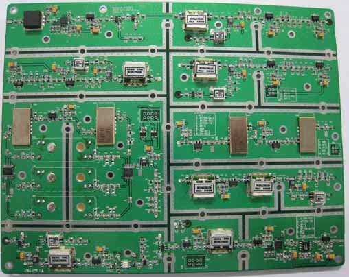
Click to zoom
Application Details
- Equipment Class
- PCB - PCS Licensed Transmitter
- Date of Grant
- Nov 24, 2007
- Application Purpose
- Original Equipment
- Date of Application
- Nov 21, 2007
- Equipment Note
- CDMA Mini RF Repeater
- Frequency Range
- 1930.00000000 - 1995.00000000
- Company
- R-tron Inc.
- Country
- South Korea
Documents & Files
Document Text
Text extracted from the exhibit documents filed with the FCC. Open a document above to read the original.
Users Manual
CDMA MINI User’s Manual -1- CDMA MINI (RSN-CDMA-30-C) User’s Manual R-tron Inc. CDMA MINI User’s Manual -2- CAUTION This equipment is indoor use and all the communication CDMA MINI User’s Manual -3- This document describes the specifications, installation and operation of CDMA MINI. Hardware and software mentioned in this document are subject to continuous development and improvement. Consequently, there may be minor discrepancies between the information in the document and the performance and design of the product. Specifications, dimensions and other statements mentioned in this document are subject to change without notice. R-tron Inc. 6402 College Boulevard Overland Park, KS 66211 Phone: +1-913-344-9977, 1-888-31R-TRON Fax: +1-913-344-9988 Internet: www.r- tron.com R-tron is registered trademarks of R-tron Inc. Other products and company names mentioned herein this manual might be trade marks or trade names of their respective owners. This document or parts of it may not be reproduced without the written permission of R-tron Inc. Infringements will be prosecuted. All rights reserved Copyright © R-tron Inc. 2000-2007 CDMA MINI User’s Manual -4- Contents Abbreviations ................................................................................................... 5 1. Introduction .................................................................................................. 6 2. Description .................................................................................................... 8 2.1 System Specifications ........................................................................................ 8 2.1.1 Electrical Specifications ......................................................................................... 8 2.1.2 Mechanical Specifications ...................................................................................... 9 2.2 Sub Unit Overview ........................................................................................... 10 2.2.1 Block diagram ...................................................................................................... 11 2.2.2 UDC Module ........................................................................................................ 12 2.2.3 Duplexer ............................................................................................................... 13 2.2.4 Main Control Unit (MCU) ..................................................................................... 14 2.2.5 Power Supply ....................................................................................................... 15 2.2.6 High Power Amplifier (HPA) ................................................................................. 16 3. Hardware Installation ................................................................................. 17 3.1 Check List of items ........................................................................................... 17 3.2 Mounting .......................................................................................................... 18 3.3 Grounding ........................................................................................................ 21 3.4 RF Cable Connection ....................................................................................... 22 3.5 Power Up ......................................................................................................... 22 4. Command and Control through the Hyper Terminal ............................... 23 4.1 Setting for Command and Control through the Web GUI....................................... 23 5. Command and Control on the Web GUI............................................26 5.1 DL and UL Bandwidth Selection........................................................................27 5.2 DL and UL DL and UL gain setting ..........................................................28 5.3 HPA On and OFF ............................................................................29 6. Troubleshooting ......................................................................................... 30 6.1 RF Connection check ....................................................................................... 30 6.2 Power Connection ............................................................................................ 30 6.3 Red Light on the Alarm LED ............................................................................. 30 CDMA MINI User’s Manual -5- Abbreviations Abbreviations used in this manual, in iDEN Add-On Filter Box. AC Alternating Current ANT Antenna CDMA Code Division Multiple Access DC Direct Current GND Grounding GUI Graphic User Interface LED Light Emitting Diode PSU Power Supply Unit MCU Main Control Unit UDC Up Down Converter RF Radio Frequency TEMP Temperature VSWR Voltage Standing Wave Ratio CDMA MINI User’s Manual -6- 1. Introduction CDMA MINI repeater is used to fill out areas in CDMA mobile systems, such as base station fringe areas, business and industrial buildings, etc. CDMA MINI receives signals from a base station, amplifies and retransmits the signals to mobile stations. Also it receives, amplifies and retransmits signals in the opposite direction. Both directions are served simultaneously with the following features: 65MHz bandwidth service Band Selection (5MHz , 10MHz , 15MHz , 20MHz , 5MHz+5MHz , 10MHz+5MHz, 15MHz+5MHz , 20MHz+5MHz , 5MHz+5MHz+5MHz) service Roll Offs: 65 dBc at 1 MHz outside pass-band The RSN-CDMA-30-C Repeaters are controlled by powerful microprocessors. Operational status LEDs are visible on the bottom of the repeater. The repeater works with convection cooling without fan because it has a radiator behind the Ground contact Donor antenna port AC in and Switch Alarm LEDs Local port Remote port DL and UL output monitoring DC Outlet for external device CDMA MINI User’s Manual -7- body of RSN-CDMA-30-C. Operational parameters, such as gain, power levels, ala…
Text truncated - open the document above for the full version.
Cover Letter(s)
Jisan IT Venture Center 2,3F, 1004-9,10, Doksan-Dong, Gumcheon-Gu, Seoul, Korea Tel: +82-2-896-4101 Fax: +82-2-896-4107 [email protected] September 28, 2007 Federal Communication Commission Equipment Authorization Branch 7435 Oakland Mills Road Columbia, MID 21046 In re: R-tron, Inc. FCC ID: STESNCDMA30C Wireless Repeater (CDMA) Part 24 Certification Request for Confidentiality Gentlemen: In accordance with 0.459 of CFR 47, R-tron Inc. hereby requests confidentiality of the Block Diagram, Circuit Diagrams, Repeater Description, Technical Specification, Parts List, and Tune-Up Procedure for the above-referenced certification application. These documents contain detailed system and equipment description and related information about the product which R-tron Inc. Considers to be proprietary, confidential, and a custom design and, otherwise, would not release to the general public. Since this design is a basis from which future technological products will evolve, R-tron Inc. considers this information to be of benefit to its competitors, such that the disclosure of the information in these documents would give competitors an unfair advantage in the market. Sincerely, R-tron, Inc.
Cover Letter(s)
Jisan IT Venture Center 2,3F, 1004-9,10, Doksan-Dong, Gumcheon-Gu, Seoul, Korea Tel: +82-2-896-4101 Fax: +82-2-896-4107 [email protected] September 28, 2007 Federal Communication Commission Equipment Authorization Branch 7435 Oakland Mills Road Columbia, MID 21046 In re: R-tron, Inc. FCC ID: STESNCDMA30C Wireless Repeater Part 24 Certification Request for Confidentiality To whom it may concern: We the undersigned R-tron,Inc. here by authorize ESTECH Co.,Ltd.(EST) of Korea to act on our behalf in all matters relating to all processes required in the FCC Part 24 approval and any communication needed with the national authority. Any and all acts carried out by EST on our behalf shall have the same effects as acts of our own. If you have any questions regarding the authorization, please don’t hesitate to contact us. Sincerely, yours Sincerely, Jong Hwa, Park/R&D Center Director R&D Center R-tron, Inc.
External Photos
RSN-CDMA-30-C EUT-Photograph *Repeater* <Front View > < Rear View > <Top view> <Bottom view> <Right side view> <Left side view>
Internal Photos
< The Inside of the Repeater > *RF-Module* <CDMA 30 DL Top View> <CDMA 30 DL PCB Top View> <CDMA 30 DL Bottom View> <CDMA 30 DL PCB Bottom View> <CDMA 30 UL Top view> <CDMA 30 UL PCB Top view> < CDMA 30 UL Bottom View> < CDMA 30 UL PCB Bottom View> *HPAs < CDMA 30 DL> < CDMA 30 DL> < CDMA 30 UL> < CDMA 30 UL> *MCU Board* <Top View> <Bottom View> *Power Supply Unit* *Duplexer* *Communication & LED Board* <Front side> <Rear side>
Test Report
Product Name Model Name RSN-CDMA-30-C ͑͑ESTECH CO., LTD. http://www.estech.co.kr FCC TEST REPORT Wireless Repeater(CDMA) Report Number : ESTR0711-0081 of 27 Applicant FCC ID STESNCDMA30C ESTECH CO., LTD Rm. 1015 World Venture Center, 426-5 Gasan-dong, Geumcheon-gu, Seoul, 153-803, Korea. Tel:82-2-867-3201, Fax:82-2-867-3204 R-TRON, Inc. Report Number : ESTR0711-0081 of 27 FCC ID : STESNCDMA30C Company Name Address Product Name Model No.Manufacturer Serial No. Country of origin Issued DateTested Date ͑͑ESTECH CO., LTD. http://www.estech.co.kr FCC Test Report Applicant Product Report Number RSN-CDMA-30-C KOREA R-TRON, Inc. Test Result Pass 2007-11-13 2007-10-15 ~ 2007-11-13 Other ESTR0711-008 Jisan IT Venture Bldg., 2/3F, 1004-9/10, Doksan-Dong, Gumcheon- Gu, Seoul, Korea Wireless Repeater(CDMA) NONE R-TRON, Inc. Report Number : ESTR0711-0082 of 27 Rm. 1015 World Venture Center, 426-5 Gasan-dong, Geumcheon-gu, Seoul, 153-803, Korea. Tel:82-2-867-3201, Fax:82-2-867-3204 ESTECH CO., LTD o This is certified that the above mentioned products have been tested for the sample provided by client. o No part of this document may not be duplicated or reproduced by any means without the express written permission of Estech Co., Ltd. Standard FCC PART 24 Subpart E Tested by Approved by I.K. Hong/ Engineer (Signature) Jay Kim/ Engineering Manager (Signature) Report Number : ESTR0711-0082 of 27 FCC ID : STESNCDMA30C 1. General Information Page 4 2. Laboratory Information Page 5 3. Summary of Test Results Page 5 4. RF Output Power Page 6 5. Occupied Bandwidth Page 11 6. Spurious and Harmonic Emission at Antenna Terminal Page 14 7. Field Strength of Spurious Radiation Page 24 8. Frequency stability Page 27 Contents ͑͑ESTECH CO., LTD. http://www.estech.co.kr Report Number : ESTR0711-0083 of 27Report Number : ESTR0711-0083 of 27 FCC ID : STESNCDMA30C 1. General Information 1.1 EUT Description Channel Uplink :1851.25 ~ 1908.75MHz Uplink&Downlink(25/600/1175) CDMA Frequency Downlink :1931.25 ~ 1988.75MHz Input: 110VAC(85 ~ 145VAC), Output: DC 7V Power Rating ͑͑ ESTECH CO., LTD. http://www.estech.co.kr FCC ID STESNCDMA30C Modulation Type Product Name Model Name Wireless Repeater(CDMA) RSN-CDMA-30-C Report Number : ESTR0711-0084 of 27Report Number : ESTR0711-0084 of 27 FCC ID : STESNCDMA30C 2. Laboratory Information 3. Summary of Test Results Result ͑͑ ESTECH CO., LTD. http://www.estech.co.kr 58-1, Osan-Ri, GaNam-Myon, YeoJoo-Gun, KyungKi-Do, Korea 97-1, Hoiuk-Ri Majang-Myon, Icheon-city, KyungKi-Do, Korea 2.4 Major Accredited Mark Test Item Accredited by KOLAS(ISO/IEC 17025) Head Office EMC Lab(Ichon) EMC Lab(Yanggi) Standard 2.1 Laboratory Name 2.2 Location 2.3 Quality System Estech Co., Ltd. Rm. 1015, World Venture Center II, 426-5 Gasan-dong Geumcheon-gu, Seoul, 153-803. Korea. PASS PASS PASS PASS RF Output Power Occupied Bandwidth PASS Part 24 Field Strength of Spurious Radiation Frequency stability Spurious and Harmonic Emission at Antenna Terminal Report Number : ESTR0711-0085 of 27 FCC ID : STESNCDMA30C 4. RF Output Power 4.1 Test Procedure 4.2 Test Equipments The following test equipments are used during tests Manufacturer Agilent ͑͑ ESTECH CO., LTD. http://www.estech.co.kr Signal GeneratorE4432B Equipment Spectrum Analyzer Power output shall be measured at the RF outut terminals when the transmitter is adjusted in accordance with the tune-up procedure to give the values of current and voltage on circuit elements as specified. The electrical characteristics of the radio frequency load attached to the output terminals when this test is made shall be stated Model E4407B HP Report Number : ESTR0711-0086 of 27 4.3.1 Test Results (Uplink) Conducted power Low25 Mid.600 High1175 29.92 29.94 1851.2529.97 Freq (MHz)Power Output (dBm)Ch No. 1880.00 1908.75 Report Number : ESTR0711-0086 of 27 FCC ID : STESNCDMA30C 4.3.2 Test Results (Downlink) Low25 Mid600 High1175 ͑͑ ESTECH CO., LTD. http://www.estech.co.kr Ch No.Freq (MHz)Power Output (dBm) 1931.2529.72 1960.0029.99 1988.7529.86 Report Number : ESTR0711-0087 of 27Report Number : ESTR0711-0087 of 27 FCC ID : STESNCDMA30C 4.4 Test Plot Uplink RF Power Output (25) RF Power Output (600) ͑͑ESTECH CO., LTD. http://www.estech.co.kr Report Number : ESTR0711-0088 of 27 RF Power Output (1175) Report Number : ESTR0711-0088 of 27 FCC ID : STESNCDMA30C Downlink RF Power Output (25) RF Power Output (600) ͑͑ESTECH CO., LTD. http://www.estech.co.kr Report Number : ESTR0711-0089 of 27 RF Power Output (1175) Report Number : ESTR0711-0089 of 27 FCC ID : STESNCDMA30C Input Signal Output Power Uplink (600) ͑͑ESTECH CO., LTD. http://www.estech.co.kr Report Number : ESTR0711-00810 of 27 Downlink (600) Report Number : ESTR0711-00810 of 27 FCC ID : STESNCDMA30C 5. Occupied Bandwidth 5.1 Test Procedure 5.2 Test Equipments The following test equipments are used during tests 5.3 Test Results ͑͑ ESTECH CO., LTD. http://www.estech.co.kr Signal Generator EquipmentModel E4407B E4432B The transmitter output is connected to the spectrum analyzer. The RBW is set to 1% of the Emission bandwidth. The VBW is set to 3 times the RBW. The sweep time is coupled. Manufacturer Spectrum AnalyzerAgilent HP Report Number : ESTR0711-00811 of 27 (Uplink) (Downlink) 11751908.751.39 6001880.001.39 251851.251.37 26dB Bandwidth(MHz)ChannelFrequency(MHz) ChannelFrequency(MHz)26dB Bandwidth(MHz) 251931.251.37 6001960.001.37 11751988.751.38 Report Number : ESTR0711-00811 of 27 FCC ID : STESNCDMA30C 5.4 Test Plot Uplink 26dB Channel Bandwidith(25) 26dB Channel Bandwidith(600) ͑͑ESTECH CO., LTD. http://www.estech.co.kr Report Number : ESTR0711-00812 of 27 26dB Channel Bandwidith(1175) Report Number : ESTR0711-00812 of 27 FCC ID : STESNCDMA30C Downlink 26dB Channel Bandwidith(25) 26dB Channel Bandwidith(600) ͑͑ESTECH CO., LTD. http://www.estech.co.kr Report Number : ESTR0711-00813 of 27 26dB Channel Bandwidith(1175) Report Number : ESTR0711-00813 of 27 FCC ID : STESNCDMA30C 6. Spurious and Harmonic Emission at Antenna T…
Text truncated - open the document above for the full version.
Test Setup Photos
RSN-CDMA-30-C Tune-Up Procedure R-tron Inc. 1. Power On a. Connect the power cord. b. Plug the power cord into a wall outlet. c. Switch on. d. Check if the green LED at the bottom turns on. 2. DL Test Configurations 30 dB attenuator Plugged into AC outlet DL Gain Specification Parameter Down Link Gain 90dB Input Level Output Level -60dBm 30dBm 3. UL Test Configurations UL Gain Specification Parameter Down Link Gain 90dB Input Level Output Level -60dBm 30dBm 4. Setting for Command and Control through the Web GUI * CDMA MINI operates on a customer provided PC based platform with the following system requirements. Windows® XP Strong recommended 128 MB RAM or more Pentium processor or more keyboard RJ-45 jack Step 1 Open My Network Places. Step 2 Click the “View network connections”. Step 3 Push the right button of mouse and select the properties. Step 4 Click the properties of TCP/IP. Step 5 Set the values and OK as the following. Close all windows. Step 6 Open a new explorer window. Step 7 Type http://192.168.0.2:83 in the address box and press “Enter” key. Step 8 Login with “admin” of ID and “1234” of password and “OK”. 5. Command and Control on the Web GUI 5.1 DL and UL Bandwidth Selection a. To control the CDMA MINI, check the box of PCS 1900. b. The operating bandwidth,5MHz,10MHz,15MHz,20MHz,5+5MHz,10+5MHz,15+5MHz, 20+5MHz, 5+5+5MHz bandwidth is possibly selected. Select the operating bandwidth and push the “APPLY” and check the bandwidth. c. The operating frequency is able to be selected. Select the operating frequency and push the “APPLY” and check the bandwidth and frequency. 5.2 DL and UL DL and UL gain setting a. Set the DL gain and UL gain, 50dB to 90dB, and push the “APPLY” button. 5.2 HPA On and OFF a. Press the “ON” and “OFF” and check the status. The maximum output power for operating is +30dBm on both DL and UL.
Contact Information
Applicant
Yong Hoon Kang
Technical Contact
ESTechJay Kim
[email protected]+82 2 867 3201
Room 1015, World Venture Center II · Seoul · South Korea
Test Firm
Estech Co., Ltd.Ike Chung
Technical Specifications
| # | Rule Parts | Frequency Range | Power Output | Emission | Tolerance |
|---|---|---|---|---|---|
| 2 | 24E | 1.93 GHz - 2.00 GHz | 997.00 mW | F9W | Amp |
Other Applications from R-tron Inc.

STE-APEX8930
Dec 05, 2011RF Repeater
Equipment Class
TNB - Licensed Non-Broadcast Station Transmitter
STE-QUADCOMM-700N
Oct 19, 2011LTE Repeater
Equipment Class
TNB - Licensed Non-Broadcast Station Transmitter
STE-APEX730
Oct 14, 2011LTE Band Repeater
Equipment Class
TNB - Licensed Non-Broadcast Station Transmitter
STE-APEX1924
Apr 27, 2011Repeater
Equipment Class
PCB - PCS Licensed Transmitter
STE-APEX1930
Apr 25, 2011Repeater
Equipment Class
PCB - PCS Licensed Transmitter