STESNTRIDCWireless Booster(CDMA)
R-tron Inc.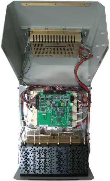
Click to zoom
Application Details
- Equipment Class
- PCB - PCS Licensed Transmitter
- Date of Grant
- Mar 26, 2008
- Application Purpose
- Original Equipment
- Date of Application
- Mar 25, 2008
- Equipment Note
- Wireless Booster(CDMA)
- Frequency Range
- 1930.00000000 - 1995.00000000
- Company
- R-tron Inc.
- Country
- South Korea
Documents & Files
Document Text
Text extracted from the exhibit documents filed with the FCC. Open a document above to read the original.
Users Manual
Notice Trademark R-tron is a registered trademark of R-tron Inc. Other products and company names mentioned here in this manual might be trademarks or trade names of their respective owners. Copyright Copyright © R-tron Inc. 2000-2008 All Rights Reserved Any reproduction, distribution, or revisions of any or all portions of this manual is prohibited without written permission from R-tron Inc. Notice This document describes the specifications, installation, and operation of the Tri MINI. Hardware and software mentioned in this document are subject to continuous development and improvement. Consequently, there may be minor discrepancies between the information in the document, performance, and design of the product. Specifications, dimensions, and other statements mentioned in this document are subject to change without notice. Questions or Comments Address: R-tron Inc. 6402 College Boulevard, Overland Park, KS 66211 Phone: +1-913-344-9977, 1-888-31R-TRON Fax: +1-913-344-9988 e-mail: [email protected] Website: www.r-tron.com 1 User’s Manual Safety Precautions Safety Precautions Warning Opening the Tri MINI could result in electric shock and may cause severe injury. Warning Connect the equipment frame ground to building ground. Warning Operating the Tri MINI with antennas in very close proximity facing each other could lead to severe damage to the repeater. Caution RF EXPOSURE INFORMATION A minimum separation distance of 7.9 inches (20cm) must be maintained between the user and the external antenna of repeater to satisfy FCC RF exposure requirements. For more information about RF exposure, please visit the FCC website at www.fcc.gov Caution This equipment is for indoor use and enables the communication wiring to communicate only inside the building. 2 Contents Glossary 1. Introduction 2. Description 2.1 Main Unit Overview 2.2 Sub Unit Overview 2.2.1 Block Diagrams 2.2.2 PSU (Power Supply Unit) 2.2.3 UDCs (Up Down Converter) 2.2.4 MCU (Main Control Unit) 2.2.5 HPAs (High Power Amplifiers) 2.2.6 Multiplexer 3. Hardware Installation 3.1 Check List of Items 3.1.1 Items 3.2 Mounting 3.3 Grounding 3.4 RF Cable Connection 3.5 Power On 4. Operation 4.1 Connections 4.2 System Requirements 4.3 Network Setup 4.3.1 Windows XP 4.3.2 Windows 2000 4.3.3 Windows Vista 4.4 System Login 4.5 System Setup 5. Troubleshooting 6. Specifications 7. Appendix 3 4 6 6 7 8 9 10 11 12 13 14 14 14 15 18 18 20 21 21 22 22 22 25 27 31 33 69 72 75 3 User’s Manual Glossary The following is a list of abbreviations and terms used in this manual. Glossary ALC (Automatic Level Control) ALC feature prevents the repeater from exceeding its maximum output power by reducing the gain automatically. ALC is used to adjust the gain to an appropriate level for a range of input signal levels. ASD (Automatic Shutdown) Automatic shut down protects the repeater from the oscillation or excessive input signal and eliminates any degradation to the network. There are three parameters: ASD LEVEL, ASD TIME and ASD COUNT. If the output power gets higher than “ASD LEVEL”, the repeater will shut down for “ASD TIME” seconds and then it will turn the amp back on to measure the output power again. If this repeats at “ASD COUNT” times, the repeater will shut down completely. Abbreviation AC ALC ANT ASD DC GND GUI iDEN LED PSU RF TEMP VSWR Definition Alternating Current Automatic Level Control Antenna Automatic Shutdown Direct Current Grounding Graphic User Interface Integrated Digital Enhanced Network Light Emitting Diode Power Supply Unit Radio Frequency Temperature Voltage Standing Wave Ratio 4 Tri MINI repeater is used to fill out areas in iDEN and CDMA mobile systems, such as base station fringe areas, business and industrial building, etc. Tri MINI receives signals from a base station, amplifies and retransmits the signals to mobile stations. Also it receives, amplifies and retransmits signals in the opposite direction. Both directions are served simultaneously with the following features: 1. Introduction a. iDEN • 7MHz or 18MHz-bandwidth service @ 800MHz’s • 5MHz-bandwidth service @ 900MHz’s • Adjustable Band Edge @ 800MHz’s and 900MHz’s • Roll Offs: 65dBc at 0.5MHz outside pass-band • Remote Access and Control • Easy and Quick Installation - Web-based GUI - Plug and Play – DHCP Server @ Local Port an DHCP Client @ Remote Port - Easy Setup(Automatic) - Isolation Detection • Auto Level Control & Auto Shut Down b. CDMA • Programmable Bandwidth and Band - 5, 10, 15, and 20MHz contiguous and non-contiguous segments - Any Band Combination within 65MHz PCS Band [A, D, B, E, F, C, G] - Three(3) 5MHz segments • Remote Access and Control • Easy and Quick Installation - Web-based GUI - Plug and Play – DHCP Server @ Local Port an DHCP Client @ Remote Port - Easy Setup(Automatic) - Isolation Detection • Auto Level Control & Auto Shut Down 5 User’s Manual 1. Introduction - TRI MINI utilizes the web-based user interface and web server to support the remote access and control through an external monitoring device with wireless modem. There are two physical RJ-45 ports: • The Local port provides the on-site access to the repeater. • The remote port allows remote users to access the repeater through an external monitoring device. The two ports allow local remote users to access the repeater simultaneously. - DHCP server at the Local port enables Plug and Play by automatically assigning the IP address to the user’s computer. - Parameter setup is only one click away • Easy setup feature will measure the isolation and limit the maximum gain accordingly. This will also enable Auto Level Control as well as Auto Shut Down. These two features are strongly recommended to prevent the uncontrolled power output, which could have an adverse impact on the RF network and the repeater. For example, ALC will automatically apply attenuation when the input signal strength is increased due to the new base station deployment near the repeater site. TriMINI Pluggedinan ACoutlet Base Sta…
Text truncated - open the document above for the full version.
Users Manual
24 4. Operation Select Internet Protocol (TCP/IP) and click Properties. Step 4 Check Obtain an IP address automatically and click OK. Step 5 Close all windows. Step 6 25 User’s Manual 4. Operation 4.3.2 Windows 2000 Click the Start button, point to Settings, and then click Network and Dial-up Connections. Step 1 Right-click Local Area Connection to see a shortcut menu and click Properties. Step 2 26 4. Operation Select Internet Protocol (TCP/IP) and click Properties. Step 3 Check Obtain an IP address automatically and click OK. Step 4 Close all windows. Step 5 27 User’s Manual 4. Operation 4.3.3 Windows Vista Click the Start button and Control Panel. Step 1 Click Network and Internet. Step 2 28 4. Operation Click Network and Sharing Center. Step 3 Click View status of Local Area Connection. Step 4 29 User’s Manual 4. Operation Click Properties and a caution pop-up window will appear. Click OK. Step 5 Select Internet Protocol Version 4 (TCP/IPv4) and click Properties. Step 6 30 4. Operation Check Obtain an IP address automatically and click OK. Step 7 Close all windows. Step 8 31 User’s Manual 4. Operation 4.4 System Login Open your Web browser and type “192.168.0.1:83” into the URL address box. Then press the Enter key. Step 1 The logon screen will appear. Type “operator” for the ID and “rtron” for the password and then click OK. Step 2 32 4. Operation The pop-up message for the login success will appear. Click OK. Step 3 The login process is complete. The Initial screen will appear. Step 4 In case of the initial login, you should input Cascade Code and Location Information of Network Setup. Otherwise a warning pop-up window will appear and you cannot access any of the menus. Step 5 33 User’s Manual 4. Operation Operator has no authorization to access this menu. Click Clock in the left menu. In this menu, you can set the date and the time. Click Set Date/Time. 4.5 System Setup 4.5.1 Security 4.5.2 Clock 34 4. Operation Click Network in the left menu. 4.5.3 Network Network Setup • Cascade Code: Type in the pre-assigned code. Otherwise, you cannot access system setup. • Location Information: Enter the latitude and longitude of a location, otherwise you cannot access the system setup. You can input either Decimal Degrees or Degrees-Minutes-Seconds. [Example.] (‘N/S ‘ | ‘E/W ‘) ddd.dddddd: (Latitude: N 39.006957 Longitude: W 94.532306) • Heartbeat Interval: Sets the time to transmit the Heartbeat to NMC Server. (Default value is 20 minutes. At the setup, temporarily reduce the value to 1 minute. After conforming heartbeat report, set the value back to 20 minutes.) • Product Information: This is for manufacturer used only. DO NOT change this value. • Static IP for Remote Control: Connect to the External Monitoring Device for Remote Access. Do not enter any value unless a static IP is assigned. DHCP client. • NMC Server IP: Do not change this value; otherwise, the Heartbeat transmission or Remote Access may not work. 35 User’s Manual 4. Operation User Note • Location Information: Type the location information such as the building name, address, city, state, zip code and telephone, and then click SAVE to save the information you provide. • Donor Site Information: Type the base station’s ID, and then click SAVE to save the information you provide. • Installer Information: Type the installer information such as the company, name and telephone, and then click SAVE to save the information you provide. • User Comment: You can add comments. Up to 50 comments can be stored in the memory. The length of characters for each comment is limited to 60 characters. 36 4. Operation Check IDEN in the left menu. 4.5.4 Control a. iDEN 37 User’s Manual 4. Operation Parameter Setup • Bandwidth/Frequency: - For IDEN 800 If you select 18 MHz for bandwidth, the values of the frequency range are 851~869, 851~868.8, 851~868.6. If you select 7 MHz for bandwidth, the values of the frequency range is 862~869, 862~868.8, 862~868.6. - For IDEN 900 The values of the frequency range is 935~940, 935~939.8, 935~939.6. 38 4. Operation Solution 1. Easy Setup [Recommended] Return to Factory Defaults Step 1 • To reset factory defaults, click INITIALIZE. • To restore the previous settings, click RESTORE. Step 2 Select the operating bandwidth and operating frequencies (5MHz-bandwidth fixed in iDEN 900) and click APPLY. Easy Setup Step 3 Easy Setup proceeds to: • Isolation measurement On • Calculation of Available Maximum Gain by the isolation. • ASD On • ALC On to get Maximum DL Output Power 25dBm [Defaults] or Maximum Gain 80dB. Click Execute. 39 User’s Manual 4. Operation Easy setup feature will measure the isolation and limit the maximum gain accordingly. This will also enable Auto Level Control as well as Auto Shut Down. These two features are strongly recommended to prevent the uncontrolled power output, which could have an adverse impact on the RF network and the repeater. For example, ALC will apply attenuation automatically when the input signal strength is increased due to the new base station deployment near the repeater site. Click OK. Step 4 Click OK again. Step 5 41 User’s Manual 40 4. Operation 4. Operation Setup will automatically begin. This process will take approximately 20seconds. Step 6 10~20 seconds Click IDEN in the left menu. 41 User’s Manual 40 4. Operation 4. Operation Constant Maximum DL Output Power 25dBm if the DL Input Power ≥-55dBm. Result 1 42 4. Operation Maximum Gain 80dB if the DL Input Power <-55dBm. Result 2 After running Easy Setup or Isolation Measurement, Isolation is displayed with “95” when the isolation is higher than 95dB, or it is displayed with the actual when the isolation is lower than 95dB. •Automatic Level Control: Type under 25 and then click APPLY and ON. [Example] For the repeater with 25dBm maximum output power, 80dB maximum gain / 30dB gain control range, → If the signal -45dBm and the ALC is set as 25dBm the gain will be 70dB to adjust to the output power. If the input signal is -…
Text truncated - open the document above for the full version.
Users Manual
48 4. Operation 49 User’s Manual 4. Operation Alarms • Reported to Sprint : If an alarm occurs, the repeater will report directly to Sprint as a SNMP Trap so the LED of ALARM on the repeater does not blink. • On Site Alarm : If an alarm occurs, the alarm LED on the repeater will turn on. Please refer to the troubleshooting section of this manual. • No change of the values in the alarm range is recommended. < Alarm Status >< Alarm Range > 50 4. Operation Check CDMA in the left menu. Setup b. CDMA 51 User’s Manual 4. Operation Solution 1. Easy Setup [Recommended] Return To Factory Defaults Step 1 Select Bandwidth and Band and click APPLY. Step 2 • To reset to factory defaults, click INITIALIZE. • To restore the previous settings, click RESTORE. Easy Setup Step 3 Easy Setup proceeds to: • Isolation measurement On • Calculation of Available Maximum Gain by the isolation. • ASD On • ALC On to get Maximum DL Output Power 24dBm [Default] or Maximum Gain 80dB. 53 User’s Manual 52 4. Operation 4. Operation Click Execute. Easy setup feature will measure the isolation and limit the maximum gain accordingly. This will also enable Auto Level Control as well as Auto Shut Down. These two features are strongly recommended to prevent the uncontrolled power output, which could have an adverse impact on the RF network and the repeater. For example, ALC will apply attenuation automatically when the input signal strength is increased due to the new base station deployment near the repeater site. Click OK. Step 4 Click OK again. Step 5 53 User’s Manual 52 4. Operation 4. Operation Setup will automatically begin. This process will take approximately 20 seconds. Step 6 10~20 seconds Click CDMA in the left menu. 55 User’s Manual 54 4. Operation 4. Operation Constant Maximum DL Output Power 24dBm if the DL Input Power >= -56dBm Result 1 55 User’s Manual 54 4. Operation 4. Operation Maximum Gain 80dB if the DL Input Power < -56dBm. Result 2 57 User’s Manual 56 4. Operation 4. Operation Solution 2. DL Output Power < Max. 24dBm Repeat step 1 through step 6. Step 2A Step 1A Change the level at Automatic Level Control and click APPLY. After running Easy Setup or Isolation Measurement, Isolation value is displayed with “95” when the isolation is higher than 95dB, or it is displayed with the actual value when the isolation is lower than 95dB. • Automatic Level Control: Type under 24 and then click APPLY and ON. [Example] For the repeater with 24dBm maximum output power, 80dB maximum gain/ 40dB gain control range, → If the signal -36dBm and the ALC is set as 24dBm, the gain will be 60dB to adjust to the output power. If the input signal is -61dBm, the output power will be 19dBm by the limitation of the maximum gain even though the ALC is set as 24dBm. • Automatic Shutdown: Type the desired values for dBm, seconds, and times and then click APPLY and ON. (e.g. 27 dBm, 10 seconds, 3 times) [Example] For the repeater with 24dBm maximum output power, 80dB maximum gain/40dB gain control range, Assuming ASD Level: 27dBm, ASD Time: 10seconds, ASD Count: 3. If the output power is 27dBm (ASD LEVEL) and higher, the repeater will shutdown for 10 seconds (ASD TIME). If shutdown occurs 3 times (ASD COUNT), the 4th shutdown will be permanent. 57 User’s Manual 56 4. Operation 4. Operation Constant output power set as the ALC level. Result 59 User’s Manual 58 4. Operation 4. Operation Solution 3. Fixed Gain [Not Recommended] Easy Setup will calculate the Available Maximum Gain which defines the maximum gain to be setup. Repeat step 1 through step 6. Step 1B DO NOT setup the gain higher than the Available Maximum Gain. Warning Read DL Input Power and the gain controlled by Easy Setup. Step 2B 59 User’s Manual 58 4. Operation 4. Operation Turn off DL Amplifier and UL Amplifier. Step 3B ALC must be turned off; otherwise, the following message appears. Step 4B Change DL Gain and UL Gain. The gain must be lower than the current value and Available Maximum Gain. Warning Step 5B Turn on DL Amplifier and UL Amplifier. Step 6B 61 User’s Manual 60 4. Operation 4. Operation DL and UL gain are fixed and the output power depends on the input power. Result ► Tip Applying Uplink Gain Offset Downlink Gain Uplink Gain Uplink Gain Offset 61 User’s Manual 60 4. Operation 4. Operation Uplink Gain Offset = -3dB Result Alarms < Alarm Status >< Alarm Range > ※ Restore Restore recovers the service by turning on the amplifiers of repeater fundamentally. After a permanent shutdown, the Restore turns on the amplifiers of the repeater with the period of Restore Interval. 62 • Reported to Sprint : If an alarm occurs, the repeater will report directly to Sprint as a SNMP Trap so the LED of ALARM on the repeater does not blink. • On Site Alarm : If an alarm occurs, the alarm LED on the repeater will turn on. Please refer to the troubleshooting section of this manual. • No change of the values in the alarm range is recommended. 4. Operation 63 User’s Manual 4. Operation A pop-up window will appear. Select the firmware file and click Open. Step 2 Click Upload in the left menu. 4.5.5.1 Update: System Firmware 4.5.5 Upload Click Browse. Step 1 64 4. Operation Click UPDATE. Step 3 A pop-up window will appear after completing all the update processes. Click OK to reboot the system. Step 4 It will take a few minutes to update the new firmware. If the system reboots, go to the login page and login again. * Login page: http://192.168.0.1:83 (Local access) A specified IP address on DHCP(Remote access). Step 5 65 User’s Manual 4. Operation 4.5.5.2 Update: Web GUI Click Browse. Step 1 A pop-up window will appear. Select the GUI file and click Open. Step 2 Click UPDATE. Step 3 66 4. Operation A pop-up window will appear after completing all the update processes. Click OK to reboot the system. Step 4 4.5.5.3 Restore To restore the previous version, click RESTORE. It will take a few minutes to update the new Web GUI. If the system reboots, go to the login page and login again. * Log…
Text truncated - open the document above for the full version.
Cover Letter(s)
Jisan IT Venture Center 2,3F, 1004-9,10, Doksan-Dong, Gumcheon-Gu, Seoul, Korea Tel: +82-2-896-4101 Fax: +82-2-896-4107 [email protected] March 01. 2008 Federal Communication Commission Equipment Authorization Branch 7435 Oakland Mills Road Columbia, MID 21046 In re: R-tron, Inc. FCC ID:STESNTRIDC Wireless Booster Part 90 & Part 24 Certification Request for Confidentiality To whom it may concern: We the undersigned R-tron,Inc. here by authorize ESTECH Co.,Ltd.(EST) of Korea to act on our behalf in all matters relating to all processes required in the FCC Part 90 & Part 24 approval and any communication needed with the national authority. Any and all acts carried out by EST on our behalf shall have the same effects as acts of our own. If you have any questions regarding the authorization, please don’t hesitate to contact us. Sincerely, yours Sincerely, Jong Hwa, Park/R&D Center Director R&D Center R-tron, Inc.
Cover Letter(s)
Jisan IT Venture Center 2,3F, 1004-9,10, Doksan-Dong, Gumcheon-Gu, Seoul, Korea Tel: +82-2-896-4101 Fax: +82-2-896-4107 [email protected] March 01, 2008 Federal Communication Commission Equipment Authorization Branch 7435 Oakland Mills Road Columbia, MID 21046 In re: R-tron, Inc. FCC ID:STESNTRIDC Wireless Booster Part 90 & Part 24 Certification Request for Confidentiality Gentlemen: The service provider, Sprint with Nextel, requests to cover with 65MHz-bandwidth; from 1850MHz to 1915MHz of uplink and from 1930MHz to 1995MHz of downlink frequency. For the reasons, G-block is included as an operating frequency range of RSN-TRI-25/24-DC. Sprint with Nextel is planning to serve on G- block in the nearest future. Hence, R-tron supports the frequency plan of Sprint with Nextel. Sincerely, R-tron, Inc.
Cover Letter(s)
Jisan IT Venture Center 2,3F, 1004-9,10, Doksan-Dong, Gumcheon-Gu, Seoul, Korea Tel: +82-2-896-4101 Fax: +82-2-896-4107 [email protected] March 01. 2008 Federal Communication Commission Equipment Authorization Branch 7435 Oakland Mills Road Columbia, MID 21046 In re: R-tron, Inc. FCC ID: STESNTRIDC Wireless Booster Part 90 Certification Request for Confidentiality Gentlemen: In accordance with 0.459 of CFR 47, R-tron Inc. hereby requests confidentiality of the Block Diagram, Circuit Diagrams, Repeater Description, Technical Specification, Parts List for the above- referenced certification application. These documents contain detailed system and equipment description and related information about the product which R-tron Inc. Considers to be proprietary, confidential, and a custom design and, otherwise, would not release to the general public. Since this design is a basis from which future technological products will evolve, R-tron Inc. considers this information to be of benefit to its competitors, such that the disclosure of the information in these documents would give competitors an unfair advantage in the market. Sincerely, Jong Hwa, Park/R&D Center Director R&D Center R-tron, Inc.
External Photos
RSN-TRI-25/24-DC EUT-Photograph *Repeater* <Front View > < Rear View > <Top view> <Bottom view> <Left side view> <Right side view> < The Inside of the Repeater >
ID Label/Location Info
ma y n ot h armf ul in terference. RSN-iDEN-30 COMPLIES W ITH PART 90, FCC RULES. 110 -125V ~ , 60Hz , 4A :PRODUCT PART NUMBER POWER : FCC REG. NO. : STESNiDEN30 SERIAL NO. / DATE : E25 810 9 31CY I.T.E :MAKER MADE IN KOREA R-tron lnc. Operation is su bject to th e cond ition that this device Th is d ev ice co mpl ies with Part 1 5 of the FCC Rules. BRACKET LAN ALARM AC IN 110 -125V ~ 800MHz TX MON. 900MHz RX MON. DONOR ANTENNA SERVICE ANTENNA 900MHz TX MON. 800MHz RX MON.
Internal Photos
*UDC * a. iDEN <RSN-TRI-25/24-DC UDC Top view> <RSN-TRI-25/24-DC 800 UDC> <RSN-TRI-25/24-DC 900 UDC> <RSN-iDEN-DSP BOARD> b. CDMA <RSN-TRI-25/24-DC DL Top View> <RSN-TRI-25/24-DC DL PCB Top View> <RSN-TRI-25/24-DC DL Bottom View> <RSN-TRI-25/24-DC DL PCB Bottom View> <RSN-TRI-25/24-DC UL Top view> <RSN-TRI-25/24-DC UL PCB Top view> < RSN-TRI-25/24-DC UL Bottom View> < RSN-TRI-25/24-DC UL PCB Bottom View> *HPA* a. iDEN <RSN-TRI-25/24-DC HPA Top View> <RSN-TRI-25/24-DC HPA> b. CDMA <RSN-TRI-25/24-DC UL HPA Top View> <RSN-TRI-25/24-DC UL HPA> <RSN-TRI-25/24-DC DL HPA Top View> <RSN-TRI-25/24-DC DL HPA> *MCU Board* *Communication & LED Board* <Front side> <Rear side>
Test Report
Product Name Model Name RSN-TRI-25/24-DC ͑͑ESTECH CO., LTD. http://www.estech.co.kr FCC TEST REPORT Wireless Booster(CDMA) Report Number : ESTR0803-0061 of 27 Applicant FCC ID STESNTRIDC ESTECH CO., LTD Rm. 1015 World Venture Center, 426-5 Gasan-dong, Geumcheon-gu, Seoul, 153-803, Korea. Tel:82-2-867-3201, Fax:82-2-867-3204 R-TRON, Inc. Report Number : ESTR0803-0061 of 27 FCC ID : STESNTRIDC Company Name Address Product Name Model No.Manufacturer Serial No. Country of origin Issued DateTested Date ͑͑ESTECH CO., LTD. http://www.estech.co.kr FCC Test Report Applicant Product Report Number RSN-TRI-25/24-DC KOREA R-TRON, Inc. Test Result Pass 2008-03-12 2008-02-01 ~ 2008-03-12 Other ESTR0803-006 Jisan IT Venture Bldg., 2/3F, 1004-9/10, Doksan-Dong, Gumcheon- Gu, Seoul, Korea Wireless Booster(CDMA) NONE R-TRON, Inc. Report Number : ESTR0803-0062 of 27 Rm. 1015 World Venture Center, 426-5 Gasan-dong, Geumcheon-gu, Seoul, 153-803, Korea. Tel:82-2-867-3201, Fax:82-2-867-3204 ESTECH CO., LTD o This is certified that the above mentioned products have been tested for the sample provided by client. o No part of this document may not be duplicated or reproduced by any means without the express written permission of Estech Co., Ltd. Standard FCC PART 24 Subpart E Tested by Approved by I.K. Hong/ Engineer (Signature) Eun-young Son/ Engineering Manager (Signature) Report Number : ESTR0803-0062 of 27 FCC ID : STESNTRIDC 1. General Information Page 4 2. Laboratory Information Page 5 3. Summary of Test Results Page 5 4. RF Output Power Page 6 5. Occupied Bandwidth Page 11 6. Spurious and Harmonic Emission at Antenna Terminal Page 14 7. Field Strength of Spurious Radiation Page 24 8. Frequency stability Page 27 Contents ͑͑ESTECH CO., LTD. http://www.estech.co.kr Report Number : ESTR0803-0063 of 27Report Number : ESTR0803-0063 of 27 FCC ID : STESNTRIDC 1. General Information 1.1 EUT Description Channel Uplink :1851.25 ~ 1908.75MHz Uplink&Downlink(25/600/1175) CDMA Frequency Downlink :1931.25 ~ 1988.75MHz Input: 110VAC(85 ~ 145VAC), Output: DC 7V Power Rating ͑͑ ESTECH CO., LTD. http://www.estech.co.kr FCC ID STESNTRIDC Modulation Type Product Name Model Name Wireless Booster(CDMA) RSN-TRI-25/24-DC Report Number : ESTR0803-0064 of 27Report Number : ESTR0803-0064 of 27 FCC ID : STESNTRIDC 2. Laboratory Information 3. Summary of Test Results Result ͑͑ ESTECH CO., LTD. http://www.estech.co.kr 58-1, Osan-Ri, GaNam-Myon, YeoJoo-Gun, KyungKi-Do, Korea 97-1, Hoiuk-Ri Majang-Myon, Icheon-city, KyungKi-Do, Korea 2.4 Major Accredited Mark Test Item Accredited by KOLAS(ISO/IEC 17025) Head Office EMC Lab(Ichon) EMC Lab(Yanggi) Standard 2.1 Laboratory Name 2.2 Location 2.3 Quality System Estech Co., Ltd. Rm. 1015, World Venture Center II, 426-5 Gasan-dong Geumcheon-gu, Seoul, 153-803. Korea. PASS PASS PASS PASS RF Output Power Occupied Bandwidth PASS Part 24 Field Strength of Spurious Radiation Frequency stability Spurious and Harmonic Emission at Antenna Terminal Report Number : ESTR0803-0065 of 27 FCC ID : STESNTRIDC 4. RF Output Power 4.1 Test Procedure 4.2 Test Equipments The following test equipments are used during tests Manufacturer Agilent ͑͑ ESTECH CO., LTD. http://www.estech.co.kr Signal GeneratorE4432B Equipment Spectrum Analyzer Power output shall be measured at the RF outut terminals when the transmitter is adjusted in accordance with the tune-up procedure to give the values of current and voltage on circuit elements as specified. The electrical characteristics of the radio frequency load attached to the output terminals when this test is made shall be stated Basic Standard 47 CFR § 2.1046 Model E4407B HP Report Number : ESTR0803-0066 of 27 4.3.1 Test Results (Uplink) Conducted power Low25 Mid.600 High1175 25.09 25.13 1851.2525.05 Freq (MHz)Power Output (dBm)Ch No. 1880.00 1908.75 Report Number : ESTR0803-0066 of 27 FCC ID : STESNTRIDC 4.3.2 Test Results (Downlink) Low25 Mid600 High1175 ͑͑ ESTECH CO., LTD. http://www.estech.co.kr Ch No.Freq (MHz)Power Output (dBm) 1931.2522.32 1960.0022.45 1988.7522.67 Report Number : ESTR0803-0067 of 27Report Number : ESTR0803-0067 of 27 FCC ID : STESNTRIDC 4.4 Test Plot Uplink RF Power Output (25) RF Power Output (600) ͑͑ESTECH CO., LTD. http://www.estech.co.kr Report Number : ESTR0803-0068 of 27 RF Power Output (1175) Report Number : ESTR0803-0068 of 27 FCC ID : STESNTRIDC Downlink RF Power Output (25) RF Power Output (600) ͑͑ESTECH CO., LTD. http://www.estech.co.kr Report Number : ESTR0803-0069 of 27 RF Power Output (1175) Report Number : ESTR0803-0069 of 27 FCC ID : STESNTRIDC Input Signal Output Power Uplink (600) ͑͑ESTECH CO., LTD. http://www.estech.co.kr Report Number : ESTR0803-00610 of 27 Downlink (600) Report Number : ESTR0803-00610 of 27 FCC ID : STESNTRIDC 5. Occupied Bandwidth 5.1 Test Procedure 5.2 Test Equipments The following test equipments are used during tests 5.3 Test Results (Uplink) ͑͑ESTECH CO., LTD. http://www.estech.co.kr Signal Generator EquipmentModel E4407B E4432B The transmitter output is connected to the spectrum analyzer. The RBW is set to 1% of the Emission bandwidth. The VBW is set to 3 times the RBW. The sweep time is coupled. Basic Standard 47 CFR § 2.1049 Manufacturer Spectrum AnalyzerAgilent HP Report Number : ESTR0803-00611 of 27 (Uplink) (Downlink) 11751908.751.38 6001880.001.37 251851.251.37 26dB Bandwidth(MHz)ChannelFrequency(MHz) ChannelFrequency(MHz)26dB Bandwidth(MHz) 251931.251.38 6001960.001.37 11751988.751.37 Report Number : ESTR0803-00611 of 27 FCC ID : STESNTRIDC 5.4 Test Plot Uplink 26dB Channel Bandwidith(25) 26dB Channel Bandwidith(600) ͑͑ESTECH CO., LTD. http://www.estech.co.kr Report Number : ESTR0803-00612 of 27 26dB Channel Bandwidith(1175) Report Number : ESTR0803-00612 of 27 FCC ID : STESNTRIDC Downlink 26dB Channel Bandwidith(25) 26dB Channel Bandwidith(600) ͑͑ESTECH CO., LTD. http://www.estech.co.kr Report Number : ESTR0803-00613 of 27 26dB Channel Bandwidith(1175) Report Number : ESTR0803-00613 of 27 FCC ID : STESN…
Text truncated - open the document above for the full version.
Contact Information
Applicant
Yong Hoon Kang
Technical Contact
ES TechIn Ki Hong
[email protected]82-2-867-3201
Rm 1025 World Venture Center 426-5 Gasan-dong · Seoul · South Korea
Test Firm
ESTECH Co., Ltd.Yang Jinmo
Technical Specifications
| # | Rule Parts | Frequency Range | Power Output | Emission | Tolerance |
|---|---|---|---|---|---|
| 2 | 24E | 1.93 GHz - 2.00 GHz | 185.00 mW | F9W | Amp |
Other Applications from R-tron Inc.

STE-APEX8930
Dec 05, 2011RF Repeater
Equipment Class
TNB - Licensed Non-Broadcast Station Transmitter
STE-QUADCOMM-700N
Oct 19, 2011LTE Repeater
Equipment Class
TNB - Licensed Non-Broadcast Station Transmitter
STE-APEX730
Oct 14, 2011LTE Band Repeater
Equipment Class
TNB - Licensed Non-Broadcast Station Transmitter
STE-APEX1924
Apr 27, 2011Repeater
Equipment Class
PCB - PCS Licensed Transmitter
STE-APEX1930
Apr 25, 2011Repeater
Equipment Class
PCB - PCS Licensed Transmitter