STESPAPE030MPCS Band In-Building CDMA Booster
R-tron Inc.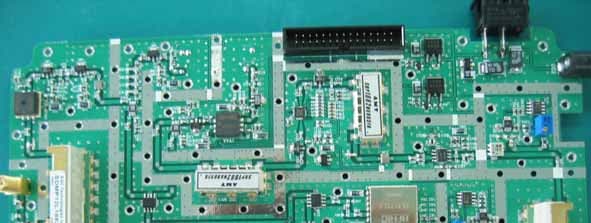
Click to zoom
Application Details
- Equipment Class
- PCB - PCS Licensed Transmitter
- Date of Grant
- May 31, 2006
- Application Purpose
- Original Equipment
- Date of Application
- May 25, 2006
- Equipment Note
- PCS Band In-Building CDMA Booster
- Frequency Range
- 1930.00000000 - 1995.00000000
- Company
- R-tron Inc.
- Country
- South Korea
Documents & Files
Document Text
Text extracted from the exhibit documents filed with the FCC. Open a document above to read the original.
Users Manual
User’s Manual of Advanced MINI 30 RSP-APE-030M User’s Manual R-tron., Inc. 2/15 page Contents 1. Overview ------------------------------------------------------------------------ 3 2. Specifications ---------------------------------------------------------------- 4 2.1 System specifications ------------------------------------------------------- 4 2.2 Antenna specifications ------------------------------------------------------ 5 2.3 Donor Antenna Diagrams -------------------------------------------------- 6 2.4 Distributor Antenna Diagrams -------------------------------------------- 6 3. System Configuration ---------------------------------------------------- 7 3.1 Block Diagram -----------------------------------------------------------------7 4. Installation ----------------------------------------------------------------------8 4.1 Installation Overview --------------------------------------------------------8 4.2 Safety ------------------------------------------------------------------------8 4.3 Installation information-1 ---------------------------------------------------9 4.4 Installation information-2 ---------------------------------------------------9 5. Graphic User Interface (for maintenance) ------------------- 10 5.1 GUI Overview --------------------------------------------------------------- 10 5.2 Preliminary steps for GUI Execution & Maintenance ------------- 11 5.3 How to operate GUI & Functions -------------------------------------- 12 RSP-APE-030M User’s Manual R-tron., Inc. 3/15 page 1. Overview Figure 1.1 RSP-APE-030M Repeater R-tron RSP-APE-030M Repeater can be used in CDMA service hole spots like in-buildings, underground and tunnels to cover its service area. This repeater system designed for dual and simultaneous service, namely, it receives signals from the base station through donor antenna, amplifies the signals and re-transmits it to one or other mobile terminals. Also, it amplifies the signals which comes from mobile terminals through distributor antenna and re-amplifies it to base station. Using local OMT(Operation and Maintenance Terminal) which is connected between repeater control board and personal or laptop computer, it is possible to check or to control repeater status. RSP-APE-030M User’s Manual R-tron., Inc. 4/15 page 2. Specifications 2.1 System specifications Parameter Specifications Remark Down Link 1930 ~ 1995 MHz Frequency Band Up Link 1850 ~ 1915 MHz 65MHz Bandwidth Down Link Maximum Transmit Power Up Link +15 dBm Max. 7 channels Operating Bandwidth 5 or 10 or 15 MHz Gain 70dB Gain Adjustment Range 30dB in steps of 1dB 1 dB Step ±885 kHz < -45 dBc ±1.98 MHz < -50 dBc RBW = 30 kHz Spurious Emissions ± 2.25 MHz < -13 dBm RBW = 1 MHz Ripple < 3.5dB Freq. Selectivity -40dB ≤ 16.0MHz Delay < 5 Within operating bandwidth VSWR ≤ 1.5 Waveform Quality Factor > 0.912 Noise Figure ≤ 5.0dB Table 2.1 Repeater Specification Figure 2.1 A body of the RSP-APE-030M RSP-APE-030M User’s Manual R-tron., Inc. 6/15 page 2.3 Donor Antenna Diagrams Figure 2.2 Donor Antenna 2.4 Distributor Antenna Diagrams Figure 2.3 Patch Antenna Figure 2.4 Omni Antenna RSP-APE-030M User’s Manual R-tron., Inc. 7/15 page 3. System Configuration 3.1 Block Diagram Figure 3.1 shows the block diagram of a band Selective repeater. This diagram is applicable to repeaters for CDMA systems. 3.1.1 Downlink signal path DL signal path gives a wireless mobile terminal path after receiving signal from base station, amplifying and noise filtering. Please refer to the following picture 3.1, RSP-APE-030M repeater block diagram. 3.1.2 Uplink signal path UL signal path gives a path after receiving signal from mobile terminal, amplifying and noise filtering. Please refer to the following picture 3.1, RSP-APE-030M repeater block diagram. RSP-APE-030M User’s Manual R-tron., Inc. 8/15 page 4. Installation 4.1 Installation Overview The following gives you guide how you can install R-tron repeater properly, considering field situation and installation specific conditions. 4.2 Safety 4.2.1 Purpose The following information gives you how you can proceed your job correctly and eliminate dangerous condition. 4.2.2 Application Range Installation supervisor should check and do the proper thing to check preliminary dangerous condition. 4.3 Installation information-1 4.3.1 Right-of-way - The repeater shall be installed in the location owned or leased by the carrier. - If the repeater is installed in the building, an appropriate space for the installation must be considered. 4.3.2 Conditions for the Installation space Repeater should be installed as followings : In the building - Avoid certain part which is located something heavy or water tank on the roof, considering weight balance. - Select certain place which is good for air ventilation. - There will be enough space to check the repeater. RSP-APE-030M User’s Manual R-tron., Inc. 9/15 page 4.4 Installation Information-2 The installation of the repeater depends on the types of support, location, and the demand of the carrier. Figure 4.1 Antenna & Repeater Installation 4.4.1 General Condition - Check whether the repeater status is correctly horizontal angle. - Check whether there is enough space for maintenance and repair. 4.4.2 Installing Band set - Repeater main box should be installed 8.2 inches at least, above from the ground. - When you install the repeater main box, do not impact on its installation to other repeaters maintenance. - Safety plate should be installed 8.2 inches at least, above from the ground. 4.4.3 Precautions - Never mount the donor or coverage antenna near a window, where Signal can easily pass through the glass - Mount the donor antenna as high as physically possible to the exterior of the building, maximizing the vertical separation between antennas and pointing away from the building, toward the base station site. - Install the antennas taking advantage of any existing building structure Such as brick walls, metal roofs, or multiple wal…
Text truncated - open the document above for the full version.
Attestation Statements
Jisan IT Venture Center 2,3F, 1004-9,10, Doksan-Dong, Gumcheon-Gu, Seoul, Korea Tel: +82-2-896-4101 Fax: +82-2-896-4107 [email protected] May 11. 2006 Federal Communication Commission Equipment Authorization Branch 7435 Oakland Mills Road Columbia, MID 21046 In re : R-tron, Inc. FCC ID: STESPAPE030M RF Repeater (CDMA) Part 24 Certification Request for Confidentiality - This R-tron Inc. RF Repeater system was designed and tested for IS-95 series(CDMA) specifications. Therefore, maximum function can be done when the repeater will be used under CDMA circumstance. - As for GSM and DCS 1800(GPRS), R-tron Inc. RF Repeater may not meet the specifications. - In other words, when it comes to GSM or DCS 1800(GPRS) situation, R-tron Inc. can not afford to guarantees repeater full functions. For example, one of the differences between GSM and CDMA is power control algorithm. - For that reason, this R-tron RF Repeater system absolutely should be used in CDMA communication and expected end-customer of this repeater system is Sprint which is CDMA(PCS 1900) operator. Sincerely, R-tron, Inc.
Block Diagram
Block Diagram Advanced MINI Repeater Block Diagram
Cover Letter(s)
Jisan IT Venture Center 2,3F, 1004-9,10, Doksan-Dong, Gumcheon-Gu, Seoul, Korea Tel: +82-2-896-4101 Fax: +82-2-896-4107 [email protected] May 11. 2006 Federal Communication Commission Equipment Authorization Branch 7435 Oakland Mills Road Columbia, MID 21046 In re : R-tron, Inc. FCC ID: STESPAPE030M RF Repeater (CDMA) Part 24 Certification Request for Confidentiality To whom it may concern: We the undersigned R-Tron,Inc. here by authorize ESTECH Co.,Ltd.(EST) of Korea to act on our behalf in all matters relating to all processes required in the FCC Part 24 approval and any communication needed with the national authority. Any and all acts carried out by EST on our behalf shall have the same effects as acts of our own. If you have any questions regarding the authorization, please don’t hesitate to contact us. Sincerely, yours Sincerely, R-tron, Inc.
Cover Letter(s)
Jisan IT Venture Center 2,3F, 1004-9,10, Doksan-Dong, Gumcheon-Gu, Seoul, Korea Tel: +82-2-896-4101 Fax: +82-2-896-4107 [email protected] May 11. 2006 Federal Communication Commission Equipment Authorization Branch 7435 Oakland Mills Road Columbia, MID 21046 In re : R-Tron, Inc. FCC ID: STESPAPE030M RF Repeater (CDMA) Part 24 Certification Request for Confidentiality Gentlemen: In accordance with 0.459 of CFR 47, R-Tron Inc. hereby requests confidentiality of the Circuit Diagrams, Repeater Description, Parts List, and Tune-Up Procedure for the above-referenced certification application. These documents contain detailed system and equipment description and related information about the product which R-tron Inc. Considers to be proprietary, confidential, and a custom design and, otherwise, would not release to the general public. Since this design is a basis from which future technological products will evolve, R-tron Inc. considers this information to be of benefit to its competitors, such that the disclosure of the information in these documents would give competitors an unfair advantage in the market. Sincerely, R-tron, Inc.
Cover Letter(s)
American Telecommunications Certification Body Inc. 6731 Whittier Ave, McLean, VA 22101 May 24, 2006 RE: R-Tron, Inc FCC ID: STESPAE030M I have a few comments on this Application. Depending on your responses, kindly understand there may be additional comments. 1.) Please review your Label. The FCC registration number is not the same as FCC ID. Please change to read “FCC ID:” 2.) Form 731 incorrectly states the uplink power as 31.696 Watts. Please revise. 3.) The tune-up procedure provided is insufficient. How is this device tuned up at the factory? What are the target RF power values? 4.) The RF Exposure exhibit shows a “safe distance” of about 6cm. This is not correct. RF exposure for this case should calculate the levels seen at 20cm. Kindly revise this exhibit. 5.) This device contains a receiver as part of a Licensed transmitter. Therefore the regulatory statements of 15.19(a)(1) would apply. Please review and add this statement to the EUT as appropriate. 6.) The Operational Description and Tune-Up procedure is contained in the Manual. It appears these documents are essentially a cut-and-paste directly from the Manual. Since the Manual cannot be held Confidential, neither can the supplied Operational Description or Tune-up procedure. Please revise. William H. Graff President and Director of Engineering mailto: [email protected] The items indicated above must be submitted before processing can continue on the above referenced application. Failure to provide the requested information may result in application termination. Correspondence should be considered part of the permanent submission and may be viewed from the Internet after a Grant of Equipment Authorization is issued. Please do not respond to this correspondence using the email reply button. In order for your response to be processed expeditiously, you must submit your documents through the AmericanTCB.com website. Also, please note that partial responses increase processing time and should not be submitted. Any questions about the content of this correspondence should be directed to the sender.
ID Label/Location Info
*Repeater* <Front View > <Right Side View> FCC ID: STESPAPE030M PCS Repeater R-TRON, Inc.
RF Exposure Info
S PG π4
Test Report
Product Name Model Name Applicant FCC ID RSP-APE-030M R-TRON, Inc. STESPAPE030M ESTECH CO., LTD Rm. 1015 World Venture Center, 426-5 Gasan-dong, Geumcheon-gu, Seoul, 153-803, Korea. Tel:82-2-867-3201, Fax:82-2-867-3204 ͑͑ESTECH CO., LTD. http://www.estech.co.kr FCC TEST REPORT PCS Repeater(CDMA) Report Number : ESTR0605-0051 of 29 FCC ID : STESPAPE030M Company Name Address Product Name Model No.Manufacturer Serial No. Country of origin Issued DateTested Date ͑͑ESTECH CO., LTD. http://www.estech.co.kr Rm. 1015 World Venture Center, 426-5 Gasan-dong, Geumcheon-gu, Seoul, 153-803, Korea. Tel:82-2-867-3201, Fax:82-2-867-3204 ESTECH CO., LTD FCC Test Report Applicant Product Report Number RSP-APE-030M KOREA R-TRON, Inc. o This is certified that the above mentioned products have been tested for the sample provided by client. o No part of this document may not be duplicated or reproduced by any means without the express written permission of Estech Co., Ltd. Standard FCC PART 24 Subpart E Tested by Approved by S.R. Kim/ Engineer (Signature) Jay Kim/ Engineering Manager (Signature) ESTR0605-005 Jisan IT Venture Bldg., 2/3F, 1004-9/10, Doksan-Dong, Gumcheon- Gu, Seoul, Korea PCS Repeater(CDMA) NONE R-TRON, Inc. Test Result Pass 2006-05-12 2005-04-17 ~ 2006-05-12 Other Report Number : ESTR0605-0052 of 29 FCC ID : STESPAPE030M 1. General Information Page 4 2. Laboratory Information Page 5 3. Summary of Test Results Page 5 4. RF Output Power Page 6 5. Occupied Bandwidth Page 11 6. Spurious and Harmonic Emission at Antenna Terminal Page 14 7. Field Strength of Spurious Radiation Page 24 8. Frequency stability Page 27 Contents ͑͑ESTECH CO., LTD. http://www.estech.co.kr Report Number : ESTR0605-0053 of 29 FCC ID : STESPAPE030M 1. General Information 1.1 EUT Description Channel Uplink :1851.25 ~ 1908.75MHz Uplink&Downlink(25/600/1175) CDMA Frequency Downlink :1931.25 ~ 1988.75MHz Input: 110VAC(85 ~ 145VAC), Output: DC 7V Power Rating ͑͑ ESTECH CO., LTD. http://www.estech.co.kr FCC ID STESPAPE030M Modulation Type Product Name Model Name PCS Repeater(CDMA) RSP-APE-030M Report Number : ESTR0605-0054 of 29 FCC ID : STESPAPE030M 2. Laboratory Information 3. Summary of Test Results Result PASS PASS PASS PASS ͑͑ ESTECH CO., LTD. http://www.estech.co.kr 58-1, Osan-Ri, GaNam-Myon, YeoJoo-Gun, KyungKi-Do, Korea 97-1, Hoiuk-Ri Majang-Myon, Icheon-city, KyungKi-Do, Korea 2.4 Major Accredited Mark Test Item Accredited by KOLAS(ISO/IEC 17025) Head Office EMC Lab(Ichon) EMC Lab(Yanggi) Standard RF Output Power Occupied Bandwidth PASS 2.1 Laboratory Name 2.2 Location 2.3 Quality System Estech Co., Ltd. Rm. 1015, World Venture Center II, 426-5 Gasan-dong Geumcheon-gu, Seoul, 153-803. Korea. Part 24 Field Strength of Spurious Radiation Frequency stability Spurious and Harmonic Emission at Antenna Terminal Report Number : ESTR0605-0055 of 29 FCC ID : STESPAPE030M 4. RF Output Power 4.1 Test Procedure 4.2 Test Equipments The following test equipments are used during tests 4.3.1 Test Results (Uplink) Low25 Mid.600 High1275 1851.2514.99 Freq (MHz)Power Output (dBm) 1880.00 1913.75 15.01 15.01 Manufacturer Agilent Ch No. ͑͑ESTECH CO., LTD. http://www.estech.co.kr Signal GeneratorE4432B Equipment Spectrum Analyzer The EUT was placed on a wooden turn table 3 meters from the receive antenna. The receive antenna height and turn table rotation was adjusted for the highest reading on the receive spectrum analyzer. For CDMA signals, a peak detector is used, with RBW = VBW = 3MHz. For AMPS, GSM, and NADC TDMA signals, a peak detector is used, with RBW = VBW = 1MHz, A Horn antenna was substituted in place of the EUT. This Horn antenna was driven by a signal generator and the level of the signal generator was adjusted to obtain the same receive spectrum analyzer reading. This spurious level is recorded. For reading 1GHz, the above procedure is repeated using horn antennas and the difference between the gain of the horn and an isotropic or dipole antenna are taken into consideration. Model E4407B HP Report Number : ESTR0605-0056 of 29 FCC ID : STESPAPE030M 4.3.2 Test Results (Downlink) Low25 Mid600 High1275 ͑͑ ESTECH CO., LTD. http://www.estech.co.kr Ch No.Freq (MHz)Power Output (dBm) 1931.2514.97 1960.0015.04 1993.7514.98 Report Number : ESTR0605-0057 of 29 FCC ID : STESPAPE030M 4.4 Test Plot Uplink RF Power Output (25) RF Power Output (600) RF Power Output (1275) ͑͑ESTECH CO., LTD. http://www.estech.co.kr Report Number : ESTR0605-0058 of 29 FCC ID : STESPAPE030M Downlink RF Power Output (25) RF Power Output (600) RF Power Output (1275) ͑͑ESTECH CO., LTD. http://www.estech.co.kr Report Number : ESTR0605-0059 of 29 FCC ID : STESPAPE030M Input Signal Output Power Uplink (600) Downlink (600) ͑͑ESTECH CO., LTD. http://www.estech.co.kr Report Number : ESTR0605-00510 of 29 FCC ID : STESPAPE030M 5. Occupied Bandwidth 5.1 Test Procedure 5.2 Test Equipments The following test equipments are used during tests 5.3 Test Results (Uplink) (Downlink) The transmitter output is connected to the spectrum analyzer. The RBW is set to 1% of the Emission bandwidth. The VBW is set to 3 times the RBW. The sweep time is coupled. 12751913.751.37 6001880.001.38 ChannelFrequency(MHz) Manufacturer Agilent HP ͑͑ ESTECH CO., LTD. http://www.estech.co.kr Signal Generator EquipmentModel E4407B E4432B 251851.251.38 Spectrum Analyzer 26dB Bandwidth(MHz) ChannelFrequency(MHz)26dB Bandwidth(MHz) 251931.251.39 6001960.001.38 12751993.751.38 Report Number : ESTR0605-00511 of 29 FCC ID : STESPAPE030M 5.4 Test Plot Uplink 26dB Channel Bandwidith(25) 26dB Channel Bandwidith(600) 26dB Channel Bandwidith(1275) ͑͑ESTECH CO., LTD. http://www.estech.co.kr Report Number : ESTR0605-00512 of 29 FCC ID : STESPAPE030M Downlink 26dB Channel Bandwidith(25) 26dB Channel Bandwidith(600) 26dB Channel Bandwidith(1275) ͑͑ESTECH CO., LTD. http://www.estech.co.kr Report Number : ESTR0605-00513 of 29 FCC ID : STESPAPE030M 6. Spurious and Harmonic Emission at Antenna Terminal 6.1 Test Procedure 6.…
Text truncated - open the document above for the full version.
Contact Information
Applicant
Yong Hoon Kang
Technical Contact
Test Firm
ESTECH Co., Ltd.Yang Jinmo
Technical Specifications
| # | Rule Parts | Frequency Range | Power Output | Emission | Tolerance |
|---|---|---|---|---|---|
| 2 | 24E | 1.93 GHz - 2.00 GHz | 32.00 mW | F9W | Amp |
Other Applications from R-tron Inc.

STE-APEX8930
Dec 05, 2011RF Repeater
Equipment Class
TNB - Licensed Non-Broadcast Station Transmitter
STE-QUADCOMM-700N
Oct 19, 2011LTE Repeater
Equipment Class
TNB - Licensed Non-Broadcast Station Transmitter
STE-APEX730
Oct 14, 2011LTE Band Repeater
Equipment Class
TNB - Licensed Non-Broadcast Station Transmitter
STE-APEX1924
Apr 27, 2011Repeater
Equipment Class
PCB - PCS Licensed Transmitter
STE-APEX1930
Apr 25, 2011Repeater
Equipment Class
PCB - PCS Licensed Transmitter