STZSRMA9000ACVHF MOBILE TRANSCEIVER
Simoco Wireless Solutions Pty Ltd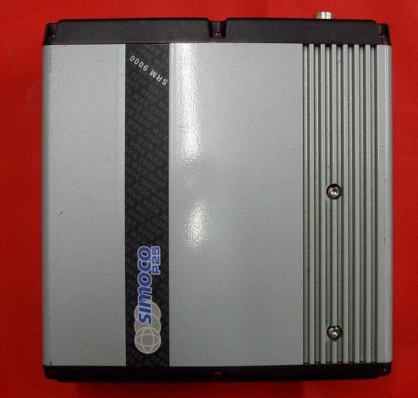
Click to zoom
Application Details
- Equipment Class
- TNB - Licensed Non-Broadcast Station Transmitter
- Date of Grant
- Dec 12, 2012
- Application Purpose
- Original Equipment
- Date of Application
- Dec 12, 2012
- Equipment Note
- VHF MOBILE TRANSCEIVER
- Frequency Range
- 150.00000000 - 174.00000000
- Country
- Australia
Documents & Files
Document Text
Text extracted from the exhibit documents filed with the FCC. Open a document above to read the original.
Users Manual
P25 SRM9030 / SRM9030plus Mobile Radio P25 – Conventional / Trunked Operating Instructions TNM#U#E#0094 Issue 1.2a ComGroup Australia Pty. Ltd. 1270 Ferntree Gully Road Scoresby Victoria, 3179 Australia ISO9001 Li c.QEC20848 S AI Global SRM9030#P25 RADIO – OPERATING INSTRUCTIONS © ComGroup Australia 2010 page 2 TNM-U-E-0094 Issue 1.2 ASSOCIATED DOCUMENTATION The following documentation is available for use with the SRM9000 series of products: TNM-U-E-0079 P25 SRM9030 Mobile Radio Brief User Guide TNM-P-E-0006 P25 SRM9030 Product Manual TNM-I-E-0005 SRM9000 Installation Sheet TNM-M-E-0002 SRM9000 R9 Service Manual To order copies of any of the above publications, or any other ComGroup Australia product, contact ComGroup Australia on +61 3-9730-3800 or send a Fax on +61 3-9730-3968. The ComGroup Australia web site also has a comprehensive list of documentation available for download. http://www.comgroup.net.au ABOUT THIS DOCUMENT This publication is copyright and no part may be reproduced without prior permission of ComGroup Australia. Due to our policy of continuous improvement to our products and services, technical specifications and claims, correct at time of publication, may be subject to variation without prior notice. ComGroup Australia has endeavoured to ensure that the information in this document is fairly and accurately stated, but does not accept liability for any errors or omissions. SRM9030#P25 RADIO – OPERATING INSTRUCTIONS © ComGroup Australia 2010 page 3 TNM-U-E-0094 Issue 1.2 SAFETY 1. Do NOT operate your radio, without a hands free kit, whilst driving a vehicle. 2. Do NOT operate your radio in an explosive atmosphere. Obey the 'Turn Off Two#way Radios' signs where these are posted, e.g. on a petrol station forecourt. 3. Do NOT touch the antenna while the radio is transmitting. HINTS FOR USING THE RADIO • When speaking, hold the microphone a few centimetres from your mouth and speak across it, rather than into it. • Keep the length of your conversation to a minimum and replace the microphone on its cradle after use. • When it is possible to move location, avoid making calls from known poor signal-strength areas such as the radio systems fringe areas (limit of range) or from screened or shadowed areas, e.g. an underground car park or underpass. • To avoid unnecessary drain on the vehicle battery, keep the engine running when using the radio for extensive periods of time. SRM9030#P25 RADIO – OPERATING INSTRUCTIONS © ComGroup Australia 2010 page 4 TNM-U-E-0094 Issue 1.2 CONTENTS 1. INTRODUCTION..................................................................................................6 1.1 Overview ......................................................................................................6 1.2 Configuration ..............................................................................................6 1.3 Modes of P25#SRM9030 Operation ............................................................6 2. CONTROLS .........................................................................................................7 3. MENU SYSTEM .................................................................................................10 3.1 Menu Navigation .......................................................................................12 4. MENU SCREENS ..............................................................................................14 4.1 Channel Screen .........................................................................................14 4.2 Menus.........................................................................................................18 4.2.1 Zone Menu ..............................................................................................18 4.2.2 Squelch ...................................................................................................19 4.2.3 Mute Adjust .............................................................................................21 4.2.4 Phonebook Menu ....................................................................................22 4.2.5 Phonebook Edit Menu .............................................................................23 4.2.6 User Options ...........................................................................................27 4.2.7 Contrast ...................................................................................................28 4.2.8 Alert Volume ............................................................................................29 4.2.9 Radio Information ....................................................................................30 4.2.10 Mode Menu .............................................................................................32 4.2.11 RSSI (Received Signal Strength Indication) ............................................33 4.2.12 Crypto ......................................................................................................34 4.2.13 Setup Menu .............................................................................................35 4.2.14 Stored Calls .............................................................................................36 4.2.15 ....................................................................................................................36 4.2.16 Messages ................................................................................................37 4.2.17 Scan Edit Menu .......................................................................................45 4.2.18 No Menu ..................................................................................................47 5. COMMON FUNCTIONS AND FACILITIES .......................................................48 5.1 Switch#On/Switch#Off ...............................................................................48 5.2 Default Screen –Trunked Mode ..............................................................…
Text truncated - open the document above for the full version.
Users Manual
SRM9030#P25 RADIO – OPERATING INSTRUCTIONS © ComGroup Australia 2010 page 33 TNM-U-E-0094 Issue 1.2 4.2.11 RSSI (Received Signal Strength Indication) This screen displays the received signal strength in dBm. The reading is typically accurate within +/- 2 dBm between -120 and -80dBm, if the radio has been correctly calibrated. For example, -90dBm is a strong signal and –120dBm is no signal. The screen also shows the Bit Error Rate (BER) on digital channels. RSSI and BER are typically used to indicate signal quality. From the Settings Sub Menu, step through the menu options with the ▼ and ▲ keys until the “ RSSI” menu is displayed. Press the “ OK” key for the “RSSI“ screen If a Digital channel is selected BER will be displayed. The RSSI/BER will be displayed until either the “ Menu” key is pressed to return to the next highest menu level or the “ OK” key is pressed which will return to the main channel menu. A lower RSSI value indicates a stronger signal, ie. –80dBm is a stronger signal than –100dBm. SRM9030#P25 RADIO – OPERATING INSTRUCTIONS © ComGroup Australia 2010 page 34 TNM-U-E-0094 Issue 1.2 4.2.12 Crypto This menu allows the digital channel’s default transmit encryption key to be modified. The current selected digital channel has encryption enabled if the padlock symbol is displayed. Press the “ OK” key for the “Crypto Key” menu. Digital Analogue If an Analogue channel is selected, a warning message will display “None-Analog When the Crypto menu is selected, the digital channel’s Encryption Key ID can be changed with the ▼ and ▲ keys. The key name and the key identifier (1-32) for the selected channel is displayed. If the selected channel is changed or the radio is switched off, the channel’s default encryption key will be restored. Pressing the “OK” key returns to the main channel screen. Pressing the “ Back” or “Menu” key returns to the next highest menu level. SRM9030#P25 RADIO – OPERATING INSTRUCTIONS © ComGroup Australia 2010 page 35 TNM-U-E-0094 Issue 1.2 4.2.13 Setup Menu The screens in the Setup sub-menus allow the radio operator to edit/modify the operation of some of the general functions of the radio. Once the Menu key is pressed from the “Channel” screen, the ▼ and ▲ keys cycle through the available “Main” menus. Once the “Setup” menu appears, press the “ OK” key to select it. The ▼ and ▲ keys are then used to scroll through the setup menus. The Setup menu structure may include, for example: • Alert Volume, • Contrast, • RSSI (Received Signal Strength Indication), • Info (Radio software and hardware information), • Crypto (Select Transmit Encryption Key), • Squelch, • Mute Adjust or • User Options SRM9030#P25 RADIO – OPERATING INSTRUCTIONS © ComGroup Australia 2010 page 36 TNM-U-E-0094 Issue 1.2 4.2.14 Stored Calls This screen displays the received individual call records one by one, starting with the most recently received call record. Either the name of the caller from the phone book or the user ID is displayed if the ID is not known to the phone book. If stored calls are empty, NO RECORD is displayed. The ▼ and ▲ keys can be used to step through the stored calls. An error beep will sound if there are no more call records. A “ Reset” function key press (if configured), takes the radio back to the default screen display. The “ Menu” or “Back” key returns to Menu screen. When “OK” key is pressed, a pop up menu is displayed so that the message can be deleted or party called back. The selections are: • DELETE – to delete the call record. • CALL – to call back the caller (set individual call to the caller) • CANCEL – to cancel the action selection. The selection is made with the ▼ and ▲ keys. The “ Menu” or “Back” key returns to Stored Calls screen”. A “Reset” function key press (if configured) takes the radio back to the default screen display. If “ DELETE” is selected, pressing “OK” removes the selected call record (being viewed) from the list. The radio returns to the Stored Calls Screen with the next record being displayed. If “ CANCEL” is selected, the Stored Calls screen is displayed. If “ CALL ” is selected, pressing “ OK ” sets the radio to individual calling mode with the ID of the stored call. A subsequent PTT within the configured time interval will send an individual call to the ID of the stored call. SRM9030#P25 RADIO – OPERATING INSTRUCTIONS © ComGroup Australia 2010 page 37 TNM-U-E-0094 Issue 1.2 4.2.15 Messages A radio unit can receive and transmit predefined short messages and text messages with another radio unit on a digital channel (P25 conventional only). Messages received are stored in radio memory. They can be viewed and deleted as required. If there are unread messages stored in the radio, the envelope icon on the default screen will flash. If there are messages in the radio that have all been read, a steady envelope icon is shown on the default screen. If there are no messages in the radio, the envelope icon will not appear on the default screen. To view/delete/send messages, go to the Menu selection and choose the “ Messages ” menu. When “Messages” is selected from the menu screen with “OK”, a pop-up screen will appear. 4.2.15.1 Messages Selection Pop#Up Menu The pop-up selections are: • VIEW: View received messages. • SMSG: Short Message. The radio can be programmed with a list of predefined messages. Choosing SMSG shows a list of predefined messages, which can be sent as a short message to another radio unit. Only applicable when a digital channel is selected. • TXTMSG: Text message. Enters the text message edit and send sub-menus. Only applicable when a digital channel is selected. Options are selected with the ▼ and ▲ keys. SRM9030#P25 RADIO – OPERATING INSTRUCTIONS © ComGroup Australia 2010 page 38 TNM-U-E-0094 Issue 1.2 Pressing “ Menu ” or “ Back ” keys takes the radio back to the Menu screen. A “ Reset” function key press (if configured) takes the radio back to the default screen display. If “ VIEW ” is selected, pressing “ OK ” shows the …
Text truncated - open the document above for the full version.
Cover Letter(s)
Form Number: FN0024_0 Page 1 of 1 Filename: H:\Standards\FCC\SRM9000 FCC_IC\SRM9000AC Rev 10\STZSRAM9000AC Series 2 FCC Exhibits Word\FCC_SRM9000AC Series 2_authorisation.doc Andrew Cutler EMC Technologies (NZ) Ltd 47 MacKelvie Street Grey Lynn Auckland Ref: Re: STZSRMA9000AC: FCC Equipment Approval 29 October 2012 To Whom It May Concern: Please be advised that ComGroup Australia Pty Ltd authorises EMC Technologies (NZ) Ltd to act on our behalf, until otherwise notified, for applications submitted to the Federal Communications Commission and/or Telecommunications Certification Body. We certify that we are not subject to denial of federal benefits, that includes FCC benefits, pursuant to Section 5301 of the Anti-Drug Abuse Act of 1988, U.S.C. 862. Further, no party to the application, as defined in 47 CFR 1.2002(b), is subject to denial of federal benefits, that includes FCC benefits. Thank you for your attention to this matter. Yours sincerely, Robert Stowell Senior Engineer ComGroup Australia Pty Ltd ABN 29 095 068 429 www.comgroup.net.au 1270 Ferntree Gully Rd, Scoresby Victoria 3179, Australia Tel: +61 3 9730 3800 Fax: +61 3 9730 3968 Email: [email protected]
Cover Letter(s)
Form Number: FN0024_0 Page 1 of 1 Filename: H:\Standards\FCC\SRM9000 FCC_IC\SRM9000AC Rev 10\STZSRAM9000AC Series 2 FCC Exhibits Word\FCC_SRM9000AC Series 2_Confidentiality_Timco_090512.doc Federal Communications Commission 7435 Oakland Mills Road Columbia, MD 21046 Timco Engineering Inc 849 N.W. State Road 45 PO Box 370 Newberry Florida 32669 Ref: Re: STZSRMA9000AC: FCC Equipment Approval Confidentiality 29 October 2012 To Whom It May Concern: The following information is to be held confidential pursuant of 47 CFR Part 0 §0.459 and Section 552(b)(4) of the Freedom of Information Act, because the information provided contains trade secrets and is proprietary. If made public, the information might be used to the disadvantage of the applicant in the market place. • Schematics • Operational Description • Block Diagram • Parts List • Tune Up Instruction • User Manual [NOTE: This request is for the “Technical” manual that is used as a service manual by authorised personnel and contains detailed technical information including operational descriptions and Tune Up information]. Yours sincerely, Robert Stowell Senior Engineer ComGroup Australia Pty Ltd ABN 29 095 068 429 www.comgroup.net.au 1270 Ferntree Gully Rd, Scoresby Victoria 3179, Australia Tel: +61 3 9730 3800 Fax: +61 3 9730 3968 Email: [email protected]
Cover Letter(s)
Form Number: FN0024_0 Page 1 of 1 Filename: H:\Standards\FCC\SRM9000 FCC_IC\SRM9000AC Rev 10\STZSRAM9000AC Series 2 FCC Exhibits Word\FCC_SRM9000 AC Series 2_Extended Frequency Justification_181012.doc Timco Engineering Inc 849 N.W. State Road 45 PO Box 370 Newberry Florida 32669 Ref: Re: STZSRMA9000AC: Extended Frequency Justification 29 October 2012 Dear Sir/ Madam, ComGroup Australia would like to submit the following justification to show the frequency range as 150 – 174 MHz on the Grant of Equipment Authorization for STZSRMA9000AC equipment. This frequency range is applicable to FCC Part 90 radiocommunication systems that would include federal and public agencies, emergency services, commercial, business and industrial services etc. These services account for the majority of users on this band (refer to the list below). Frequency: Application: 150.05 – 150.8 Federal Government 150.8 – 156.2475 Part 90 157.1875 – 161.575 Part 90 161.625 – 173.4 Federal Government and Part 90 173.4 – 174 Federal Government Also the frequency of operation of the STZSRMA9000AC mobile radio cannot be programmed by the operator to transmit on frequencies other than those programmed by service or maintenance personnel. From the FCC KDB634187 guide, it is noted that FCC rules would be violated if the STZSRMA9000AC equipment were programmed and operated on unauthorized frequencies. Sincerely, Robert Stowell Senior Engineer ComGroup Australia Pty Ltd ABN 29 095 068 429 www.comgroup.net.au 1270 Ferntree Gully Rd, Scoresby Victoria 3179, Australia Tel: +61 3 9730 3800 Fax: +61 3 9730 3968 Email: [email protected]
Cover Letter(s)
Form Number: FN0024_0 Page 1 of 1 Filename: H:\Standards\FCC\SRM9000 FCC_IC\SRM9000AC Rev 10\STZSRAM9000AC Series 2 FCC Exhibits Word\FCC_SRM9000AC Series 2_Frequency Programming_Timco.doc Timco Engineering Inc 849 N.W. State Road 45 PO Box 370 Newberry Florida 32669 Ref: Re: STZSRMA9000AC: 47 CFR Part 90.203(e) Compliance 29 October 2012 To Whom It May Concern: The frequency of operation of the STZSRMA9000AC mobile radio cannot be programmed by the operator to transmit on frequencies other than those programmed by service or maintenance personnel. The STZSRMA9000AC radio requires the operating frequencies to be programmed through the use of an external device only available to service or maintenance personnel. Yours sincerely, Robert Stowell Senior Engineer ComGroup Australia Pty Ltd ABN 29 095 068 429 www.comgroup.net.au 1270 Ferntree Gully Rd, Scoresby Victoria 3179, Australia Tel: +61 3 9730 3800 Fax: +61 3 9730 3968 Email: [email protected]
Cover Letter(s)
Form Number: FN0024_0 Page 1 of 1 Filename: H:\Standards\FCC\SRM9000 FCC_IC\SRM9000AC Rev 10\STZSRAM9000AC Series 2 FCC Exhibits Word\FCC_SRM9000AC Series 2_PA_Timco.doc Timco Engineering Inc 849 N.W. State Road 45 PO Box 370 Newberry Florida 32669 Ref: Re: STZSRMA9000AC: 47 CFR Part 2.1033(c)(8) 29 October 2012 To Whom It May Concern: The DC voltage applied to the final stages of the Radio Frequency amplifier of the STZSRMA9000AC mobile transceiver is nominally 13.8 volts and the DC current into the final stages is typically 5.0 amps. Yours sincerely, Robert Stowell Senior Engineer ComGroup Australia Pty Ltd ABN 29 095 068 429 www.comgroup.net.au 1270 Ferntree Gully Rd, Scoresby Victoria 3179, Australia Tel: +61 3 9730 3800 Fax: +61 3 9730 3968 Email: [email protected]
Cover Letter(s)
ComGroup Australia Pty Ltd ABN 29 095 068 429 www.comgroup.net.au 1270 Ferntree Gully Rd, Scoresby Victoria 3179, Australia Tel: +61 3 9730 3800 Fax: +61 3 9730 3968 Email: [email protected] NON DISCLOSURE AGREEMENT BETWEEN: ComGroup Australia Pty. Ltd. 1270 Ferntree Gully Road Scoresby Victoria 3179 Australia AND: (Purchaser/ Recipient Details) SUBJECT OF AGREEMENT: SRM9000 Series 2 Rev 10 Service Manual Issue 1.0 Confidential Information CONFIDENTIALITY: This SRM9000 Series 2 Service Manual contains information that, should it become public, might be used to disadvantage ComGroup Australia Pty. Ltd. in the market place. The information contained in the Service Manual is the confidential information of ComGroup Australia Pty. Ltd. and at all times remains their property. The recipient of this information shall not use, copy, abstract or disclose any information it receives or anything it learns as a result of the information to any other person, firm, corporation or other entity without the express consent of ComGroup Australia. Dissemination of the information by the recipient shall be limited to the recipient’s employees who have a need to know and who shall be bound to honor the provisions of this Agreement. EXCEPTIONS. The obligation of confidentiality shall not apply to any information which: (a) is contained in a generally available non-confidential publication bearing a date prior to the date of this agreement; (b) is or becomes generally available to the public other than as a result of the improper action of the recipient. USE OF INFORMATION. All information shall be used by the recipient solely for the purpose of support for ComGroup Australia Pty. Ltd. products and services. The parties acknowledge that they have read and understood this agreement and agree to be bound by its terms Date Date: Signed Signed: Name (Print) Name (Print) Company Name ComGroup Australia Pty. Ltd. Company Name Purchaser/ Recipient Position Position
Cover Letter(s)
Form Number: FN0024_0 Page 1 of 1 Filename: H:\Standards\FCC\SRM9000 FCC_IC\SRM9000AC Rev 10\STZSRAM9000AC Series 2 FCC Exhibits Word\FCC_SRM9000AC Series 2_Spectrum_Efficiency_Timco.doc Timco Engineering Inc 849 N.W. State Road 45 PO Box 370 Newberry Florida 32669 Ref: Re: STZSRMA9000AC: 47 CFR Part 90.203(j)(3) Compliance 29 October 2012 To Whom It May Concern: This is to certify that the requirements of 47 CFR Part 90.203(j)(3) spectrum efficiency standard of one voice channel per 12.5kHz of channel bandwidth are met by the STZSRMA9000AC mobile radio as demonstrated by the tests conducted on the sample radio provided (11k0F3E emission). Additionally in this sample, the C4FM data rate is in accordance with TIA-102, that is 9600 bits per second in a 12.5kHz channel bandwidth, therefore the STZSRMA9000AC transmitted data satisfies the requirement of 4800 bits per second per 6.25kHz of channel bandwidth for 8K10F1E and 8K10F1D emissions. Yours sincerely, Robert Stowell Senior Engineer ComGroup Australia Pty Ltd ABN 29 095 068 429 www.comgroup.net.au 1270 Ferntree Gully Rd, Scoresby Victoria 3179, Australia Tel: +61 3 9730 3800 Fax: +61 3 9730 3968 Email: [email protected]
External Photos
____________________________________________________________________________________________________________________________________________________________________________ Page 23 of 33 Test Report No 121018.1 29 th November 2012. This report may not be reproduced except in full. 10. PHOTOGRAPH (S) ____________________________________________________________________________________________________________________________________________________________________________ Page 24 of 33 Test Report No 121018.1 29 th November 2012. This report may not be reproduced except in full. MAR-9030PLCH control head MAR-9022CM control head MAR-9020plus control head ____________________________________________________________________________________________________________________________________________________________________________ Page 25 of 33 Test Report No 121018.1 29 th November 2012. This report may not be reproduced except in full. Label Label on bottom of transceiver
ID Label/Location Info
MAR-9030PLCH control head MAR-9030PLCH control head
ID Label/Location Info
____________________________________________________________________________________________________________________________________________________________________________ Page 25 of 33 Test Report No 121018.1 29 th November 2012. This report may not be reproduced except in full. Label Label on bottom of transceiver
Internal Photos
____________________________________________________________________________________________________________________________________________________________________________ Page 32 of 33 Test Report No 121018.1 29 th November 2012. This report may not be reproduced except in full. Internal Photos ____________________________________________________________________________________________________________________________________________________________________________ Page 33 of 33 Test Report No 121018.1 29 th November 2012. This report may not be reproduced except in full.
RF Exposure Info
____________________________________________________________________________________________________________________________________________________________________________ Page 21 of 33 Test Report No 121018.1 29 th November 2012. This report may not be reproduced except in full. Exposure of humans to RF fields As per Section 1.1310 mobile transmitters are required to be operated in a manner that ensures the public is not exposed to RF energy levels in accordance with OST/OET Bulletin Number 65. Calculations have been made using the General Public/Uncontrolled Exposure limits. Minimum safe distances have been calculated below. Power density, mW/m 2 = E 2 /3770 - Occupational / Controlled Exposure limit will be 10 mW/m 2 or 60 V/m - General Population / Uncontrolled exposure limit will be 2 mW/m 2 or 28 V/m The minimum distance from the antenna at which the MPE is met is calculated from the equation relating field strength in V/m, transmit power in watts, transmit antenna gain, transmitter duty cycle and separation distance in metres: E, V/m = (√(30 * P * G)) / d The rated maximum transmitter power = 25 watts. Transmitter is operated using a quarter wave whip antenna with a gain of 2.14 dBi (1.64). As the transmitter is used on a push to talk basis a duty cycle of 50% has been applied. Controlled Uncontrolled d = √ (30 * P * G*DC) / E d = √ (30 * 25 * 1.64 * 0.50) / 60 d = √ (30 * 25 * 1.64 * 0.50) / 28 d = 0.41 metres or 41 cm d = 0.89 metres or 89 cm Result: Complies if the safe distances defined for each environment are applied.
Test Report
____________________________________________________________________________________________________________________________________________________________________________ Page 1 of 33 Test Report No 121018.1 29 th November 2012. This report may not be reproduced except in full. EMC Technologies (NZ) Ltd PO Box 68-307 Newton, Auckland Phone 09 360 0862 Fax 09 360 0861 E-Mail Address: [email protected] Web Site: www.emctech.com.au TEST REPORT SIMOCO SRM9000 AC, Series 2, VHF Mobile Transceiver Tested to the Code of Federal Regulations (CFR) 47 Part 90 –Private Land Mobile Services for ComGroup Australia Pty Ltd This Test Report is issued with the authority of: ______________________________________ Andrew Cutler - General Manager ____________________________________________________________________________________________________________________________________________________________________________ Page 2 of 33 Test Report No 121018.1 29 th November 2012. This report may not be reproduced except in full. Table of Contents 1. STATEMENT OF COMPLIANCE 3 2. RESULTS SUMMARY 3 3. INTRODUCTION 4 4. CLIENT INFORMATION 4 5. DESCRIPTION OF TEST SAMPLE 4 6. ATTESTATION 6 7. TEST RESULTS 7 8. TEST EQUIPMENT USED 22 9. ACCREDITATIONS 22 10. PHOTOGRAPH (S) 23 ____________________________________________________________________________________________________________________________________________________________________________ Page 3 of 33 Test Report No 121018.1 29 th November 2012. This report may not be reproduced except in full. 1. STATEMENT OF COMPLIANCE The SIMOCO SRM9000 AC, Series 2, VHF Mobile Transceiver complies with the limits defined in 47 CFR Part 90 and 47 CFR Part 2 when tested in-accordance with the test methods described in 47 CFR Part 2. 2. RESULTS SUMMARY The results of testing carried out between 16 th November and 30 th November 2012 are summarised below. Clause Description Result 90.203 Certification required Noted 2.1046 90.205 RF power output Power and antenna height limits Noted Complies 2.1047 2.1047(a) 2.1047(b) 90.211(a) Modulation Characteristics Low pass filter response Modulation limiting characteristics Modulation characteristics Noted Noted Noted Complies 2.1049 2.202 90.207 90.209 90.210 Occupied bandwidth Bandwidths Types of emissions Bandwidth limitations Emission masks Noted Noted Complies Complies Complies 2.1051 Spurious emissions at antenna terminals Complies 2.1053 Field strength of spurious radiation Complies 2.1055 90.213 Frequency stability Frequency stability Noted Complies 90.214 Transient frequency behaviour Complies 1.1310 Radio frequency exposure limits Complies ____________________________________________________________________________________________________________________________________________________________________________ Page 4 of 33 Test Report No 121018.1 29 th November 2012. This report may not be reproduced except in full. 3. INTRODUCTION This report describes the tests and measurements performed for the purpose of determining compliance with the specification. The client selected the test sample. This report relates only to the sample tested. This report contains no corrections or erasures. Measurement uncertainties with statistical confidence intervals of 95% are shown below test results. Both Class A and Class B uncertainties have been accounted for, as well as influence uncertainties where appropriate. 4. CLIENT INFORMATION Company Name ComGroup Australia Pty Ltd Address 1270 Ferntree Gully Rd, Scoresby, Victoria, 3179 Country Australia Contact Mr Bob Stowell 5. DESCRIPTION OF TEST SAMPLE Brand Name SIMOCO Model Number SRM9000 AC Product Series 2, VHF Mobile Transceiver Manufacturer ComGroup Australia Manufactured in Taiwan Designed in Australia Serial Numbers ERACX12281234 FCC ID STZSRMA9000AC ____________________________________________________________________________________________________________________________________________________________________________ Page 5 of 33 Test Report No 121018.1 29 th November 2012. This report may not be reproduced except in full. The sample tested has the following specifications: Rated Transmitter Output Power 25.0 Watts (43.9 dBm) Transmitter FCC frequency range 150 - 174 MHz Test frequencies Chl Frequency MHz Power Watts Spacing kHz 1 150.175 (F3E) 25.0 12.5 2 162.175 (F3E) 25.0 12.5 3 173.975 (F3E) 25.0 12.5 4 150.175 (P25) 25.0 12.5 5 162.175 (P25) 25.0 12.5 6 173.975 (P25) 25.0 12.5 FCC Bands Part 90: 150 - 174 MHz Emission Designators / Modes of operation 11k0F3E – Analogue speech 8k10F1E – C4FM digital speech 8k10F1D – C4FM data transmission Power Supply Lead acid battery DC voltage supply typically 12.0 Vdc Standard Temperature and Humidity Temperature: +15C to + 30 maintained. Relative Humidity: 20% to 75% observed. Standard Test Power Source Standard Test Voltage: 13.8 Vdc. High Voltage: 15.6 Vdc Low Voltage: 10.8 Vdc Extreme Temperature High Temperature: + 50C maintained. Low Temperature: - 30 C maintained. ____________________________________________________________________________________________________________________________________________________________________________ Page 6 of 33 Test Report No 121018.1 29 th November 2012. This report may not be reproduced except in full. 6. AT T E S TAT I O N The SIMOCO SRM9000 AC, Series 2, VHF Mobile Transceiver complies with the Code of Federal Regulations (CFR) 47 Part 90 – Private La…
Text truncated - open the document above for the full version.
Contact Information
Applicant
Barend Gildenhuys(Mr)
Test Firm
EMC Technologies NZ Ltd.Andrew Cutler
Technical Specifications
| # | Rule Parts | Frequency Range | Power Output | Emission | Tolerance |
|---|---|---|---|---|---|
| 3 | 9 | 150 MHz - 174 MHz | 25 W | 8K10F1E | 5 ppm |
Other Applications from Simoco Wireless Solutions Pty Ltd
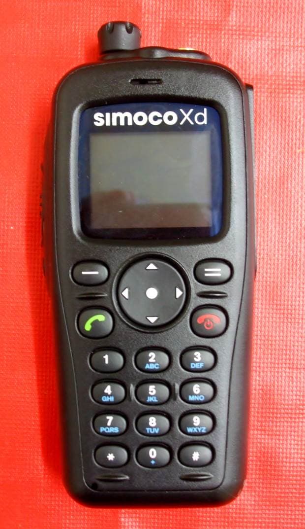
STZSDP600UW
Jun 14, 2015UHF Portable Transceiver
Equipment Class
TNB - Licensed Non-Broadcast Station Transmitter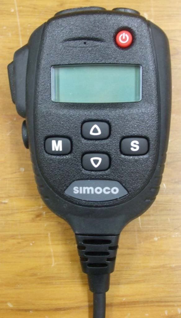
STZSDM600UW
Oct 24, 2013UHF MOBILE TRANSCEIVER
Equipment Class
TNB - Licensed Non-Broadcast Station Transmitter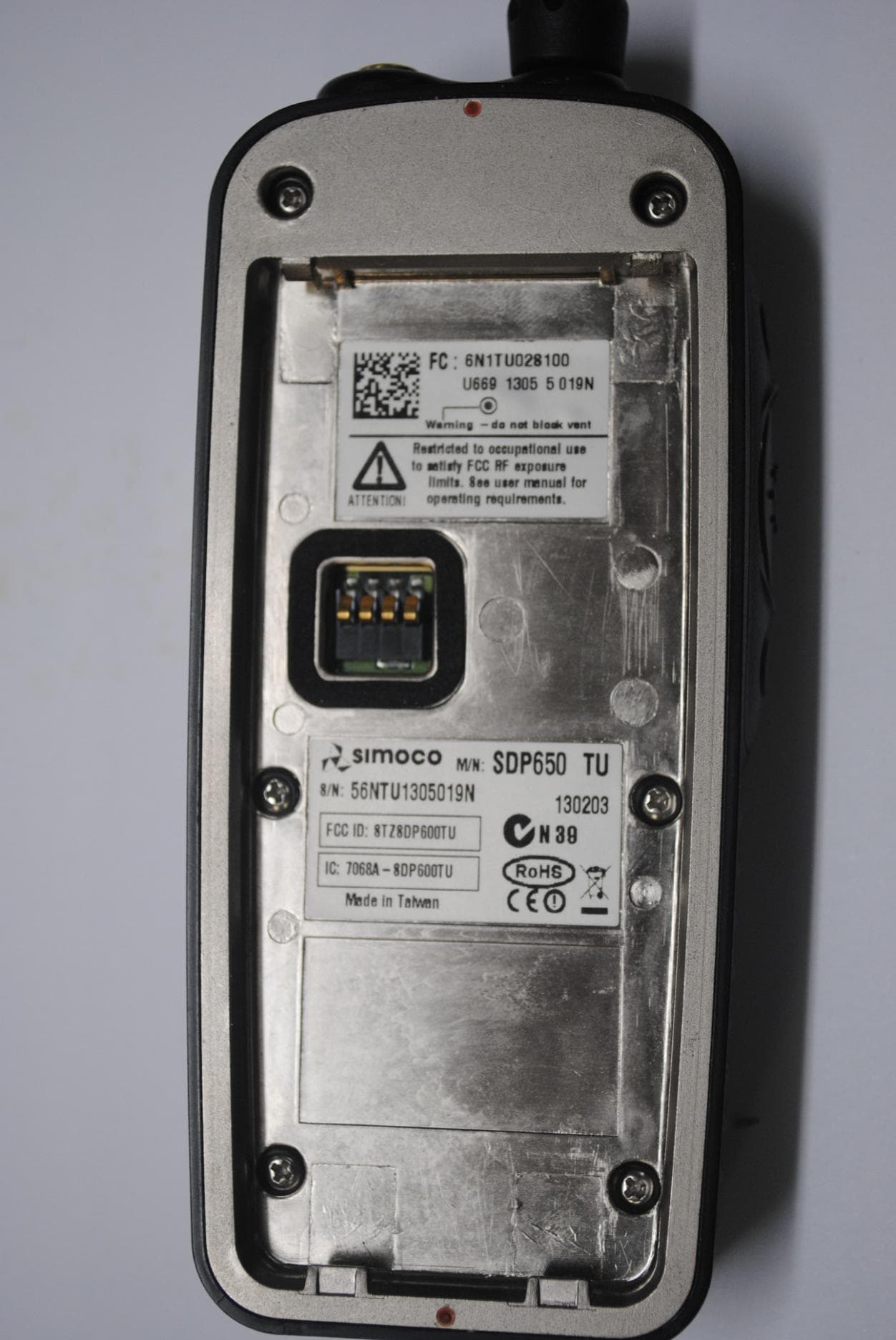
STZSDP600TU
Sep 10, 2013SDP600TU series UHF PMR/DMR Portable Transceiver
Equipment Class
TNF - Licensed Non-Broadcast Transmitter Held to Face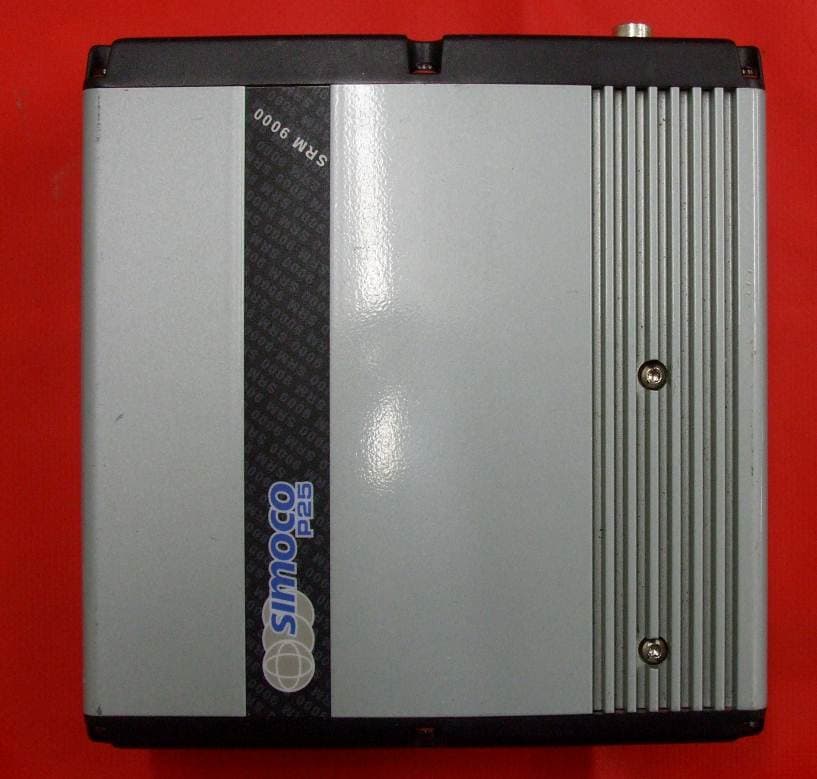
STZSRMA9000TU
Dec 13, 2012UHF MOBILE TRANSCEIVER
Equipment Class
TNB - Licensed Non-Broadcast Station Transmitter
STZSRMA9000UW
Dec 11, 2012UHF MOBILE TRANSCEIVER
Equipment Class
TNB - Licensed Non-Broadcast Station Transmitter