SU3RM2400RAE Mesh Module
RAE Systems, Inc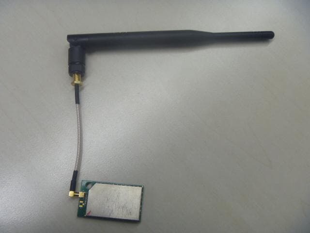
Click to zoom
Application Details
- Equipment Class
- DTS - Digital Transmission System
- Date of Grant
- Apr 02, 2015
- Application Purpose
- Original Equipment
- Date of Application
- Mar 31, 2015
- Equipment Note
- RAE Mesh Module
- Frequency Range
- 2405.00000000 - 2475.00000000
- Company
- RAE Systems, Inc
- Country
- United States
Documents & Files
Document Text
Text extracted from the exhibit documents filed with the FCC. Open a document above to read the original.
Users Manual
RAEMesh2 User Manual Doc.No: Originator: kren Page 1 of 21 Data: 2014-3-18 RAEMesh2 Radio User Manual RAE Systems Inc RAEMesh2 User Manual Doc.No: Originator: kren Page 2 of 21 Data: 2014-3-18 Revision Date Comments Author 0.1 11/28/2008 Initial Alven 0.2 12/1/2008 Add “Radio Core Setting Procedure” Alven 0.3 1/4/2009 Add “Fuse config”, “Firmware programmer” Alven 0.4 1/5/2009 Add “Soft Reset” command Alven 0.5 3/26/2010 Add “Reset reason” command kren 0.6 4/22/2010 Add description about TXPOWER and Channel setting kren 0.7 5/20/10 Add START_ROUTING command. Change SET_FACTORY_RST for RM2400 kren 0.8 5/25/10 Add RAEMesh and RAEMesh-II difference, CHG START_ROUTING to SET_ROUTEINTERVAL, add GET_ROUTEINTERVAL and SET_REGION. kren 0.9 8//17/10 Modify ModuleType definition. kren 1.0 10/14/10 Add modem longest startup time; Add modem longest packet length from SOP to EOP; rename “RFD” as “STD”, rename “FFD” as “RTR”, rename “Coordinator” as “GTW”. kren 1.1 11/19/10 Error, best rssi of at command response is 240, not 100. kren 1.2 01/31/11 Add new command, GET_FWVERSION kren 1.3 03/25/11 Add new commands, SET_CMDBATCH and GET_CMDBATCH kren 1.4 04/07/11 Modify GET_PARENT_ID definition. Modem return 0x5b 24 27 5d when it transmit a pack and get acknowledge successfully. kren 1.5 6/28/2011 Add SET_BOOTLOADER kren 11/25/2011 Add bootloader section kren 5/8/2012 Add RM900A module type. Add SAM7X RAELoader Section Add RM900A low temperature current comsumption. kren 5/23/2012 Add RM2400, RM2400M, RM900AM, Wifi and Cellular modem type. kren 8/16/2013 Modify FACTORY_RESET. kren 9/23/13 Add GET_TRIAL_INFO kren 1/23/14 Add Wi-Fi related command Wu Wei 2/18/14 Add three commands, SYS_CTRL_GET, SYS_CTRL_SET, SEC_KEY_SET kren 04/03/14 Delete Wi-Fi related command Wu Wei 4/3/2014 Add GET_NEIGHBOUR_LIST kren RAEMesh2 User Manual Doc.No: Originator: kren Page 3 of 21 Data: 2014-3-18 1. Introduction The RAEMesh Radio module offers a complete microcontroller/transceiver solution Containing all hardware features necessary for development of a low data-rate, low-power wireless application. The primary components include an IEEE 802.15.4 compliant Zigbee-ready transceiver , a microcontroller, a 40-pin interface connector, a MMCS antenna connector, This documentation describes the RAEMesh radio module hardware interface as well as RAE System’s Command Interface. 2. Hardware 1) Specifications Frequency Band 2.4Ghz: 15 channels of operation in the 2.4GHz world wide ISM band. 5MHz channel spacing. Power +3.3V + .3V from carrier board, 3.0V to 3.6V from battery pack Interfaces 40-pin surface-mount 2x20 1.27mm pitch RF 250kbps OQPSK Direct Sequence Spread Spectrum @2.4GHz Dimensions 46.5 mm x 26 mm x 10 mm Antenna Interface 50-Ohm MMCX female Operating Temperature Range -40ºC to +85ºC Indicators Two LEDs 2) Pin Layout Pin Description Pin Description 1 DGND 2 DGND 3 nRESET 4 DGND 5 TXD1 6 TXD0/Bootload. 7 RXD1 8 RXD0 9 GPIO0 10 GPIO/LED2 11 GPIO1 12 GPIO/LED3 13 GPIO2 14 GPIO/LED4 15 GPIO3 16 GPIO/LED5 17 TEMP_E/GPIO4 18 GPIO/PS_CS 19 WakeUp/GPIO5 20 GPIO/PS_FRAME 21 BUZZER/GPIO6 22 +3.3V 23 GPIO7/PS_DIR 24 AGND RAEMesh2 User Manual Doc.No: Originator: kren Page 4 of 21 Data: 2014-3-18 25 BUTTON0/GPIO8 26 AREF 27 BUTTON1/GPIO9 28 ATEMP/ADC1 29 GPIO10 30 ADC2 31 RF_SO 32 TCK 33 RF_SI 34 TMS 35 RF_CK 36 TDO 37 SFD 38 TDI 39 +3.3V 40 +3.3V 3. Mechanical Size Top View RAEMesh2 User Manual Doc.No: Originator: kren Page 5 of 21 Data: 2014-3-18 The height of the shielding box is 4.3mm from the PCB. 40 Pin header (1.27mm) is used for board to board connection. Corresponding mate connector can be JVE 22P8702-40M00B-01G-4.5 4. Firmware The module is pre-loaded with the bootloader, which supports serial bootloading of firmware update. The module contains RAEMesh application and comply with the RAE System’s RCS protocol. The module also has built-in RAEMesh Module Command Interface(RMCI). This documentation is focused on the instruction on RMCI interface. The RMCI command interface allows customer to easily access to low level mesh functionality without pain to develop the firmware. The module can be configured to a GTW to hook up to a getaway or just a stand alone regular full function node or a Sleepy reduce function node. Make sure to configure the module to right mode before using. 1) Quick Start UART Via the TXD1 and RXD1 pins the command interpreter can be accessed. The RCM can buffer up to 128 bytes of incoming data in a software FIFO buffer and uses XON/XOFF flow control. See the datasheet of the Atmel ATmega1281 for more information about the build-in UART. Connect Pin5 (TXD1) and Pin7 (RXD1) to the customer board. Use the following settings for serial port. RTR and STD: 19200bps, 8N1. GTW: 38400bps, 8N1. Data Packet RCM will transmit any data in the { }, all data in the {} will be transparently sent out without radio’s interpretation. The maximum data packet is 90 bytes including {}. The data in the {} can be any characters including ‘{‘ ‘}’ ’[‘ ’]’ . The interval between 2 data packets must be >200ms for RTR and GTW. The interval between 2 data packets must be >1s for STD. Wakeup If the radio is set to STD mode, the Wakeup pin Pin19 (PE7) is used to make the radio asleep and wakeup. A constant high on this pin will let the radio go to the sleep mode and a low level signal on this pin will wake-up the radio. The Radio sleep mode is the power save mode so the power consumption can be very low. (<40uA) RAEMesh2 User Manual Doc.No: Originator: kren Page 6 of 21 Data: 2014-3-18 The Wakeup pin must be held up to 10ms before sending a data packet. Power Ground: Pin1, Pin2 and Pin4. VCC: Pin39, Pin40. 3.0V or 3.3V Heartbeat Connect Pin12 to a LED for heartbeat indicator. Reset. RST: Pin3 Active Low. PC communication Please has your serial port debug software installed on the PC. For example: sscom32.exe Microsoft Hyper Terminal is not recommended for this application because it is not good to send characters and commands in Hex. …
Text truncated - open the document above for the full version.
Cover Letter(s)
Date: _02-25-2015__ American Certification Body, Inc. 6731 Whittier Avenue Suite C110 McLean, VA 22101 To Whom It May Concern: ______ Intertek Testing Services Shanghai _____ is authorized to act on our behalf, until otherwise notified, for applications to RAE Systems, Inc. We certify that we are not subject to denial of federal benefits, that includes FCC benefits, pursuant to Section 5301 of the Anti-Drug Abuse Act of 1988, 21 U.S.C. 862. Further, no party, as defined in 47 CFR 1.2002 (b) , to the application is subject to denial of federal benefits, that includes FCC benefits. Thank you, Agency Agreement Expiration Date: _____02-25-2016_____ By: __________________________ ________________________ (Signature 1 ) (Print name) Title: _Engineering Director---Wireless_ On behalf of: _____RAE Systems Inc_____ (Company Name) Telephone: ________408-9528200________ 1 - Must be signed by applicant contact given for applicant on the FCC site, or by the authorized agent if an appropriate authorized agent letter has been provided. Letters should be placed on appropriate letterhead.
Cover Letter(s)
Request for Confidentiality Date: _02-25-2015_ Subject: Confidentiality Request for: _FCC ID: SU3RM2400_ Pursuant to FCC 47 CRF 0.457(d) and 0.459 and IC RSP-100, Section 10, the applicant requests that a part of the subject FCC application be held confidential. Type of Confidentiality Requested Exhibit Short Term Permanent Block Diagrams Short Term External Photos Short Term Permanent* 1 Internal Photos Short Term Permanent Operation Description/Theory of Operation Short Term Permanent Parts List & Placement/BOM Short Term Permanent Tune-Up Procedure Short Term Permanent Schematics Short Term Test Setup Photos Short Term Permanent* User’s Manual *Note: ______(Insert Explanation as Necessary)______ _____RAE Systems Inc ____ has spent substantial effort in developing this product and it is one of the first of its kind in industry. Having the subject information easily available to "competition" would negate the advantage they have achieved by developing this product. Not protecting the details of the design will result in financial hardship. Permanent Confidentiality: The applicant requests the exhibits listed above as permanently confidential be permanently withheld from public review due to materials that contain trade secrets and proprietary information not customarily released to the public. Short-Term Confidentiality: The applicant requests the exhibits selected above as short term confidential be withheld from public view for a period of _ ___ days from the date of the Grant of Equipment Authorization and prior to marketing. This is to avoid premature release of sensitive information prior to marketing or release of the product to the public. Applicant is also aware that they are responsible to notify ACB in the event information regarding the product or the product is made available to the public. ACB will then release the documents listed above for public disclosure pursuant to FCC Public Notice DA 04-1705. NOTE for Industry Canada Applications: The applicant understands that until such time that IC distinguishes between Short Term and Permanent Confidentiality, either type of marked exhibit above will simply be marked Confidential when submitted to IC. Sincerely, By: __________________________ ________________________ (Signature/Title 2 ) (Print name) 1 - The asterisked items (*) require further justification before permanent confidentiality will be allowed. These also currently require review by the FCC under their Permit-But-Ask policy before the grant is issued and can delay completion of an application. Further justification should be added to the note above. One such example for a potted device would be: “The EUT is FULLY potted using a non-removable epoxy based material. Removal of potting material causes irreparable damage to internal circuitry. See photographs exhibits that outline the device before and after potting.” 2 - Must be signed by applicant contact given for applicant on the FCC site, or by the authorized agent if an appropriate authorized agent letter has been provided. Letters should be placed on appropriate letterhead.
Cover Letter(s)
Modular Approval Request Letter FCC ID: SU3RM2400 Data: 2015/02/25 Gentlemen: There’s a RM2400 (RAE Mesh Module) that would like to have your authorization as a modular approval. The specific product as below, RM2400, with its designed features and specified description, meets special requirements for full modular approval on FCC Public Notice KDB996369 Released: October 31, 2013 by cross-reference list below. Company : RAE Systems Inc Model Name : RAE Mesh Module Model Number : RM2400 FCC ID : SU3RM2400 Requirement of KDB996369 Reference to 1. The radio elements must have the radio frequency circuitry shielded. Physical components and tuning capacitor(s) may be located external to the shield, but must be on the module assembly; The module has its own RF shielding. 2. The module must have buffered modulation/data inputs to ensure that the device will comply with Part 15 requirements with any type of input signal; RM2400 has only digital I/Os for data input or output. All these inputs are buffered in MCU. Please see the schematic.pdf. 3. The module must contain power supply regulation on the module; The RM2400 contains power supply regulation chip (U10) on the module. Please see the SU3RM2400_SCH.pdf. 4. The module must contain a permanently attached antenna, or contain a unique antenna connector, and be marketed and operated only with specific antenna(s), per Sections 15.203, 15.204(b), 15.204(c), 15.212(a), 2.929(b); The RM2400 meets the FCC antenna requirements. It has a unique MMCX connector and need special cable to connect to antenna. 5. The module must demonstrate compliance in a stand-alone configuration; The RM2400 was tested in a stand-alone configuration. 6. The module must be labelled with its permanently affixed FCC ID label, or use an electronic display (See KDB Publication 784748 about labelling requirements); The label position of RM2400 clearly indicated. Please see the “SU3RM2400_FCC label.pdf”. 7. The module must comply with all specific rules applicable to the transmitter including all the conditions provided in the integration instructions by the grantee; The RM2400 is compliant with all applicable FCC rules. Detail instructions are given in the Users Manual. Please see users manual.pdf. 8. The module must comply with RF exposure requirements. The RM2400 comply with applicable RF exposure requirements. Thank you. Director, Wireless System Product RAE Systems Inc TEL: 408-952800 Email: [email protected]
External Photos
FCC ID: SU3RM2400 Page 1 of 2 External Picture FCC ID: SU3RM2400 Page 2 of 2 EUT
ID Label/Location Info
FCC ID: SU3RM2400 FCC ID Label FCC ID: SU3RM2400 Label
Internal Photos
FCC ID: SU3RM2400 Page 1 of 7 Internal Picture FCC ID: SU3RM2400 Page 2 of 7 FCC ID: SU3RM2400 Page 3 of 7 FCC ID: SU3RM2400 Page 4 of 7 FCC ID: SU3RM2400 Page 5 of 7 FCC ID: SU3RM2400 Page 6 of 7 FCC ID: SU3RM2400 Page 7 of 7
RF Exposure Info
FCC ID: SU3RM2400 Page 1 of 2 Statement of compliance to Maximum Permissible Exposure (MPE) Applicant : RAE Systems Inc. 3775 N. 1st St., San Jose, California USA 95134 Manufacturer : RAE Systems Inc. 3775 N. 1st St., San Jose, California USA 95134 Product Name : RAE Mesh Module Type/Model : RM2400 According to §2.1091, §2.1093 and §1.1307(b), systems operating under the provisions of this section shall be operated in a manner that ensures that the public is not exposed to radio frequency energy level in excess of the Commission’s guidelines. The S = PG / (4πR²) Where S = power density in mW/cm² P = transmit power in mW G = numeric gain of transmit antenna R = distance (cm) As we can see from the test reports 141201505SHA-001: The maximum output power = 9.12dBm, G=1.50dBi The MPE of Bluetooth = PG / (4πR²) = 11.53mW / (4 * 3.14 * 20 * 20) = 0.0023mW/cm² This level is below the simultaneous transmission MPE test exclusion requirements (≤1.0). Date of issue: March 2, 2015 Prepared by: Reviewed by: Nemo Li (Project Engineer) Daniel Zhao (Reviewer) FCC ID: SU3RM2400 Page 2 of 2 Appendix I Definition below must be outlined in the User Manual: To satisfy FCC RF exposure requirements, a separation distance of 20 cm or more should be maintained between the antenna of this device and persons during device operation. To ensure compliance, operations at closer than this distance is not recommended.
Test Report
FCC ID: SU3RM2400 Page 1 of 33 EMC TEST REPORT for Intentional Radiator No. 141201505SHA-001 Applicant : RAE Systems Inc. 3775 N. 1st St., San Jose, California USA 95134 Manufacturer : RAE Systems Inc. 3775 N. 1st St., San Jose, California USA 95134 Product Name : RAE Mesh Module Type/Model : RM2400 SUMMARY The equipment complies with the requirements according to the following standard(s): 47CFR Part 15 (2014): Radio Frequency Devices(Subpart C) ANSI C63.4 (2009): American National Standard for Methods of Measurement of Radio- Noise Emissions from Low-Voltage Electrical and Electronic Equipment in the Range of 9 kHz to 40 GHz Date of issue: March 2, 2015 Prepared by: Reviewed by: Nemo Li (Project Engineer) Daniel Zhao (Reviewer) FCC ID: SU3RM2400 Page 2 of 33 Description of Test Facility Name: Intertek Testing Services Limited Shanghai Address: Building 86, No. 1198 Qinzhou Rd., North, Shanghai 200233, P.R. China FCC Registration Number: 236597 IC Assigned Code: 2042B-1 Name of contact: Jonny Jing Tel: +86 21 61278271 Fax: +86 21 54262353 FCC ID: SU3RM2400 Page 3 of 33 Content SUMMARY .......................................................................................................................................................... 1 DESCRIPTION OF TEST FACILITY ......................................................................................................................... 2 1. GENERAL INFORMATION ............................................................................................................................ 4 1.1 Applicant Information ..................................................................................................... 4 1.2 Identification of the EUT ................................................................................................ 4 1.3 Technical specification ................................................................................................... 5 2. TEST SPECIFICATION .................................................................................................................................. 6 2.1 Instrument list ................................................................................................................. 6 2.2 Test Standard .................................................................................................................. 7 2.3 Mode of operation during the test / Test peripherals used .............................................. 8 2.4 Test Summary ................................................................................................................. 9 3. MINIMUM 6DB BANDWIDTH ..................................................................................................................... 10 3.1 Limit .............................................................................................................................. 10 3.2 Test Configuration ........................................................................................................ 10 3.3 Test Procedure and test setup ........................................................................................ 10 4. MAXIMUM PEAK OUTPUT POWER ............................................................................................................. 13 4.1 Test limit ....................................................................................................................... 13 4.2 Test Configuration ........................................................................................................ 13 4.3 Test procedure and test setup ........................................................................................ 13 4.4 Test protocol ................................................................................................................. 14 5. POWER SPECTRUM DENSITY ..................................................................................................................... 15 5.1 Test limit ....................................................................................................................... 15 5.2 Test Configuration ........................................................................................................ 15 5.3 Test procedure and test setup ........................................................................................ 15 5.4 Test Protocol ................................................................................................................. 16 6. RADIATED EMISSION IN THE RESTRICTED BANDS .................................................................................... 18 6.1 Test limit ....................................................................................................................... 18 6.2 Test Configuration ........................................................................................................ 18 6.3 Test procedure and test setup ........................................................................................ 19 6.4 Test protocol ................................................................................................................. 20 7. EMISSION OUTSIDE THE FREQUENCY BAND ............................................................................................. 23 7.1 Limit .............................................................................................................................. 23 7.2 Test Configuration ........................................................................................................ 23 7.3 Test procedure and test setup ........................................................................................ 23 7.4 Test protocol ................................................................................................................. 25 8. POWER LINE CONDUCTED EMISSION ........................................................................................................ 30 8.1 Limit ....…
Text truncated - open the document above for the full version.
Test Setup Photos
FCC ID: SU3RM2400 Page 1 of 3 Test Setup FCC ID: SU3RM2400 Page 2 of 3 30-1000MHz Pole antenna PCB antenna FCC ID: SU3RM2400 Page 3 of 3 Above 1GHz Pole antenna PCB antenna
Contact Information
Applicant
Richard King
Technical Contact
Intertek Testing Services Limited ShanghaiNemo Li
[email protected]86-21-61278449
Building No.86, 1198 Qinzhou Road(North) · Shanghai · China
Test Firm
Intertek Testing Services Limited ShanghaiJonny Jing
Technical Specifications
| # | Rule Parts | Frequency Range | Power Output |
|---|---|---|---|
| 1 | 15C | 2.40 GHz - 2.48 GHz | 8.00 mW |
Other Applications from RAE Systems, Inc
SU3RM6800
Jun 26, 2026ModRAE LoRa
Equipment Class
DTS - Digital Transmission System
SU3PGM6810
Jun 17, 2026ModRAE
Equipment Class
DTS - Digital Transmission System
SU3-2602
Jan 25, 2016PGM-2602
Equipment Class
DTS - Digital Transmission System
SU3-2600
Jan 24, 2016PGM-2600
Equipment Class
DXX - Part 15 Low Power Communication Device Transmitter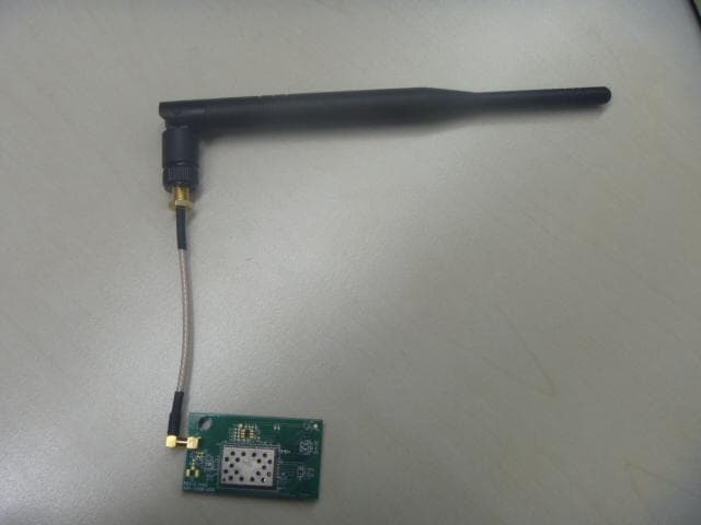
SU3RMWIFI
Apr 02, 2015RAE WIFI Module
Equipment Class
DTS - Digital Transmission System