T2DG12022.4 GHz Wireless Transmitter
Vson Technology Co.,Ltd.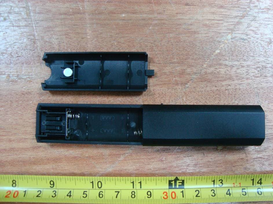
Click to zoom
Application Details
- Equipment Class
- DXX - Part 15 Low Power Communication Device Transmitter
- Date of Grant
- Mar 01, 2011
- Application Purpose
- Original Equipment
- Date of Application
- Mar 01, 2011
- Equipment Note
- 2.4 GHz Wireless Transmitter
- Frequency Range
- 2432.00000000 - 2432.00000000
- Company
- Vson Technology Co.,Ltd.
- Country
- China
Documents & Files
Document Text
Text extracted from the exhibit documents filed with the FCC. Open a document above to read the original.
Users Manual
Integrative Laser Presenter User's Manual Be sure to carefully read this user manual first for the proper use of the Integrative Mini Presenter and keep it for future reference. 1 Instruction It is a great tool for PowerPoint presentations! With it, you don't need to stand beside your computer or have an additional person click the slide for you! It contains two parts: transmitter and USB receiver. Features: 1. Easy carry The transmitter and receiver are integrated into one unit to easy carry! 2. Easily control the pace of your presentation Advanced radio frequency (RF) technology that works through walls and control distance is 10-meters / 32-feet away, so you never need to stand at beside of your computer. 3. Multifunctional presenter It combines the functions of laser pointer and slide changed. 4. Easy to use It is USB plug-and-play. No driver required. Just plug the receiver into the USB port on a PC and it works within seconds. I. Operation System Windows 2000 and above, Windows XP, Vista, Win 7 Laser hole Laser Page up Page down Power on Power off Receiver Battery cover O N O F F 2 II. Functions: Power switch, Power on or Power off. Page Up Page Down Laser Pointer Note: 2. Power switch function to save power when product is not used. III . Battery installation ● The product is powered by 2x AAA battery. ● Push and remove the battery cover. ● Insert 2x AAA battery into the battery holder. ● Put the battery cover back into position. 1.“PageUp”, “PageDown” and “Laser Pointer” three buttons adopt touch sensitive technology, just touch the button to realize the function. 3 Note 1. Do not insert battery into the device in the wrong direction. 2. Do not leave bad or exhausted battery in the device 3. If you do not use the device for a long period of time, remove the battery to avoid possible damage from battery corrosion. 4. If the device does not function correctly or if the operating range becomes reduced, try to replace the battery with new one. IV . Operating Hints For optimal performance and RF reception place the receiver at least 15cm away from all electrical devices, such as your monitor, speakers or external storage devices. Please make sure your fingers don't contact the touch key when turning on the power switch, otherwise, the touch key may not work. Please keep waiting in case of improper operation, the function will resume automatically around 10 seconds. It is normal phenomenon that if hold down the laser button for 5 seconds, the laser will become brighter. (for green laser presenter only) The laser button can't keep working above 20 seconds, which may cause the product damaged. (for green laser presenter only) It's normal phenomenon if no laser or weak laser under low temperature, please reuse after preheating. (for green laser presenter only) 4 V . Technical parameters Transmitter RF Frequency 2.4GRF Control distance 10 meters Laser Green or red laser Max output <1mW or <5mW Laser distance Up to 200M Working temperature 0~45 for red laser;°C 10~45 for green laser°C Battery 2 x AAA Working voltage 2.4~3.0V Sleep current <50uA Dimension 140.5x25.8x15.8MM Weight 64.1g for green laser; for red laser (Include receiver) Receiver Operation system Windows 2000 and above, Windows XP, Vista, Win 7 Interface USB1.1 , Compatible with USB2.0 Working voltage USB electricity supply (4.5~5.5V) Dimension 20.3x14.5x7.3MM Weight 1.9g VI Safety Measures Keep the presenter away from children. To avoid possible eye damage, never point the presenter at people especially their faces, or look directly into the presenter's laser beam. Avoid pointing the presenter's laser beam at a mirror or other highly reflective surface. 5 such as a microscope or binoculars. Any attempt to disassemble, adjust or repair the presenter may result in exposure to laser light or other safety hazards. NOTE The product adopts advance RF technology, the USB receiver will identify the first transmitter which is used. If you want to use different transmitters with the same receiver, please pull off the receiver and plug it again, after 6 seconds, press any key of the transmitter you want to use. Then it can work successfully. Never view the presenter's laser beam using telescopic devices, ! Any Changes or modifications not expressly approved by the party responsible for compliance could void the user's authority to operate the equipment. This device complies with part 15 of the FCC Rules. Operation is subject to the following two conditions: (1) This device may not cause harmful interference, and (2) this device must accept any interference received, including interference that may cause undesired operation. Note: This equipment has been tested and found to comply with the limits for a Class B digital device, pursuant to part 15 of the FCC Rules. These limits are designed to provide reasonable protection against harmful interference in a residential installation. Warning ! This equipment generates uses and can radiate radio frequency energy and, if not installed and used in accordance with the instructions, may cause harmful interference to radio communications. However, there is no guarantee that interference will not occur in a particular installation. If this equipment does cause harmful interference to radio or television reception, which can be determined by turning the equipment off and on, the user is encouraged to try to correct the interference by one or more of the following measures: —Reorient or relocate the receiving antenna. —Increase the separation between the equipment and receiver. —Connect the equipment into an outlet on a circuit different from that to which the receiver is connected. —Consult the dealer or an experienced radio/TV technician for help.
Cover Letter(s)
Add. 5 Floor, A building, Weixinda Xichen Industrial Park, Baoan District, 2122011 VSON TECHNOLOGY CO.,LTD. FCC Confidential Authorization Date: -- FEDERAL COMMUNICATIONS COMMISSIONS Authorization and Evaluation Division 7435 Oakland Mills Road Columbia, MD 21046 Confidentiality Request regarding application for certification of FCC ID: Pursuant to Sections 0.457 and 0.459 of the Commission’s Rules, we hereby request confidential treatment of information accompanying this application as outlined below: • Detailed Circuit Schematics of EUT--- (Long term) Block Diagram--- (Long term) Circuit Description--- (Long term) The above materials contain trade secrets and proprietary information not customarily released to the public. The public disclosure of these materials may be harmful to the applicant and provide unjustified benefits to its competitors. The applicant understands that pursuant to Section 0.457 of the Rules, disclosure of this application and all accompanying documentation will not be made before the date of the Grant for this application. Sincerely Yours, Signature: Typed or Printed Name: IVY WONG Title: Sales Manager Company Name: Vson Technology Co., Ltd. T2DG1202 5 Floor, A Building, Weixinda Xichen Industrial Park, Baoan District, Shenzhen 518102, China
External Photos
EXHIBIT B - EUT EXTERNAL PHOTOGRAPHS EUT – Front View EUT – Rear View EUT – Battery Off View
ID Label/Location Info
EXHIBIT A - FCC ID LABELING AND LOCATION FCC ID Label FCC ID Label Location The label shown shall be permanently affixed at a conspicuous location on the device and be readily visible to the user at the time purchase (Labeling requirements per 2.925) Label here
Internal Photos
EXHIBIT C - EUT INTERNAL PHOTOGRAPHS EUT – Cover off View EUT – Main Board Top View Antenna EUT –Main Board Bottom View EUT –Button Board Top View EUT – Button Board Bottom View EUT – Laser Transmitter Board Top View EUT – Laser Transmitter Board Bottom View
Test Report
Note: This test report is prepared for the customer shown above and for the device described herein. It may not be duplicated or used in part without prior written consent from Bay Area Compliance Laboratories Corp. (Shenzhen). This report must not be used by the customer to claim product certification, approval, or endorsement by NVLAP*, NIST, or any agency of the Federal Government. * This report contains data that are not covered by the NVLAP accreditation and are marked with an asterisk “★” (Rev.2) FCC PART 15.249 MEASUREMENT AND TEST REPORT For Vson Technology Co., Ltd. 5 Floor, A Building, Weixinda Xichen Industrial Park, Baoan District, Shenzhen, Guangdong 518102, China FCC ID: T2DG1202 Report Type: Original Report Product Type: 2.4 GHz Wireless Transmitter Test Engineer: Leon Chen Report Number: RSZ11021702 Report Date: 2011-02-28 Reviewed By: Merry Zhao EMC Engineer Prepared By: Bay Area Compliance Laboratories Corp. (Shenzhen) 6/F, the 3rd Phase of WanLi Industrial Building, ShiHua Road, FuTian Free Trade Zone Shenzhen, Guangdong, China Tel: +86-755-33320018 Fax: +86-755-33320008 Vson Technology Co., Ltd. FCC ID: T2DG1202 Report No.: RSZ11021702 Page 2 of 13 FCC Part15.249 Test Report TABLE OF CONTENTS GENERAL INFORMATION.......................................................................................................................................3 PRODUCT DESCRIPTION FOR EQUIPMENT UNDER TEST (EUT) .....................................................................................3 OBJECTIVE...................................................................................................................................................................3 RELATED SUBMITTAL(S)/GRANT(S).............................................................................................................................3 TEST METHODOLOGY..................................................................................................................................................3 TEST FACILITY.............................................................................................................................................................3 SYSTEM TEST CONFIGURATION ..........................................................................................................................5 JUSTIFICATION.............................................................................................................................................................5 EQUIPMENT MODIFICATIONS.......................................................................................................................................5 EXTERNAL I/O CABLE..................................................................................................................................................5 CONFIGURATION OF TEST SETUP.................................................................................................................................5 BLOCK DIAGRAM OF TEST SETUP................................................................................................................................5 SUMMARY OF TEST RESULTS ...............................................................................................................................6 FCC§15.203 - ANTENNA REQUIREMENT..............................................................................................................7 APPLICABLE STANDARD..............................................................................................................................................7 ANTENNA CONNECTOR CONSTRUCTION......................................................................................................................7 FCC§15.205(A), §15.209(A) & §15.249 - RADIATED EMISSIONS ........................................................................8 APPLICABLE STANDARD..............................................................................................................................................8 MEASUREMENT UNCERTAINTY....................................................................................................................................8 TEST EQUIPMENT SETUP..............................................................................................................................................8 EUT SETUP..................................................................................................................................................................9 TEST PROCEDURE........................................................................................................................................................9 CORRECTED AMPLITUDE & MARGIN CALCULATION...................................................................................................9 TEST EQUIPMENT LIST AND DETAILS.........................................................................................................................10 TEST DATA................................................................................................................................................................10 TEST RESULTS SUMMARY..........................................................................................................................................10 FCC§15.249(D) – OUT OF BAND EMISSIONS ......................................................................................................12 APPLICABLE STANDARD............................................................................................................................................12 TEST PROCEDURE......................................................................................................................................................12 MEASUREMENT UNCERTAINTY..................................................................................................................................12 TEST EQUIPMENT SETUP..…
Text truncated - open the document above for the full version.
Test Setup Photos
EXHIBIT D - TEST SETUP PHOTOGRAPHS Below 1 GHz: Spurious Radiated Emissions - Front View (Transmitting mode) Below 1 GHz: Spurious Radiated Emissions - Rear View (Transmitting mode) Above 1 GHz: Spurious Radiated Emissions - Front View Above 1 GHz: Spurious Radiated Emissions - Rear View
Contact Information
Applicant
Ivy Wong(Sales manager)
Test Firm
Bay Area Compliance Laboratory Corp. (Shenzhen)John Chan
Technical Specifications
| # | Rule Parts | Frequency Range | Power Output |
|---|---|---|---|
| 1 | 15C | 2.43 GHz - 2.43 GHz | - |
Other Applications from Vson Technology Co.,Ltd.
T2DV832
Sep 05, 2013Wireless Presenter
Equipment Class
DXX - Part 15 Low Power Communication Device Transmitter
T2DV215
Dec 26, 2012Wireless Presenter
Equipment Class
DXX - Part 15 Low Power Communication Device Transmitter
T2DV829
Jan 19, 2012Wireless Presenter
Equipment Class
DXX - Part 15 Low Power Communication Device Transmitter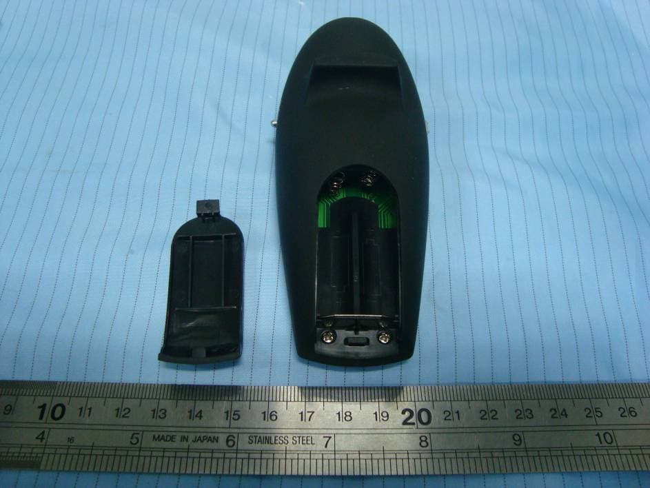
T2DV820515
Mar 21, 2011Wireless Presenter
Equipment Class
DXX - Part 15 Low Power Communication Device Transmitter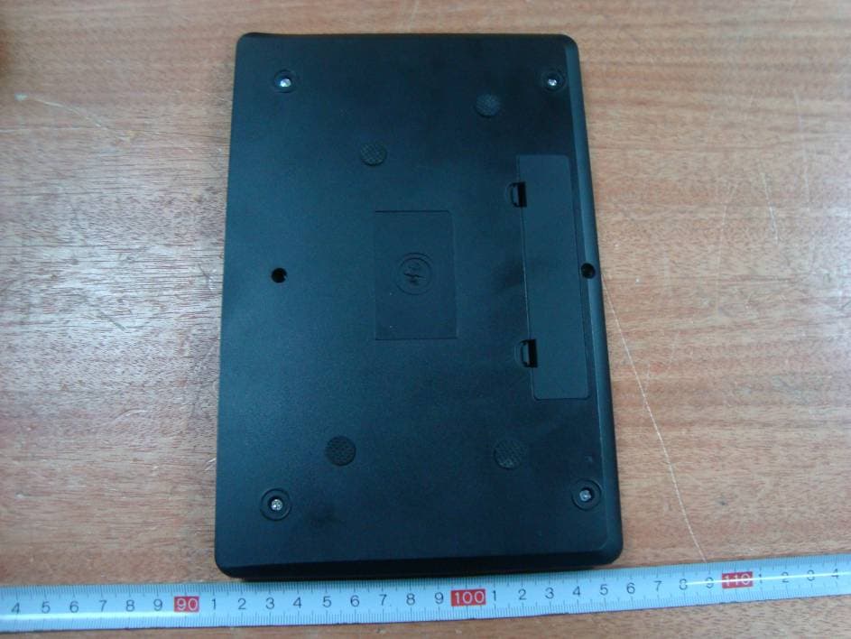
T2DTT1100
Oct 30, 20102.4 GHz Wireless Transmitter
Equipment Class
DXX - Part 15 Low Power Communication Device Transmitter