T2DTT11002.4 GHz Wireless Transmitter
Vson Technology Co.,Ltd.
Click to zoom
Application Details
- Equipment Class
- DXX - Part 15 Low Power Communication Device Transmitter
- Date of Grant
- Oct 30, 2010
- Application Purpose
- Original Equipment
- Date of Application
- Oct 30, 2010
- Equipment Note
- 2.4 GHz Wireless Transmitter
- Frequency Range
- 2417.00000000 - 2468.00000000
- Company
- Vson Technology Co.,Ltd.
- Country
- China
Documents & Files
Document Text
Text extracted from the exhibit documents filed with the FCC. Open a document above to read the original.
Users Manual
Mini Electronic White Board User’s manual Be sure to carefully read this user’s manual first for the proper use of the Mini electronic board presenter and keep it for future reference. 1 Tables of contents Features··························································································· 2 I. Operation system ·········································································· 2 II. Part description ············································································ 3 III. Installation ··················································································· 5 IV. Operation manual ······································································· 5 V. Battery installation ······································································· 9 VI. Technology parameter ······························································ 10 VII. Attention ·················································································· 11 2 Features: z The system consists of a mini white board remote, a touchpen, a receiver and a program. z Combining state of the art 2.4GHz radio frequency technology, control distance up to 8m, an ideal partner for the projector and the PC. z Up to date electromagnetism technology, orientation precisely by 4 calibration points. Please be sure to set them before using. z The Touch pen is built-in the mini white board, easy to carry. z Multicolor handwritings are available. z Effective tablet area up to 14cm×7.8cm. z Remark and label on the screen can be saved; the operation steps can be record. z The white board is also a touchscreen. Touch and control the mouse pointer by the Touch pen. z Replace the mouse or coexist with the mouse. z Short response time, computer response to Tablet operations synchronously. z Shortcut keys for your easy working. z Rechargeable batteries are convenient for use. I. Operation system WindowsXP, Win 7 II. Parts description 3 Mini white board front view USB receiver KEY FUNCTION Shortcut key Desktop +D Colorized pen/Screen mode OK Enter Enter Touch pen LED 4 UP arrow /Red pen Left arrow/Black pen Right arrow/Blue pen Down arrow/Green pen L Mouse left button R Mouse right button/Open brush pencil/eraser/magnifier/focus lamp menu bar Pre. Page/Line weight thicker/ Enlarge eraser size /magnification /focus lamp size Page Up Next page/Line weight thinner/ Diminish eraser size/magnification /focus lamp size Page Down Clear handwriting Close current window Alt+F4 Alt+Tab Switch current windows Alt+Tab ESC Esc Esc III.Installation 1. install the program Take the installation CD out from the product package and insert it into the CD-ROM. Open the CD and double click the “TopA White 5 Board mini_setup_V1.1.0.exe” to start installation. Complete the installation, and view the icon of the program on the desktop. 2. Install the receiver Plug the USB receiver to the available USB port. And the Program will find the new hardware and pop-up the Add Hardware Wizard dialog box. Follow the wizard, find the driver, and finish the installation. After the connection, move the mouse pointer to the icon of the Mini Electronic White Board, the program will present “ ”. NOTE!! ① The driver is at the folder which you have installed the program to. ② The detailed operations refer to the installation guide(”TopA White Board mini_Installation guide_V1.1.0.doc”). IV. Operation manual 1. Start mini board system Please refer to the installation guide. 2. Screen Calibration User have to set the touchpad before use it. To open short-cut Menu, please click right mouse button on the mini electronic white board icon on the task bar in the lower screen. And select “Screen Calibration”. Click the coordinate by touch pen point by point to calibrate coordinate from the PC to the mini white board. 6 3. Remote control The touch control screen is absolutely convenient to do any interactive operations, and operate the applications on PC using the touch pen. 4. Switch mode Press and hold the “” button on the mini white board, user can remark or label on the white board via the touch pen by pressing the “L” key and move the touch pen. Real-time data will be transmitted to and displayed on the computer screen. Press and hold the “ ” button again, will switch into the screen mode, at this moment, user could run other applications and move the mouse pointer on desktop. Note! When you press the “ ” button, don’t touch the mini white board touch screen with the touch pen or other objects. 5. Clear Press “” button on the white board to clear the text we write on the PC screen. As well as, you can press “E” button on the keyboard to clear the handwritten on the touch screen. 6. Mouse right/left key Press the “R” or “L” key on the white board, just like clicking the mouse right or left key. 7 As well as ,when you use the brush pencil, or eraser, or magnifier or focus lamp, press the “R” button, you can open corresponding menu bar to set up some parameters. At the same time press the “L”button and move the touch pen, user could draw lines, erase handwritten with the eraser, move the magnifier or focus lamp in corresponding function mode. 7. Shortcut keys ① Press “” key, show desktop. ② Press “ ” key, just like press the “Enter ”button on the keyboard. ③ The “ ” , “”, “”, “” keys, equivalent to the four directions arrows. But, when you use the brush pencil, you can respectively press the four direction buttons to change pen’s color. Press “ ”button is on behalf of opening the red pen. Press “ ”button is on behalf of opening the green pen. Press “ ”button is on behalf of opening the black pen. Press “ ”button is on behalf of opening the blue pen. ④ Press “ ” or “”, work as page up or page down on the keyboard. However, when you use the brush pencil, or eraser, or magnifier or focus lamp, press the “ ”button, you could make the line weight thicker, or enlarge the eraser size, magnification or focus lamp size. And press the “ ”button, you could…
Text truncated - open the document above for the full version.
Cover Letter(s)
Vson Technology Co., Ltd.. 5 Floor, A Building, Weixinda Xichen Industrial Park, Baoan District, Shenzhen, 518102, China FCC Confidential Authorization Date: 2010-10-18 FEDERAL COMMUNICATIONS COMMISSIONS Authorization and Evaluation Division 7435 Oakland Mills Road Columbia, MD 21046 Confidentiality Request regarding application for certification of FCC ID: T2DTT1100 Pursuant to Sections 0.457 and 0.459 of the Commission’s Rules, we hereby request confidential treatment of information accompanying this application as outlined below: • Detailed Circuit Schematics of EUT--- (Long term) Block Diagram--- (Long term) Circuit Description--- (Long term) The above materials contain trade secrets and proprietary information not customarily released to the public. The public disclosure of these materials may be harmful to the applicant and provide unjustified benefits to its competitors. The applicant understands that pursuant to Section 0.457 of the Rules, disclosure of this application and all accompanying documentation will not be made before the date of the Grant for this application. Sincerely Yours, Signature: Typed or Printed Name: IVY WONG Title: Sales Manager Company Name: Vson Technology Co., Ltd.
External Photos
EXHIBIT B - EUT EXTERNAL PHOTOGRAPHS EUT – Front View EUT – Rear View EUT – Battery Off View
ID Label/Location Info
EXHIBIT A - FCC ID LABELING AND LOCATION FCC ID Label FCC ID Label Location The label shown shall be permanently affixed at a conspicuous location on the device and be readily visible to the user at the time purchase (Labeling requirements per 2.925) FCC ID: T2DTT1100 Model: TT1100 This device complies with part 15 of the FCC Rules. Operation is subject to the following two conditions: (1) This device may not cause harmful interference, and (2) This device must accept any interference received, including interference that may cause undesired operation. Vson Technology Co., Ltd.
Internal Photos
EXHIBIT C - EUT INTERNAL PHOTOGRAPHS EUT – Cover off View EUT – Main Board Top View Antenna EUT – Main Board Bottom View
Test Report
Note: This test report is prepared for the customer shown above and for the device described herein. It may not be duplicated or used in part without prior written consent from Bay Area Compliance Laboratories Corp. (Shenzhen). This report must not be used by the customer to claim product certification, approval, or endorsement by NVLAP*, NIST, or any agency of the Federal Government. * This report may contain data that are not covered by the NVLAP accreditation and are marked with an asterisk “*” (Rev.2) FCC PART 15.249 MEASUREMENT AND TEST REPORT For Vson Technology Co., Ltd. 5 Floor, A Building, Weixinda Xichen Industrial Park, Baoan District, Shenzhen, Guangdong 518102, China FCC ID: T2DTT1100 Report Type: Original Report Product Type: 2.4 GHz Wireless Transmitter Test Engineer: Leon Chen Report Number: RSZ10092801 Report Date: 2010-10-26 Reviewed By: Merry Zhao EMC Engineer Prepared By: Bay Area Compliance Laboratories Corp. (Shenzhen) 6/F, the 3rd Phase of WanLi Industrial Building, ShiHua Road, FuTian Free Trade Zone Shenzhen, Guangdong, China Tel: +86-755-33320018 Fax: +86-755-33320008 Vson Technology Co., Ltd. FCC ID: T2DTT1100 Report No.: RSZ10092801 Page 2 of 23 FCC Part15.249 Test Report TABLE OF CONTENTS GENERAL INFORMATION.......................................................................................................................................4 PRODUCT DESCRIPTION FOR EQUIPMENT UNDER TEST (EUT) .....................................................................................4 OBJECTIVE...................................................................................................................................................................4 RELATED SUBMITTAL(S)/GRANT(S).............................................................................................................................4 TEST METHODOLOGY..................................................................................................................................................4 TEST FACILITY.............................................................................................................................................................4 SYSTEM TEST CONFIGURATION ..........................................................................................................................6 JUSTIFICATION.............................................................................................................................................................6 EQUIPMENT MODIFICATIONS.......................................................................................................................................6 HOST SYSTEM CONFIGURATION LIST AND DETAILS....................................................................................................6 LOCAL SUPPORT EQUIPMENT LIST AND DETAILS........................................................................................................6 EXTERNAL I/O CABLE..................................................................................................................................................6 CONFIGURATION OF TEST SETUP.................................................................................................................................7 BLOCK DIAGRAM OF TEST SETUP................................................................................................................................7 SUMMARY OF TEST RESULTS ...............................................................................................................................8 FCC §15.203 - ANTENNA REQUIREMENT.............................................................................................................9 APPLICABLE STANDARD..............................................................................................................................................9 ANTENNA CONNECTOR CONSTRUCTION......................................................................................................................9 FCC §15.207 (A) – AC LINE CONDUCTED EMISSIONS ....................................................................................10 APPLICABLE STANDARD............................................................................................................................................10 MEASUREMENT UNCERTAINTY..................................................................................................................................10 EUT SETUP................................................................................................................................................................10 EMI TEST RECEIVER SETUP.......................................................................................................................................11 TEST EQUIPMENT LIST AND DETAILS.........................................................................................................................11 TEST PROCEDURE......................................................................................................................................................11 TEST RESULTS SUMMARY..........................................................................................................................................11 TEST DATA................................................................................................................................................................11 FCC §15.205(A), §15.209(A) & §15.249 - RADIATED EMISSIONS .....................................................................14 APPLICABLE STANDARD............................................................................................................................................14 MEASUREMENT UNCERTAINTY..................................................................................................................................14 TEST EQUIPMENT SETUP.................................…
Text truncated - open the document above for the full version.
Test Setup Photos
EXHIBIT D - TEST SETUP PHOTOGRAPHS Conducted Emissions - Front View Conducted Emissions - Side View Below 1GHz: Spurious Radiated Emissions - Front View (Transmitting mode) Below 1GHz: Spurious Radiated Emissions - Rear View (Transmitting mode) Above 1GHz: Spurious Radiated Emissions - Front View Above 1GHz: Spurious Radiated Emissions - Rear View
Contact Information
Applicant
Ivy Wong(Sales manager)
Test Firm
Bay Area Compliance Laboratory Corp. (Shenzhen)John Chan
Technical Specifications
| # | Rule Parts | Frequency Range | Power Output |
|---|---|---|---|
| 1 | 15C | 2.42 GHz - 2.47 GHz | - |
Other Applications from Vson Technology Co.,Ltd.
T2DV832
Sep 05, 2013Wireless Presenter
Equipment Class
DXX - Part 15 Low Power Communication Device Transmitter
T2DV215
Dec 26, 2012Wireless Presenter
Equipment Class
DXX - Part 15 Low Power Communication Device Transmitter
T2DV829
Jan 19, 2012Wireless Presenter
Equipment Class
DXX - Part 15 Low Power Communication Device Transmitter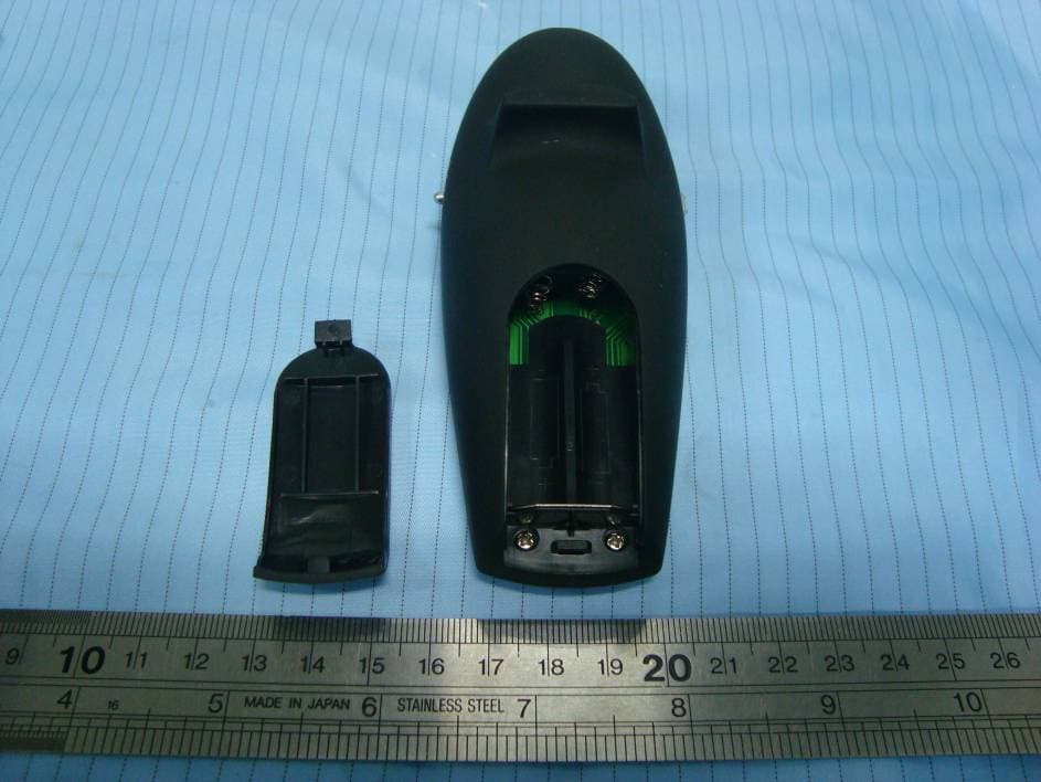
T2DV820515
Mar 21, 2011Wireless Presenter
Equipment Class
DXX - Part 15 Low Power Communication Device Transmitter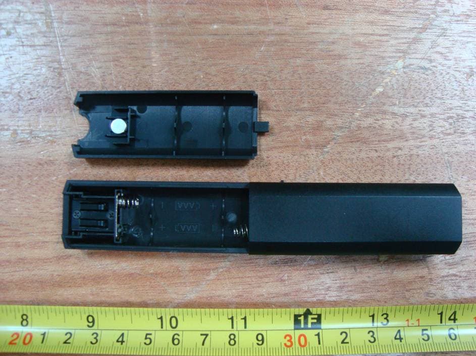
T2DG1202
Mar 01, 20112.4 GHz Wireless Transmitter
Equipment Class
DXX - Part 15 Low Power Communication Device Transmitter