T35ANIMALCALLERAttractor Remote Digital Caller
Hunter�s Specialties, Inc.
Click to zoom
Application Details
- Equipment Class
- DSR - Part 15 Remote Control/Security Device Transceiver
- Date of Grant
- Mar 27, 2006
- Application Purpose
- Original Equipment
- Date of Application
- Mar 27, 2006
- Equipment Note
- Attractor Remote Digital Caller
- Frequency Range
- 315.00000000 - 315.00000000
- Company
- Hunter�s Specialties, Inc.
- Country
- United States
Documents & Files
Document Text
Text extracted from the exhibit documents filed with the FCC. Open a document above to read the original.
Users Manual
1 Johnny Stewart Wildlife Calls Attractor Remote Digital Caller Operating Instructions Attractor Remote Digital Caller Your new Attractor Remote Digital Caller is backed by 40 years of experience. The Attractor will create incredible fun and suc cess for your enjoyment of the outdoors. Whether used for hunting, photography or observation of wildlife, the Attractor will creat e opportunities for you to experience nature up close in a dynamic way with Superior Sounds...Dynamic Results . Attractor Features: 1. Authentic Johnny Stewart Live Animal Recordings, Digitally Re-mastered. 2. Remote control operation up to 50 yards. 3. 13 ounces total weight. 4. 5 digital call sounds and 1 stop button. 5. Continuous play. 6. 15 second sound loops. 7. 90 decibels* at full power. 8. Weather resistant sturdy construction. 9. Weather-guard molded seams. 10. Water-resistant speaker cover. 11. ON/OFF Volume Control Switch on Base Unit. 12. Green LED light power indicator. 13. Non-slip push button pads on Transmitter. 14. Remote transmitter holder. 15. Heavy duty nylon lanyard. 16. 4 AA and 1 12 volt batteries included. 17. Note* : Combining Attractor Remote Digital Caller with Power Pro Convert-A-Caller (PPC-1) will significantly increase volume from 90 decibels (db) to 120 db. POWER SOURCE The Attractor is powered by four AA batteries in Base Unit and a single 12 Volt battery in the Transmitter (batteries included) . No need to fumble with screws on Base Unit to change 4 AA batteries. When powered on, the Green LED light will glow on speaker. Maximum performance is provided by alkaline batteries. Note: Th e Attractor will NOT shut down due to inactivity and remains powered until Base Unit is manually shut off. 2 CALLING OPERATIONS To begin calling with the Attractor, turn on volume control switc h, indicated by Green LED light on speaker. Begin calling by pressing the button on transmitter located next to the desired sound. Selected sound will play continually until stop button i s depressed on transmitter. To change sounds while calling, depr ess desired sound button on transmitter. Increase/decrease volu me by rotating the volume control switch on Base Unit only. Note: Combining Attractor Remote Digital Caller with Power Pro Convert-A-Caller (PPC-1) will significantly increase volume from 90 decibels (db) to 120 db. BELT LOOPS/LANYARDS The belt loop on the back of the Attractor Base Unit and Tran smitter can be removed with Philips screw driver. Using the lanya rd to hang Base Unit from limb or bush will increase remote range beyond 50 yards, depending on conditions. Attaching lanyard to transmitter to wear around neck eases operation and helps prevent loss/damage. STORAGE For proper storage ensure that the Attractor is turned off. If you intend to store your Attractor for an extended period, the AA batteries should be removed from the Base Unit. MAINTENANCE With proper care your Attractor requires little or no maintenance. Always carry a set of new batteries in your vehicle. The 12 volt, 23 amp battery in Transmitter can be purchased at most Battery or Hardware Stores. ATTRACTOR WARRANTY Your Johnny Stewart Attractor Di gital Caller is a quality product , fully warranted against defect s in materials or workmanship for a period of 90 days from the date of purchase. Faul ty parts covered under this warranty will be replaced free of charge. If it becomes n ecessary to return your unit, all shipments must be insured and prepaid to a nd from the factory. This warran ty is void if the warranty card has not been returned to us at the time of purchase. This warranty shall not apply if the unit has not been operated in accordance with the instruction or the machine has been alte red, repaired, mistreated in any way that we believe has caused the failure or de struction of the unit. This warranty is in lieu of all other expressed or implied except for any special written agreement entered into with Johnny Stewart. Important Notices & Return Policy If you experience difficulty or ha ve any questions please call: Hunter Specialties, Inc./Johnny Stew art Wildlife Calls at 1-319-395-0321 Please fill out and return the warranty card provided. Serial Number is located inside AA battery compartment on Base Unit. 3 FCC Warning: Changes or modifications to this unit not expressly approved by the party responsible for compliance will void the user’s authority to operate the equipment. Any change to the equipment will void FCC grant. This equipment has been tested and found to comply with the limits for a Class B digital device, pursuant to part 15 of the FCC Rules. These limits are designed to provide reasonable protection against harmful interference in a residential installation. This equipment generates, uses and can radiate radio frequency energy and, if not installed and used in accordance with the instructions, may cause harmful interference to radio communications. However, there is no guarantee that interference will not occur in a particular installation. If this equipment does cause harmful interference to radio or television reception, which can be determined by turning the equipment off and on, the user is encouraged to try to correct the interference by one or more of the following measures: --Reorient or relocate the receiving antenna (base unit). --Increase the separation between the equipment and receiver. --Consult the dealer or an experienced radio/TV technician for help. This device complies with part 15 of the FCC Rules. Operation is subject to the following two conditions: (1) This device may not cause harmful interference, and (2) this device must accept any interference received, including interference that may cause undesired operation. The Attractor is in compliance with FCC radiation exposure limits set forth for uncontrolled environments.
Block Diagram
1 2 34 ABCD 4 3 2 1 D CBA Title Number Revision Size A4 Date: 14-Feb-2006 Sheet of File: D:\project\HUNTER\GAME CALL\pcb\BLOCK.Ddb Drawn By: operato circuit cpu encoder modulator transmiter amplifier Battery voltage ragulator Attractor remote block diagram Sangao Antenna ASK 315MHZ +/-75KHZ
External Photos
External Photos EUT Top View EUT Bottom View
ID Label/Location Info
ID Label Label FCC ID: T35ANIMALCALLER
ID Label/Location Info
ID Label/Location Label Location Information Specifications: Text is Black or white in color and is left justified. Labels are printed in indelible ink on permanent adhesive backing or silk-screened onto the EUT or shall be affixed at a conspicuous location on the EUT. Refer to the below arrow.
Internal Photos
Internal Photos EUT - Uncovered View EUT – PCB Top View EUT –PCB Bottom View
Operational Description
Attractor Remote Digital Caller circuit description Master circuit: Q1 is voltage regulator IC, supply the 3.3V voltage power to IC1 and U2. U2 is program MCU, when the RF receiver module have data output, the MCU will encode data and out high level to trigger IC1 play sounds, IC1 is voice IC , include five sounds and one reset input PIN. According to U2 output trigger signal perform different play sounds or reset. U3 is sounds power amplifier circuit. IC1 output sounds signal pass through U3 Power amplifier driver the speaker. Transmit module circuit: Q1 is power control, when any key press will provide power to U3 and Q2. U3 is encoder IC, The 18PIN is in series with Q1 C and terminal and get work power. U3 bring the address signal to high frequence tube Q2 and control it(1~7PIN of U3 contact The ground or VCC then can choose the address signal group.) A1(SAW1) is resonance component, can supply 315MHz frequence, after modulated and Amplified, transmit to around space though antenna. Transmit circuit working ASK mode.
Operational Description
Remoter module parameter: (TX) a. Working Voltage:DC 6--12V b. Communicate mode :unilateralism c. Data transmit rate :10KHZ d. Modulation mode :ASK e. Working current:≤10mA@12V f. Transmit power :8mw@12V g. Frequency : 315MHZ; h. Frequency flutter :±75KHz; i. Working temperature range:-10°C ~+60°C
Schematics
1 2 34 ABCD 4 3 2 1 D CBA Title Number Revision Size A4 Date: 14-Feb-2006 Sheet of File: D:\project\HUNTER\GAME CALL\schematic\ prodator schematic.Ddb Drawn By: R14680k 1 1 2 2 3 3 4 4 5 5 6 6 7 7 8 8 9 9 10 10 11 11 12 12 13 13 14 14 15 15 16 16 17 17 18 18 PT2262 IC1 1 1 2 2 R13M R410K R510K K1K1 K2 12V R1310K C22.2PC36.8P R11 273(NO USE) 3 1 2 JA1 R315M 12V Q2 2SC3356 C4100P LED1 R8392 R9103 Q1 8550 K4 K5 K3 R610K R210K R310K Attractor Remote Digital Caller Transmiter circuit C1102 R710K K6K6 R121.5K R10150 R?BATTERY 12V ICO-5502 Tx ASK 315MHZ+/-75KHZ
Test Report
Note: The test report is specially limited to the above company and this particular sample only. It may not be duplicated without prior written consent of Bay Area Compliance Lab Corp. (ShenZhen). This report must not be used by the client to claim product certification, approval, or endorsement by NVLAP, NIST or any agency of the US Government. FCC PART 15.231 EMI MEASUREMENT AND TEST REPORT For Hunter’s Specialties, Inc. 6000 Huntington Court N.E. Cedar Rapids, IA 52402 USA FCC ID: T35ANIMALCALLER March 14, 2006 This Report Concerns: Original Report Equipment Type: Attractor Remote Digital Caller Test Engineer: Louise Lu Tower Yan Report No.: RSZ06022302 Test Date: March 1-13, 2006 Reviewed By: Chris Zeng Prepared By: Bay Area Compliance Lab Corp. (ShenZhen) 6/F, the 3rd Phase of WanLi Industrial Building, ShiHua Road, FuTian Free Trade Zone, ShenZhen, Guangdong 518038, P.R.China Tel: +86-755-33320018 Fax: +86-755-33320008 Hunter’s Specialties, Inc. FCC ID: T35ANIMALCALLER Report # RSZ06022302 Page 2 of 17 FCC Part 15.231 Test Report TABLE OF CONTENTS GENERAL INFORMATION.......................................................................................................................................3 PRODUCT DESCRIPTION FOR EQUIPMENT UNDER TEST (EUT) ....................................................................................3 OBJECTIVE...................................................................................................................................................................3 RELATED SUBMITTAL(S)/GRANT(S).............................................................................................................................3 TEST METHODOLOGY..................................................................................................................................................3 TEST FACILITY.............................................................................................................................................................3 SYSTEM TEST CONFIGURATION ..........................................................................................................................4 JUSTIFICATION.............................................................................................................................................................4 EUT EXERCISE SOFTWARE..........................................................................................................................................4 SPECIAL ACCESSORIES.................................................................................................................................................4 EQUIPMENT MODIFICATIONS.......................................................................................................................................4 CONFIGURATION OF TEST SETUP.................................................................................................................................5 BLOCK DIAGRAM OF TEST SETUP................................................................................................................................5 SUMMARY OF TEST RESULTS...............................................................................................................................6 §15.203 - ANTENNA REQUIREMENT......................................................................................................................7 STANDARD APPLICABLE..............................................................................................................................................7 §15.205, §15.209, §15.231 (B)- RADIATED EMISSION...........................................................................................8 MEASUREMENT UNCERTAINTY....................................................................................................................................8 EUT SETUP..................................................................................................................................................................8 EMI TEST RECEIVER SETUP.........................................................................................................................................8 TEST EQUIPMENT LIST AND DETAILS...........................................................................................................................9 TEST PROCEDURE........................................................................................................................................................9 STANDARD APPLICABLE..............................................................................................................................................9 CORRECTED AMPLITUDE & MARGIN CALCULATION...................................................................................................9 TEST RESULTS SUMMARY..........................................................................................................................................10 TEST DATA................................................................................................................................................................11 PLOT(S) OF TEST DATA..............................................................................................................................................11 §15.231(C) 20DB BANDWIDTH TESTING .............................................................................................................14 REQUIREMENT...........................................................................................................................................................14 TEST EQUIPMENT LIST AND DETAILS.........................................................................................................................14 TEST PROCEDURE............................................................................................................................................…
Text truncated - open the document above for the full version.
Test Setup Photos
Test Setup Photos Radiated Emission - Front View (30-1000MHz) Radiated Emission - Rear View (30-1000MHz) Radiated Emission - Front View (Above 1GHz) Radiated Emission - Rear View (Above 1GHz) Radiated Emission - Side View
Contact Information
Applicant
David Mortensen(Director Of Product Development)
Test Firm
Bay Area Compliance Laboratory Corp. (Shenzhen)John Chan
Technical Specifications
| # | Rule Parts | Frequency Range | Power Output |
|---|---|---|---|
| 1 | 15.231 | 315 MHz - 315 MHz | - |
Other Applications from Hunter�s Specialties, Inc.
T35JS-4
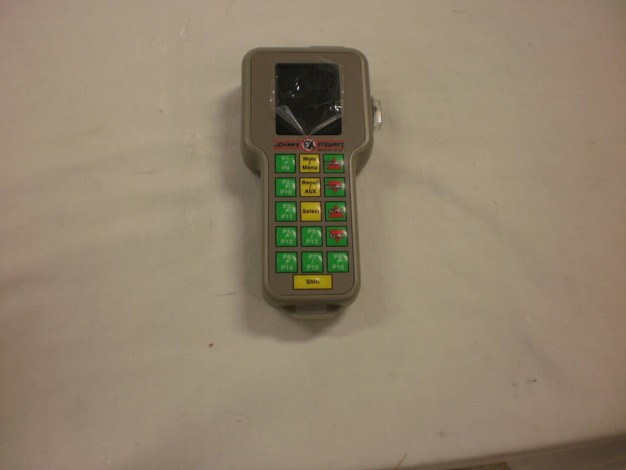
Jul 23, 2012DIGITAL GAME CALLER - EXECUTIONER
Equipment Class
DXX - Part 15 Low Power Communication Device Transmitter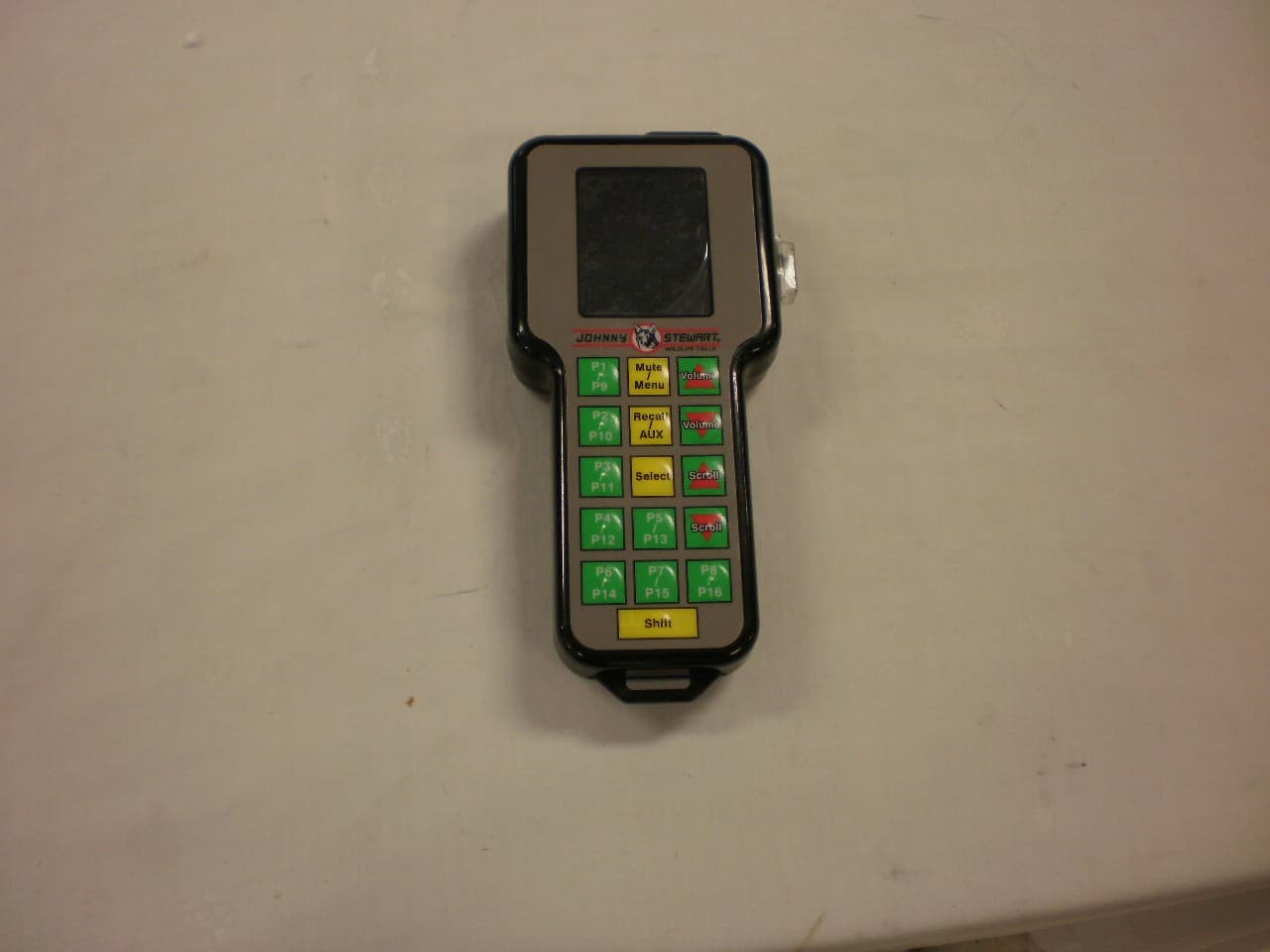
T35JS-3
Jul 23, 2012DIGITAL GAME CALLER - GALLOWS
Equipment Class
DXX - Part 15 Low Power Communication Device Transmitter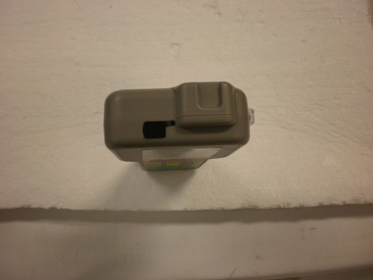
T35JS-2
Jul 17, 2012DIGITAL GAME CALLER-BLOODHOUND
Equipment Class
DXX - Part 15 Low Power Communication Device Transmitter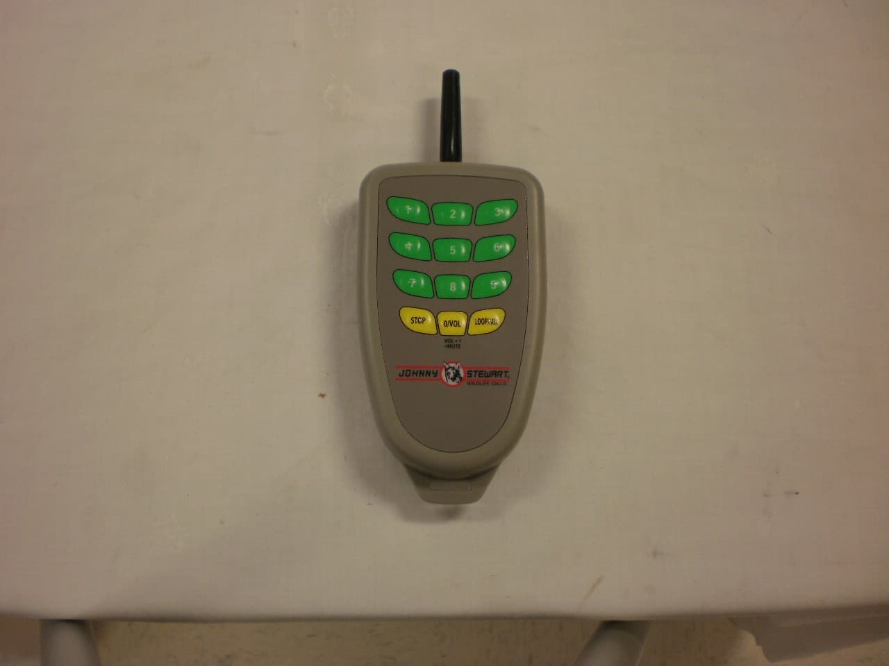
T35JS-1
Jul 12, 2012DIGITAL GAME CALLER-JURY-TRANSMITTER
Equipment Class
DXX - Part 15 Low Power Communication Device Transmitter
T35PM-4
Feb 05, 2007PM-4 Remote Digital Caller
Equipment Class
DSC - Part 15 Security/Remote Control Transmitter