T38PCD2003GSM Mobile Phone
Cellon Communications Technology (Shenzhen) Co.,Ltd.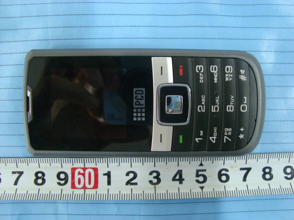
Click to zoom
Application Details
- Equipment Class
- PCE - PCS Licensed Transmitter held to ear
- Date of Grant
- May 27, 2010
- Application Purpose
- Original Equipment
- Date of Application
- May 27, 2010
- Equipment Note
- GSM Mobile Phone
- Frequency Range
- 1850.20000000 - 1909.80000000
- Country
- China
Documents & Files
Document Text
Text extracted from the exhibit documents filed with the FCC. Open a document above to read the original.
Users Manual
1 Introduction 1.1 Phone Display 2 We continuously strive to improve our products. Therefore, we reserve the rights to revise this user manual or withdraw it at any time without prior notice. 1.2 Key Key Function Pick-Up Press to answer a call or dial a call after you enter a phone number. In idle mode, press to view the call log. Hang-Up Press to end a call. Press and hold to turn the phone on/off. Within a menu, press to return to idle mode. Left Soft Key In idle mode, press to enter the Main menu. Press to access the option listed directly above it on the display. Right Soft Key In idle mode, press to access the Phonebook list. Press to access the option listed directly above it on the display. Within a menu, press to return to the previous screen. OK Key In idle mode, press to enter the Main menu Numeric key Press to enter the corresponding number, letter or symbol located on the key. Within a menu, press to access the corresponding menu option. 3 * Press the * Key twice quickly to enter ‘+’ to make an international call. Press and hold the * Key to toggle between *, +, (pause character) P, and (wait character) W. Press to enter symbol when editing text. # In idle mode, press and hold to activate or deactivate the silent mode. Press to switch input modes when entering text. Navigation Key Within a menu, press Up, Down, Left or Right to scroll through menu options. Note: “Press” in this manual, means to press and release the key; “press and hold” means to press and hold the key for at least 2 seconds. 1.3 Icons & Symbols Icon Description Network - The left portion indicates whether your phone is already registered with a network and the right portion indicates signal strength (from no signal to strongest). 4 Battery - Indicates battery level. When charging, a scrolling icon will be displayed. The more bars, the stronger the charge. To log on GPRS - The icon will be displayed only when you have logged onto GPRS. MMS - Indicates you have one or more unread MMS messages. Message - Indicates you have one or more unread messages. Push message-Indicates that you have received new push message. Voicemail- Indicates voice messages that have not been heard. Missed call - Indicates there is a missed call. Call Divert - Indicates that “Divert All Voice Calls” is activated. Alarm-Indicates that the alarm clock is on. Headset-Indicates that headset profile is activated. Alert type is “Ring”. 5 2 Getting Started Please read the safety instructions in the "Safety Information and Notices" section before use. 2.1 Inserting the SIM Card 2.1.1 Remove the back cover(1), remove the battery (2), and insert the SIM card (3) (2) (3) 2.1.2 Install the battery and back cover 6 2.2 Turning the phone on To turn the phone on, press and hold the Hang Up key. Enter the PIN code if required. 2.3 Charging the Battery 1. Ensure the battery is inserted in the handset. To charge the battery, plug in the charger connector at the bottom of your phone (USB interface) and then plug the other end into an AC power socket. 2. The battery symbol indicates the charging status. While charging, the charge indicators will scroll. When all the scroll bars are steady, the battery is fully charged. 3. Disconnect the charger from the phone. 4. Disconnect the charger from the AC power socket. 7 Note: If the battery is powerless, the battery icon will reappear after a few minutes of charging. a . Inserting a T-Flash Card 1. Lift up the T-Flash card cover on the right side of the SIM card slot. Pull the cover down if it is locked and then lift. A word “OPEN” will prompt you in the correct direction. 2. With the metal contacts facing down, gently slide the T-Flash card into the slot. 3. Press and pull the cover up to lock it. A word “Lock” will prompt you in the correct direction. b . Transfer files to the T-Flash card 1. Insert your T-Flash card into a card reader, and then connect the card reader to the USB port of a PC. The PC will auto detect the card reader as a removable disk. You can access the T-Flash card memory now. 2. Download or upload the files to T-Flash card. 3. When the transfer is finished, please make sure that you safely remove the card reader by clicking . 4. Finally, insert your T-Flash card into your cellular phone, you can view the files in Multimedia > File Manager > Memory Card. 8 c . Important Password Phone lock password is 1122. 9 3 Text Entry 3.1 Input Method During text editing, you can press the # Key to switch input modes or press the Left Soft Key [Option] and select Input Method to select different input modes. 3.1.1 Entering Symbols In any input mode, press the * Key to open the symbols input screen. 3.2 Smart Input Method 2 to 9 Press to input letters 1 Press to input symbol 0 Press to input space ◀ / ▶ Press to confirm the letter or word, or move the cursor to left or right. ▲ / ▼ Press to browse the last or next available word. Left Soft Key (Select) or the OK Key Press to confirm the letter or word Right Soft Key (Clear) Press to clear a letter, press and hold to clear all entries 10 # Switch between input mode * Press to activate punctuation mode Example: How to enter the word "HOME" 1. Press the # Key to switch to ABC ; 2. Press 4 6 6 3, the first word “GOOD” appears; 3. Press ▶ to browse and select “HOME”; 4. Press the Left Soft Key [Select] or OK Key to confirm “HOME”. 3.3 Multi-tap Input Using this mode requires you to press a key as many times as needed to enter the desired letter. To enter the word «home» in Multi-tap input mode “ abc”, press key 4(G H I), 4 (G H I), 6(MN O ), 6(MN O ), 6(MN O ), 6 ( M NO), 3(D E F), 3 (D E F). 3.4 Numeric Input Press the # Key to select " 123" then you can enter the numbers. 11 4 Calling 4.1 Making a Call Note: You can make a call only when the network name appears on the screen. 1. In idle mode,enter the phone number. 2. Press the Pick-Up Key to dial the number. 3. Press the Hang-Up Key to end the call. Note: During a call, press the Navigation Key Up/Down to…
Text truncated - open the document above for the full version.
External Photos
EXHIBIT B - EUT EXTERNAL PHOTOGRAPHS EUT – Front View EUT – Rear View
ID Label/Location Info
EXHIBIT A - FCC ID LABELING AND LOCATION FCC ID Label Model: C2003 Model: GLPL138 Model: GLPL138PA FCC ID Label Location The label shown shall be permanently affixed at a conspicuous location on the device and be readily visible to the user at the time purchase (Labeling requirements per 2.925) Label here
Internal Photos
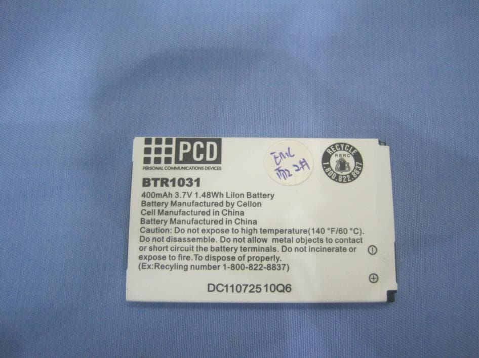
EXHIBIT C - EUT INTERNAL PHOTOGRAPHS EUT –Battery Removed View 1 EUT –Battery Removed View 2 Antenna EUT – Front Cover off View EUT – Rear Cover off View EUT – LCD Top View EUT – LCD Bottom View EUT – Main Board Top View EUT – Main Board without Shielded Cover Top View EUT – Main Board Bottom View EUT – Main Board without LCD Panel Cover Bottom View EUT – Battery View
RF Exposure Info
Note: This test report is prepared for the customer shown above and for the device described herein. It may not be duplicated or used in part without prior written consent from Bay Area Compliance Laboratories Corp. (Shenzhen). This report must not be used by the customer to claim product certification, approval, or endorsement by NVLAP*, NIST, or any agency of the Federal Government. * This report may contain data that are not covered by the NVLAP accreditation and are marked with an asterisk “*” (Rev. SAR EVALUATION REPORT For Cellon Communications Technology (Shenzhen) Co., Ltd. 13/F, Skyworth C Building, Gaoxin S.Ave1, Hi-Tech Industrial Park, Nanshan, Shenzhen, Guangdong, China 518057 FCC ID: T38PCD2003 Report Type: Original Report Product Type: GSM Mobile Phone Test Engineer: Chris Peng Report Number: RSZ10042304-SAR Report Date: 2010-05-28 Reviewed By: William Chen EMC Engineer Prepared By: Bay Area Compliance Laboratories Corp. (Shenzhen) 6/F, the 3rd Phase of WanLi Industrial Building, ShiHua Road, FuTian Free Trade Zone Shenzhen, Guangdong, China Tel: +86-755-33320018 Fax: +86-755-33320008 Cellon Communications Technology (Shenzhen) Co., Ltd. FCC ID: T38PCD2003 Report No.:RSZ10042304-SAR Page 2 of 119 SAR Evaluation Report Summary of Test Results Rule Part(s): CFR 47 §2.1093 Test Procedure(s): FCC OET Bulletin 65C IEEE 1528-2003 Device Type: Portable device Exposure Category Population/Uncontrolled Modulation: GMSK TX Frequency Range: 824-849 MHz (Cellular Band) 1850-1910 MHz (PCS Band) Maximum Conducted Power Tested: GSM: 32.23 dBm (Cellular Band) GSM: 29.64 dBm (PCS Band) Antenna Type(s): Internal Antenna Body-Worn Accessories: Headset Face-Head Accessories: None Battery Type(s) Tested: 3.7VDC/350 mAh Rechargeable Battery Max. SAR Level(s) Measured: 1.097 W/Kg 1g Head Tissue (Cellular Band) 0.839 W/Kg 1g Body Tissue(Cellular Band) 0.371 W/Kg 1g Head Tissue (PCS Band) 1.447 W/Kg 1g Body Tissue (PCS Band ) This wireless device has been shown to be capable of compliance for localized specific absorption rate (SAR) for General Population/Uncontrolled Exposure limits specified in ANSI/IEEE Standards and has been tested in accordance with the measurement procedures specified in FCC OET 65 Supplement C and IEEE 1528-2003. The results and statements contained in this report pertain only to the device(s) evaluated. EUT Photo Cellon Communications Technology (Shenzhen) Co., Ltd. FCC ID: T38PCD2003 Report No.:RSZ10042304-SAR Page 3 of 119 SAR Evaluation Report TABLE OF CONTENTS REFERENCE, STANDARDS AND GUILDELINES ......................................................................................... 4 SAR LIMITS.......................................................................................................................................................... 5 EUT DESCRIPTION ............................................................................................................................................. 6 TECHNICAL SPECIFICATION.................................................................................................................................. 6 EUT PHOTO.......................................................................................................................................................... 6 FACILITIES AND ACCREDITATION .............................................................................................................. 7 DESCRIPTION OF TEST SYSTEM ................................................................................................................... 8 EQUIPMENT LIST AND CALIBRATION ...................................................................................................... 15 EQUIPMENTS LIST & CALIBRATION INFO............................................................................................................ 15 SAR MEASUREMENT SYSTEM VERIFICATION ....................................................................................... 16 LIQUID VERIFICATION......................................................................................................................................... 16 SYSTEM ACCURACY VERIFICATION.................................................................................................................... 19 EUT TEST STRATEGY AND METHODOLOGY .......................................................................................... 20 TEST POSITIONS FOR DEVICE OPERATING NEXT TO A PERSON’S EAR................................................................. 20 CHEEK/TOUCH POSITION.................................................................................................................................... 21 EAR/TILT POSITION............................................................................................................................................. 21 TEST POSITIONS FOR BODY-WORN AND OTHER CONFIGURATIONS....................................................................... 22 SAR EVALUATION PROCEDURE.......................................................................................................................... 23 SAR MEASUREMENT RESULTS .................................................................................................................... 24 SAR TEST DATA................................................................................................................................................. 24 APPENDIX A – MEASUREMENT UNCERTAINTY ..................................................................................... 26 APPENDIX B – PROBE CALIBRATION CERTIFICATES .......................................................................... 27 APPENDIX C – DIPOLE CALIBRATION CERTIFICATES ........................................................................ 67 APPENDIX D – SAR SYSTEM VALIDATION DATA ................................................................................... 87 APPENDIX E – EUT SCAN RESULTS...........…
Text truncated - open the document above for the full version.
Test Report
Note: This test report is prepared for the customer shown above and for the device described herein. It may not be duplicated or used in part without prior written consent from Bay Area Compliance Laboratories Corp. This report must not be used by the customer to claim product certification, approval, or endorsement by NVLAP*, NIST, or any agency of the Federal Government. * This report may contain data that are not covered by the NVLAP accreditation and are marked with an asterisk “*” (Rev.2) FCC PART 22H & 24E MEASUREMENT AND TEST REPORT For Cellon Communications Technology (Shenzhen) Co., Ltd. 13/F, Skyworth C Building, Gaoxin S.Ave1, Hi-Tech Industrial Park, Nanshan, Shenzhen, Guangdong, China 518057 FCC ID: T38PCD2003 Report Type: Original Report Product Type: GSM Mobile Phone Test Engineer: Cookies Bu Report Number: RSZ10042304 Report Date: 2010-05-05 Reviewed By: Merry Zhao EMC Engineer Prepared By: Bay Area Compliance Laboratories Corp. (Shenzhen) 6/F, the 3rd Phase of WanLi Industrial Building, ShiHua Road, FuTian Free Trade Zone Shenzhen, Guangdong, China Tel: +86-755-33320018 Fax: +86-755-33320008 Cellon Communications Technology (Shenzhen) Co., Ltd. FCC ID: T38PCD2003 Report No.: RSZ10042304 Page 2 of 38 FCC Part 22H/24E Test Report TABLE OF CONTENTS GENERAL INFORMATION.......................................................................................................................................4 PRODUCT DESCRIPTION FOR EQUIPMENT UNDER TEST (EUT) ....................................................................................4 EUT PHOTO.................................................................................................................................................................4 OBJECTIVE...................................................................................................................................................................5 RELATED SUBMITTAL(S)/GRANT(S).............................................................................................................................5 TEST METHODOLOGY..................................................................................................................................................5 TEST FACILITY.............................................................................................................................................................5 SYSTEM TEST CONFIGURATION ..........................................................................................................................6 JUSTIFICATION.............................................................................................................................................................6 EQUIPMENT MODIFICATIONS.......................................................................................................................................6 CONFIGURATION OF TEST SETUP.................................................................................................................................6 BLOCK DIAGRAM OF TEST SETUP................................................................................................................................6 SUMMARY OF TEST RESULTS...............................................................................................................................7 FCC §1.1307 & §2.1093 - RF EXPOSURE..................................................................................................................8 APPLICABLE STANDARD..............................................................................................................................................8 TEST RESULT...............................................................................................................................................................8 FCC §2.1047 - MODULATION CHARACTERISTIC ..............................................................................................9 FCC §2.1046, §22.913 (A) & §24.232 (C) - RF OUTPUT POWER.........................................................................10 APPLICABLE STANDARD............................................................................................................................................10 TEST PROCEDURE......................................................................................................................................................10 TEST EQUIPMENT LIST AND DETAILS.........................................................................................................................10 TEST DATA................................................................................................................................................................11 FCC §2.1049, §22.917, §22.905 & §24.238 - OCCUPIED BANDWIDTH ..............................................................17 APPLICABLE STANDARDS...........................................................................................................................................17 TEST PROCEDURE......................................................................................................................................................17 TEST EQUIPMENT LIST AND DETAILS.........................................................................................................................17 TEST DATA................................................................................................................................................................17 FCC §2.1051, §22.917(A) & §24.238(A) - SPURIOUS EMISSIONS AT ANTENNA TERMINALS ..................25 APPLICABLE STANDARDS...........................................................................................................................................25 TEST PROCEDURE......................................................................................................................................................25 TEST EQUIPMENT L…
Text truncated - open the document above for the full version.
Test Setup Photos
EXHIBIT D - TEST SETUP PHOTOGRAPHS Below 1 GHz: Spurious Radiated Emissions - Front View Below 1 GHz: Spurious Radiated Emissions - Rear View Above 1 GHz: Spurious Radiated Emissions - Front View Above 1 GHz: Spurious Radiated Emissions - Rear View Frequency Stability Testing View
Contact Information
Applicant
maggie xu(TA manager)
Test Firm
Bay Area Compliance Laboratory Corp. (Shenzhen)John Chan
Technical Specifications
| # | Rule Parts | Frequency Range | Power Output | Emission | Tolerance |
|---|---|---|---|---|---|
| 2 | 24E | 1.85 GHz - 1.91 GHz | 661.00 mW | 252KGXW | 2.5 ppm |
Other Applications from Cellon Communications Technology (Shenzhen) Co.,Ltd.
T38C1037
Aug 22, 2013GSM quad band mobile phone
Equipment Class
PCE - PCS Licensed Transmitter held to ear
T38C1021ECL
Jul 28, 2013GSM850/1900 Moblie Phone
Equipment Class
PCE - PCS Licensed Transmitter held to ear
T38C8666GP
Apr 18, 2013GSM/GPRS/WCDMA/BT/WIFI/GPS Mobile Phone
Equipment Class
JBP - Part 15 Class B Computing Device Peripheral
T38C8680EK
Mar 26, 2013WCDMA mobile phone
Equipment Class
DSS - Part 15 Spread Spectrum Transmitter
T38C8680GP
Jan 27, 2013WCDMA mobile phone
Equipment Class
JBP - Part 15 Class B Computing Device Peripheral