T38UT1200GSM handest
Cellon Communications Technology (Shenzhen) Co.,Ltd.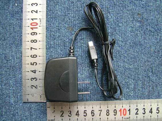
Click to zoom
Application Details
- Equipment Class
- PCE - PCS Licensed Transmitter held to ear
- Date of Grant
- Jul 11, 2006
- Application Purpose
- Original Equipment
- Date of Application
- Jul 11, 2006
- Equipment Note
- GSM handest
- Frequency Range
- 1850.20000000 - 1909.80000000
- Country
- China
Documents & Files
Document Text
Text extracted from the exhibit documents filed with the FCC. Open a document above to read the original.
Users Manual
V 2006-6-7 1/74 Discover Your Phone Screen Right softkey Alphanumeric keypad Left softkey Hang up key Navigation key & OK key Pick up key Earpiece V 2006-6-7 2/74 Charging Connector MP3 key Side down key Side up key Microphone V 2006-6-7 3/74 Camera Lens V 2006-6-7 4/74 CONTENT 1 - MAIN MENU 14 2 - GETTING STARTING 14 2.1. Inserting the SIM Card 14 2.1.1 Remove the back cover 14 2.1.2 Remove the battery 15 2.1.3 Insert the SIM card 15 2.2. Switch on the phone 16 2.3. Charging the Battery 17 3 - CALLING 17 3.1. Make a call 17 3.1.1 From the idle screen 17 3.1.2 Using the phonebook 17 3.2. Answer and end a call 18 3.2.1 Call handfree 18 3.3. Options during a call 19 3.3.1 Activate handsfree 19 3.3.2 Mute or Unmute 19 3.3.3 Record dialogue 19 3.4. Handing multiple calls 19 3.4.1 Making a second call 19 3.4.2 Answering a second call 20 3.4.3 Answering a third call 20 V 2006-6-7 5/74 4 - TEXT ENTRY 21 4.1. T9® text English input 21 4.2. Basic text input 22 5 - TOOLBOX 23 5.1. Calculator 24 5.2. Organizer 24 5.2.1 Creating a new event 24 5.2.2 Deleting old events 25 5.2.3 Managing events 25 5.2.4 Events views 25 5.3. Alarm clock 25 5.3.1 Snooze mode 26 5.4. Format T-flash 26 6 - MY STUFF 27 6.1. Memory status 27 6.2. Sound album 27 6.3. Picture album 28 6.4. Sound recording 29 7 - ENTERTAINMENT 30 7.1. MP3 Player 30 7.2. KTV Player 30 V 2006-6-7 6/74 7.3. Camera 31 7.3.1 Activate the camera 31 7.3.2 Take a picture 32 7.3.3 Picture List 32 7.3.4 Picture orientation 33 7.3.5 Color mode 33 7.3.6 Environment 33 7.3.7 Self-Timer 33 7.3.8 Resolution 34 7.3.9 Picture quality 34 7.3.10 Shutter Sound 34 7.3.11 Reset settings 34 7.3.12 Rotate 34 7.3.13 Flip 35 7.3.14 Picture location 35 7.4. Continuous shoot 35 7.5. Video 36 8 - WAP 36 8.1. Homepage 37 8.2. Bookmarks 37 8.3. Go to URL 38 8.4. Settings 38 8.4.1 Select profile 38 8.4.2 Browser options 38 8.4.3 Rename profile 38 8.4.4 Cookies 39 V 2006-6-7 7/74 8.4.5 Cache 39 8.4.6 Network 39 8.5. Push inbox 39 9 - MESSAGE 40 9.1. Broadcast SMS 40 9.2. SMS 41 9.2.1 New SMS 41 9.2.2 Settings 41 9.2.3 Archive 42 9.2.4 SMS Inbox 42 9.3. MMS 43 9.3.1 Receiving MMS 44 9.3.2 Create New MMS 44 9.3.3 Inbox 45 9.3.4 Drafts 45 9.3.5 Templates 46 9.3.6 Outbox 46 9.3.7 MMS Settings 46 9.4. Services 46 10 - SETTINGS 46 10.1. Time and date 47 10.1.1 Set time 47 10.1.2 Set date 47 10.1.3 Time zone 47 10.1.4 Daylight saving 47 V 2006-6-7 8/74 10.1.5 Date format 47 10.2. Sounds 48 10.2.1 Ringer volume 48 10.2.2 Ringtone 48 10.2.3 Messages ringer 48 10.2.4 Equalizer 48 10.2.5 Key tones 48 10.2.6 Sounds alerts 48 10.2.7 Vibra alert 49 10.2.8 Silent 49 10.3. Security 49 10.3.1 Keypad lock 49 10.3.2 Change codes 50 10.3.3 PIN protection 50 10.3.4 Public names 50 10.3.5 Call barring 51 10.4. Network 51 10.4.1 Access settings 51 10.4.2 GPRS attach 52 10.4.3 Register again 52 10.4.4 Preferred list 53 10.5. Profiles 53 10.6. Call setting 54 10.6.1 Info at call endding 54 10.6.2 Any key answer 55 10.6.3 Calling waiting 55 10.6.4 Caller ID 55 V 2006-6-7 9/74 10.6.5 Call forward 55 10.6.6 Mailboxes 56 10.6.7 Auto redial 56 10.7. Display 56 10.7.1 Wallpaper 56 10.7.2 Backlight 56 10.7.3 Language 57 10.7.4 Animation 57 10.8. Phonesettings 57 10.8.1 Auto Switch on/off 57 10.8.2 Hotkeys 57 11 - CONTACTS 58 11.1. Settings 58 11.1.1 Delete all 58 11.1.2 Contacts select 59 11.1.3 Copy to phone 59 11.1.4 Groups setting 59 11.2. Names list 59 11.2.1 Adding contacts to the SIM phonebook 60 11.2.2 Adding contacts in the phone phonebook 60 11.2.3 Edit and manage contacts 60 11.2.4 In the SIM phonebook 61 11.2.5 In the onboard phonebook 61 12 - CALL INFO 63 12.1. Counters 63 V 2006-6-7 10/74 12.1.1 GPRS counters 63 12.1.2 GSM counters 63 12.2. Call list 64 12.2.1 Reset 64 12.2.2 Call list 64 13 - GAMES 65 13.1. Brick games 65 14 - ICON & SYMBOLS 65 15 - PRECAUTIONS 66 15.1. Radio waving 66 15.2. Always switch off your phone... 67 15.3. Pacemakers 67 15.4. Hearing aids 68 15.5. Improved performance 68 15.6. Battery information 68 15.7. Your mobile phone and your car 69 15.8. EN 60950 Norm 69 15.9. Environmental care 70 16 - TROUBLESHOOTING 70 16.1. The phone does not switch on 70 V 2006-6-7 11/74 16.2. The display shows BLOCKED when you switch on 70 16.3. The display shows IMSI failure 70 16.4. Your phone doesn’t return to the idle screen 70 16.5. The network symbol is not displayed 71 16.6. The display doesn’t respond to key presses 71 16.7. Your battery seems to over heat 71 16.8. Your phone doesn’t display the phone numbers of incoming calls 71 16.9. You can’t send text messages 71 16.10. You can’t receive and / or store JPEG pictures 72 16.11. You have the feeling that you miss some calls 72 16.12. The display shows SIM failure 72 16.13. The display shows INSERT YOUR SIM CARD 72 16.14. The autonomy of your phone seems lower that indicated in the user guide 72 16.15. Your phone doesn’t work well in your car 73 16.16. Your phone is not charging 73 V 2006-6-7 12/74 General Information [Caution] Changes or modifications made in the radio phone, not expressly approved by UTstarcom, will void the user's authority to operate the equipment. [RF Energy Interference/Compatibility] This device complies with Part 15 of the FCC Rules. Operation is subject to the following two conditions: (1) this device may not cause harmful interference, and (2) this device must accept any interference received, including interference that may cause undesired operation. [What's in the Box?] Your wireless mobile phone comes with a battery, charger, USB data cable, headset, companion CD, user manual, product and service user data. You can purchase other accessories to customize your phone for maximum performance and portability. [Body-worn operation] To maintain compliance with FCC RF exposure guidelines, if you wear a radio product on your body when transmitting, always place the radio product in a UTstarcom approved clip, holder, holster, case or body harness for this product. Use of non-UTstarcom-approved accessories may…
Text truncated - open the document above for the full version.
Cover Letter(s)
Cellon (Shenzhen) Co.,Ltd. Date: June 9, 2006 PHOENIX TESTLAB GmbH Product Certification Königswinkel 10 D 32825 Blomberg RE: Certification Application FCC ID: T38UT1200 Confidentiality Request Pursuant to Section 0.459 & 0.457 of the Commission’s Rule, Cellon (China) Co.,Ltd. hereby requests confidential treatment of information accompanying this Application as outlined below: - Block Diagram - Schematics - Operational Description The above materials contain trade secrets and proprietary information not customarily released to the prublic. The public disclosure of these matters might be harmful to Cellon (China) Co.,Ltd. and provide unjustified benefits to its competitors. Thank you for your attention in this matter. Yours Sincerely, David Tian Project Manager Cellon (China) Co.,Ltd.
Cover Letter(s)
Notified Body Königswinkel 10 D-32825 Blomberg, Germany Phone +49 (0) 52 35 95 00-24 Fax +49 (0) 52 35 95 00-28 [email protected] www.phoenix-testlab.de Ersteller: H. Bentje Revision: 01 Erstelldatum: 03.01.02 Datum: 02.04.04 E:\Project\FCC\cellon\SZ_Cellon_0605_FCC\1.letters\T38UT1200__ApplicantLetter.doc Seite 1 von 6 General Checklist and Application Form for Low Power Transmitters subject to FCC CERTIFICATION regulations The following items need to be submitted in electronic format for Certification application. The applicable formats are described in the PHOENIX TESTLAB TCB User’s Manual. All letters have to be signed by an authorised signatory. Use this checklist to evaluate your application. Please note, that the Applicant’s Statement is part of the application. Applicant Cellon(Shenzhen)Co.,Ltd Company Address 13/F, Skyworth C Building, Gaoxin S.Ave1, Hi-Tech Industrial Park, Nanshan, Shenzhen Contact person Xinglan Yu E-Mail Xinglan.yu@cecwirele ss.com.cn Website/ Company URL Phone +86-10-58270277 Fax +86-10-84568718 Agent of the Applicant, if applicable Morlab Company (Agent) Address Electronic Testing Building, Shahe Road, Xili Town, Shenzhen, P.R.China Contact person Wu Xuewen E-Mail [email protected] n Website / Company URL www.morlab.cn Phone +86 0755 86130298-3011 Fax +86 0755 86130218 The applicant is listed in the FCC database: Yes No Applicant/Grantee Code (MUST be obtained, refer to the FCC website http://www.fcc.gov) T38 FCC Identifier (FCC ID) of the product, if applicable T38UT1200 Specific Rule Selection applied for (e.g. Section 15.247) P22E,p24E Product Details Short Description GSM handset Type or Model Name GPRS1228 Brand Name UTStarcom Shenzhen, June 9, 2006 Place, Date Signature and Stamp - 2 - Applicant’s Statement Cellon(China)Co.,Ltd (hereinafter the “Applicant”) accept the following terms as provided in this Telecommunication Certification Body Agreement. The Applicant authorizes PHOENIX TESTLAB GmbH (hereinafter “PTL”) to perform the required certification and testing in compliance with the current Federal Communications Commission (FCC) regulations. 1. Certificate. The Applicant shall endeavour to ensure that no certificate or report or any part thereof is used in a misleading manner. Equipment shall be represented as certified only if it complies with the FCC regulations and is labelled as required by the FCC. The Applicant will use the certification only to indicate that the respective products are certified in conformity with the specified FCC regulations. 2. Conformity: The equipment, represented, as certified shall comply with all of the FCC technical and administrative requirements. 3. Audits: PTL is authorized to perform audits of the Applicant's equipment and documentation. The Applicant shall make all necessary arrangements for the conduct of the audit and/or evaluation, including provision for examining documentation and access to records (especially to internal audit reports) and personnel for the purpose of evaluation (including but not limited to: testing, inspection, assessment, surveillance, reassessment) and resolution of complaints. 4. Forwarded information: The Applicant is liable that all information, including but not limited to specifications, company information, technical data, testing data etc., given and to be given to PTL are correct, complete, and verifiable. 5. Samples: PTL attempts to keep the need for samples to a minimum. However, if PTL requests samples from time to time for examination and testing purposes from the Applicant, the Applicant shall furnish such samples of the respective equipment without charge. If requested by the Applicant PLT will return the samples at the Applicant's expense. PTL shall not be responsible for the condition of the samples. The samples may be damaged or destroyed during testing. 6. Testing and Certification: The rights of PTL under this Agreement do not relieve the Applicant of any part of its obligations under this Agreement. The Applicant recognizes that the opinions and findings of PTL represent its judgment given with due consideration to the type of certification, the necessary limitations of practical and in accordance with its objects and purposes. The Applicant recognizes that many tests specified in the FCC requirements may be inherently hazardous and agrees that PTL neither assumes nor accepts any responsibility for any injury or damage to the Applicant's property or personnel that may occur during or as a result of tests, whether performed in whole or in part by the Applicant or PTL, and whether or not any device, test equipment, facility or personnel for or in connection with the test is furnished by the Applicant or PTL. Ersteller: H. Bentje Revision: 02 Erstelldatum: 03.01.02 Datum: 24.05.05 Seite 2 von 6 - 3 - 7. Notification to PTL: The Applicant shall notify PTL immediately if the Applicant discovers that the equipment has been or may have been the cause of harm to any telephone network, harmful interference, or of personal injury or property damage. In cases where the results of examination by an agency other than PTL were relied upon by PTL for certification of the equipment, the Applicant shall notify PTL if the Applicant subsequently discovers said results to be invalid. 8. Complaints: The Applicant shall keep a record of all complaints made known to the supplier relating to a product’s compliance with the requirements of the relevant standard. On request, the Applicant will make these records available to PTL. 9. Actions Resulting from Complaints: The Applicant shall take appropriate action with respect to such complaints and any deficiencies found in products or services that affect compliance with the requirement for certification. The Applicant shall document actions taken. 10. Termination: A TCB may revoke a certification grant during the first 30 days after the grant is issued pursuant to all conditions outlined by the FCC requirements. During this…
Text truncated - open the document above for the full version.
External Photos
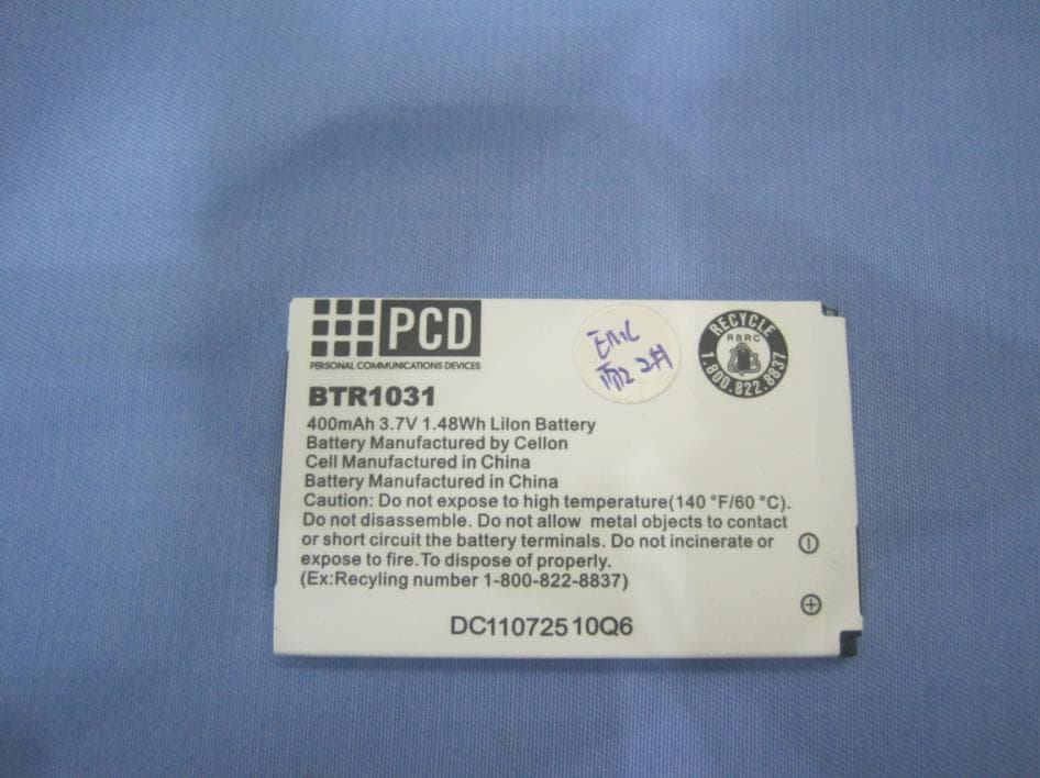
External Photos 1. Front View of EUT 2. Inside View of EUT 3. Back View of EUT 4. AC adapter 5. Side View
ID Label/Location Info
MADE IN CHINA MODEL: GPRS1228 FCC ID: T38UT1200 S/N : 01051025123456 IMEI : 00 0000 00 000 00 0000000 00 00
Internal Photos
Internal Photos
RF Exposure Info
Report No. SN0093_900 March 2006 INDEXSAR 900MHz validation Dipole Type IXD-090 S/N 0093 Performance measurements MI Manning Indexsar, Oakfield House, Cudworth Lane, Newdigate, Surrey RH5 5BG. UK. Tel: +44 (0) 1306 632870 Fax: +44 (0) 1306 631834 e-mail: [email protected] 1. Measurement Conditions Measurements were performed using a box-shaped phantom made of PMMA with dimensions designed to meet the accuracy criteria for reasonably-sized phantoms that do not have liquid capacities substantially in excess of the volume of liquid required to fill the Indexsar upright SAM phantoms used for SAR testing of handsets against the ear. An Anritsu MS4623B vector network analyser was used for the return loss measurements. The dipole was placed in a special holder made of low-permittivity, low-loss materials. This holder enables the dipole to be positioned accurately in the centre of the base of the Indexsar box-phantom used for flat-surface testing and validation checks. The validation dipoles are supplied with special spacers made from a low- permittivity, low-loss foam material. These spacers are fitted to the dipole arms to ensure that, when the dipole is offered up to the phantom surface, the spacing between the dipole and the liquid surface is accurately aligned according to the guidance in the relevant standards documentation. The spacers are rectangular with a central hole equal to the dipole arm diameter and dimensioned so that the longer side can be used to ensure a spacing of 15mm from the liquid in the phantom (for tests at 900MHz and below) and the shorter side can be used for tests at 1800MHz and above to ensure a spacing of 10mm from the liquid in the phantom. The spacers are made on a CNC milling machine with an accuracy of 1/40 th mm but they may suffer wear and tear and need to be replaced periodically. The material used is Rohacell, which has a relative permittivity of approx. 1.05 and a negligible loss tangent. The apparatus supplied by Indexsar for dipole validation tests thus includes: Balanced dipoles for each frequency required are dimensioned according to the guidelines given in IEEE 1528 [1]. The dipoles are made from semi-rigid 50 Ohm co-ax, which is joined by soldering and is gold-plated subsequently. The constructed dipoles are easily deformed, if mis-handled, and periodic checks need to be made of their symmetry. Rohacell foam spacers designed for presenting the dipoles to 2mm thick PMMA box phantoms. These components also suffer wear and tear and should be replaced when the central hole is a loose-fit on the dipole arms or if the edges are too worn to ensure accurate alignment. The standard spacers are dimensioned for use with 2mm wall thickness (additional spacers are available for 4mm wall thickness). 2. Typical SAR Measurement A SAR validation check is performed with the box-phantom located on the SARA2 phantom support base on the SARA2 robot system. Tests are then conducted at a feed power level of approx. 0.25W. The actual power level is recorded and used to normalise the results obtained to the standard input power conditions of 1W (forward power). The ambient temperature is 21 o C +/- 1 o C and the relative humidity is around 40% during the measurements. The phantom is filled with a 900MHz brain liquid using a recipe from [1], which has the following electrical parameters (measured using an Indexsar DiLine kit) at 900MHz: Relative Permittivity 42.5 Conductivity 0.96 S/m The SARA2 software version VPM2.2 is used with an Indexsar probe previously calibrated using waveguides. The 3D measurements made using the dipole at the bottom of the phantom box is shown below: The results, normalised to an input power of 1W (forward power) are typically: Averaged over 1 cm3 (1g) of tissue 10.55 W/kg Averaged over 10cm3 (10g) of tissue 6.80 W/kg These results can be compared with Table 8.1 in [1]. The agreement is within 10%. 3. Dipole impedance and return loss The dipoles are designed to have low return loss ONLY when presented against a lossy-phantom at the specified distance. A Vector Network Analyser (VNA) was used to perform a return loss measurement on the specific dipole when in the measurement-location against the box phantom. The distance was as specified in the standard i.e. 10mm from the liquid (for 900MHz). The Indexsar foam spacers (described above) were used to ensure this condition during measurement. The impedance was measured at the SMA-connector with the network analyser. The following parameters were measured: Dipole impedance at 900 MHz Re{Z} = 49.999 Ω Im{Z} = 631.313 μΩ Return loss at 900MHz -20.416 dB 4. Dipole handling The dipoles are made from standard, copper-sheathed coaxial cable. In assembly, the sections are joined using ordinary soft-soldering. This is necessary to avoid excessive heat input in manufacture, which would destroy the polythene dielectric used for the cable. The consequence of the construction material and the assembly technique is that the dipoles are fragile and can be deformed by rough handling. Conversely, they can be straightened quite easily as described in this report. If a dipole is suspected of being deformed, a normal workshop lathe can be used as an alignment jig to restore the symmetry. To do this, the dipole is first placed in the headstock of the lathe (centred on the plastic or brass spacers) and the headstock is rotated by hand (do NOT use the motor). A marker (lathe tool or similar) is brought up close to the end of one dipole arm and then the headstock is rotated by 0.5 rev. to check the opposing arm. If they are not balanced, judicious deformation of the arms can be used to restore the symmetry. If a dipole has a failed solder joint, the dipole can be fixed down in such a way that the arms are co-linear and the joint re-soldered with a reasonably-powerful electrical soldering iron. Do not use gas soldering irons. After such a repair, electrical tests must be performed as described below. Please note that, beca…
Text truncated - open the document above for the full version.
RF Exposure Info
Report No. SN0112_1900 March 2006 INDEXSAR 1900MHz validation Dipole Type IXD-080 S/N 0112 Performance measurements MI Manning Indexsar, Oakfield House, Cudworth Lane, Newdigate, Surrey RH5 5BG. UK. Tel: +44 (0) 1306 633870 Fax: +44 (0) 1306 631834 e-mail: [email protected] 1. Measurement Conditions Measurements were performed using a box-shaped phantom made of PMMA with dimensions designed to meet the accuracy criteria for reasonably-sized phantoms that do not have liquid capacities substantially in excess of the volume of liquid required to fill the Indexsar upright SAM phantoms used for SAR testing of handsets against the ear. An Anritsu MS4623B vector network analyser was used for the return loss measurements. The dipole was placed in a special holder made of low-permittivity, low-loss materials. This holder enables the dipole to be positioned accurately in the centre of the base of the Indexsar box-phantom used for flat-surface testing and validation checks. The validation dipoles are supplied with special spacers made from a low- permittivity, low-loss foam material. These spacers are fitted to the dipole arms to ensure that, when the dipole is offered up to the phantom surface, the spacing between the dipole and the liquid surface is accurately aligned according to the guidance in the relevant standards documentation. The spacers are rectangular with a central hole equal to the dipole arm diameter and dimensioned so that the longer side can be used to ensure a spacing of 15mm from the liquid in the phantom (for tests at 900MHz and below) and the shorter side can be used for tests at 1800MHz and above to ensure a spacing of 10mm from the liquid in the phantom. The spacers are made on a CNC milling machine with an accuracy of 1/40 th mm but they may suffer wear and tear and need to be replaced periodically. The material used is Rohacell, which has a relative permittivity of approx. 1.05 and a negligible loss tangent. The apparatus supplied by Indexsar for dipole validation tests thus includes: Balanced dipoles for each frequency required are dimensioned according to the guidelines given in IEEE 1528 [1]. The dipoles are made from semi-rigid 50 Ohm co-ax, which is joined by soldering and is gold-plated subsequently. The constructed dipoles are easily deformed, if mis-handled, and periodic checks need to be made of their symmetry. Rohacell foam spacers designed for presenting the dipoles to 2mm thick PMMA box phantoms. These components also suffer wear and tear and should be replaced when the central hole is a loose-fit on the dipole arms or if the edges are too worn to ensure accurate alignment. The standard spacers are dimensioned for use with 2mm wall thickness (additional spacers are available for 4mm wall thickness). 2. Typical SAR Measurement A SAR validation check is performed with the box-phantom located on the SARA2 phantom support base on the SARA2 robot system. Tests are then conducted at a feed power level of approx. 0.25W. The actual power level is recorded and used to normalise the results obtained to the standard input power conditions of 1W (forward power). The ambient temperature is 22 o C +/- 1 o C and the relative humidity is around 40% during the measurements. The phantom is filled with a 1900MHz brain liquid using a recipe from [1], which has the following electrical parameters (measured using an Indexsar DiLine kit) at 1900MHz: Relative Permittivity 41.4 Conductivity 1.85 S/m The SARA2 software version 2.2 VPM is used with an Indexsar probe previously calibrated using waveguides. The 3D measurements made using the dipole at the bottom of the phantom box is shown below: The results, normalised to an input power of 1W (forward power) are typically: Averaged over 1 cm3 (1g) of tissue 4.928 W/kg Averaged over 10cm3 (10g) of tissue 2.362 W/kg These results can be compared with Table 8.1 in [1]. The agreement is within 10%. 3. Dipole impedance and return loss The dipoles are designed to have low return loss ONLY when presented against a lossy-phantom at the specified distance. A Vector Network Analyser (VNA) was used to perform a return loss measurement on the specific dipole when in the measurement-location against the box phantom. The distance was as specified in the standard i.e. 10mm from the liquid (for 1900MHz). The Indexsar foam spacers (described above) were used to ensure this condition during measurement. The impedance was measured at the SMA-connector with the network analyser. The following parameters were measured: Dipole impedance at 1900 MHz Re{Z} = 49.996 Ω Im{Z} = 15.160 mΩ Return loss at 1900MHz -26.175 dB 4. Dipole handling The dipoles are made from standard, copper-sheathed coaxial cable. In assembly, the sections are joined using ordinary soft-soldering. This is necessary to avoid excessive heat input in manufacture, which would destroy the polythene dielectric used for the cable. The consequence of the construction material and the assembly technique is that the dipoles are fragile and can be deformed by rough handling. Conversely, they can be straightened quite easily as described in this report. If a dipole is suspected of being deformed, a normal workshop lathe can be used as an alignment jig to restore the symmetry. To do this, the dipole is first placed in the headstock of the lathe (centred on the plastic or brass spacers) and the headstock is rotated by hand (do NOT use the motor). A marker (lathe tool or similar) is brought up close to the end of one dipole arm and then the headstock is rotated by 0.5 rev. to check the opposing arm. If they are not balanced, judicious deformation of the arms can be used to restore the symmetry. If a dipole has a failed solder joint, the dipole can be fixed down in such a way that the arms are co-linear and the joint re-soldered with a reasonably-powerful electrical soldering iron. Do not use gas soldering irons. After such a repair, electrical tests must be performed as described below. Please note th…
Text truncated - open the document above for the full version.
RF Exposure Info
IMMERSIBLE SAR PROBE CALIBRATION REPORT Part Number: IXP – 050 S/N 0177 March 2006 Indexsar Limited Oakfield House Cudworth Lane Newdigate Surrey RH5 5BG Tel: +44 (0) 1306 632 870 Fax: +44 (0) 1306 631 834 e-mail: [email protected] Page 1 of 19 Page 2 of 19 INTRODUCTION This Report presents measured calibration data for a particular Indexsar SAR probe (S/N 0177) and describes the procedures used for characterisation and calibration. Indexsar probes are characterised using procedures that, where applicable, follow the recommendations of CENELEC [1] and IEEE [2] standards. The procedures incorporate techniques for probe linearisation, isotropy assessment and determination of liquid factors (conversion factors). Calibrations are determined by comparing probe readings with analytical computations in canonical test geometries (waveguides) using normalised power inputs. Each step of the calibration procedure and the equipment used is described in the sections below. CALIBRATION PROCEDURE 1. Objectives The calibration process comprises three stages 1) Determination of the channel sensitivity factors which optimise the probe’s overall rotational isotropy in 1800MHz brain fluid 2) At each frequency of interest, application of these channel sensitivity factors to model the exponential decay of SAR in a waveguide fluid cell, and hence derive the liquid conversion factors at that frequency 3) Determination of the effective tip radius and angular offset of the X channel which together optimise the probe’s spherical isotropy in 900MHz brain fluid 2. Probe output The probe channel output signals are linearised in the manner set out in Refs [1] and [2]. The following equation is utilized for each channel: U lin = U o/p + U o/p 2 / DCP (1) where U lin is the linearised signal, U o/p is the raw output signal in voltage units and DCP is the diode compression potential in similar voltage units. DCP is determined from fitting equation (1) to measurements of U lin versus source feed power over the full dynamic range of the probe. The DCP is a characteristic of the Schottky diodes used as the sensors. For the IXP-050 probes with CW signals the DCP values are typically 0.10V (or 20 in the voltage units used by Indexsar software, which are V*200). In turn, measurements of E-field are determined using the following equation (where output voltages are also in units of V*200): Page 3 of 19 E liq 2 (V/m) = U linx * Air Factor x * Liq Factor x + U liny * Air Factor y * Liq Factor y + U linz * Air Factor z * Liq Factor z (3) Here, “Air Factor” represents each channel’s sensitivity, while “Liq Factor” represents the enhancement in signal level when the probe is immersed in tissue-simulant liquids at each frequency of interest. 3. Selecting channel sensitivity factors to optimise isotropic response After manufacture, the first stage of the calibration process is to balance the three channels’ Air Factor values, thereby optimising the probe’s overall axial response (“rotational isotropy”). To do this, an 1800MHz waveguide containing head-fluid simulant is selected. Like all waveguides used during probe calibration, this particular waveguide contains two distinct sections: an air-filled launcher section, and a liquid cell section, separated by a dielectric matching window designed to minimise reflections at the air-liquid interface. The waveguide stands in an upright position and the liquid cell section is filled with 1800MHz brain fluid to within 10 mm of the open end. The depth of liquid ensures there is negligible radiation from the waveguide open top and that the probe calibration is not influenced by reflections from nearby objects. During the measurement, a TE 01 mode is launched into the waveguide by means of an N-type-to-waveguide adapter. The probe is then lowered vertically into the liquid until the tip is exactly 10mm above the centre of the dielectric window. This particular separation ensures that the probe is operating in a part of the waveguide where boundary corrections are not necessary. Care must also be taken that the probe tip is centred while rotating. The exact power applied to the input of the waveguide during this stage of the probe calibration is immaterial since only relative values are of interest while the probe rotates. However, the power must be sufficiently above the noise floor and free from drift. The dedicated Indexsar calibration software rotates the probe in 10 degree steps about its axis, and at each position, an Indexsar ‘Fast’ amplifier samples the probe channels 500 times per second for 0.4 s. The raw U o/p data from each sample are packed into 10 bytes and transmitted back to the PC controller via an optical cable. U linx , U liny and U linz are derived from the raw U o/p values and written to an Excel template. Once data have been collected from a full probe rotation, the Air Factors are adjusted using a special Excel Solver routine to equalise the output from each channel …
Text truncated - open the document above for the full version.
Contact Information
Applicant
maggie xu(TA manager)
Test Firm
ShenZhen Electronic Product Quality Testing CenterXingsun Lin
Technical Specifications
| # | Rule Parts | Frequency Range | Power Output | Emission | Tolerance |
|---|---|---|---|---|---|
| 2 | 24E | 1.85 GHz - 1.91 GHz | 337.00 mW | 300KGXW | 0.1 ppm |
Other Applications from Cellon Communications Technology (Shenzhen) Co.,Ltd.
T38C1037
Aug 22, 2013GSM quad band mobile phone
Equipment Class
PCE - PCS Licensed Transmitter held to ear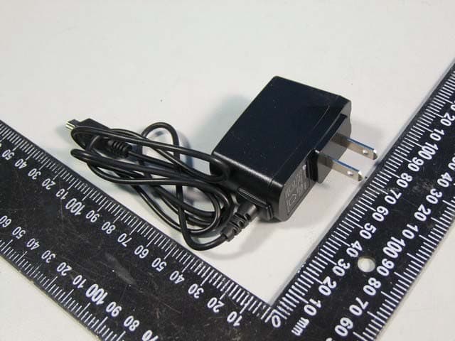
T38C1021ECL
Jul 28, 2013GSM850/1900 Moblie Phone
Equipment Class
PCE - PCS Licensed Transmitter held to ear
T38C8666GP
Apr 18, 2013GSM/GPRS/WCDMA/BT/WIFI/GPS Mobile Phone
Equipment Class
JBP - Part 15 Class B Computing Device Peripheral
T38C8680EK
Mar 26, 2013WCDMA mobile phone
Equipment Class
DSS - Part 15 Spread Spectrum Transmitter
T38C8680GP
Jan 27, 2013WCDMA mobile phone
Equipment Class
JBP - Part 15 Class B Computing Device Peripheral