T39SLC10100RFID CF TYPE READER
Sunlit System Technology Corp.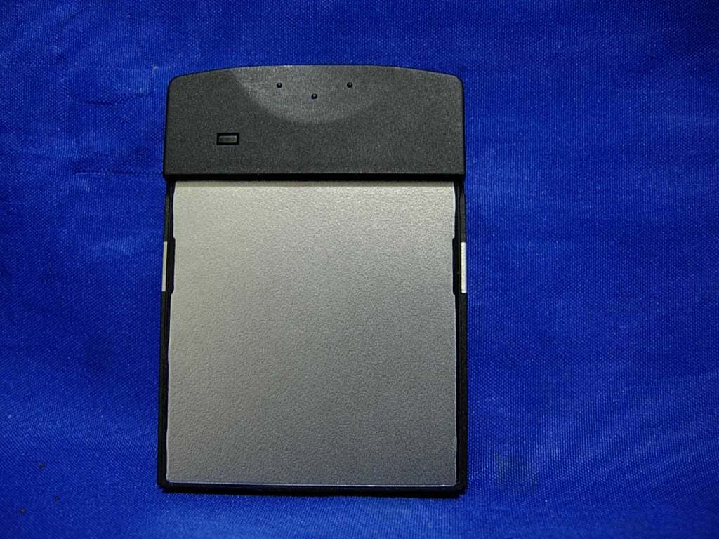
Click to zoom
Application Details
- Equipment Class
- DSS - Part 15 Spread Spectrum Transmitter
- Date of Grant
- Apr 29, 2007
- Application Purpose
- Original Equipment
- Date of Application
- Apr 29, 2007
- Equipment Note
- RFID CF TYPE READER
- Frequency Range
- 2402.00000000 - 2477.00000000
- Country
- Taiwan
Documents & Files
Document Text
Text extracted from the exhibit documents filed with the FCC. Open a document above to read the original.
Users Manual
-1 RFID CF Type Reader User’s Guide Model Name: SLC-10100 Version: 1.0 Date: 2007.04.09 -2 Content No. Item Page 1 Hardware 3 2 Demo software 6 3 API user’s guide 15 4 Source code of demo program 36 5 Disk information 42 6 Package list 42 7 How to contact us 42 Notice: In order to avoid misuse or any unexpected damage, please read this guide first. This device complies with Part 15 of FCC Rules. Operation is subject to the following two conditions: (1)This device may not cause harmful interference, and (2)This device must accept any interference received, including interference that may cause undesired operation -3 1. Hardware environment (1) Product introduction Sunlit’s RFID CF type reader is based on Hitachi μ-solution to develop. It was operated at microwave 2.45GHz frequency band. This is small and light, can be easily install to PDA, tablet PC. (2) Specification Power Supply DC 3V from PDA or PC Operating Environment 0°C ~40°C Storage Environment 0°C ~60°C Power Consumption Max. 0.6 W Dimensions 56 x 43 x 6.1 (mm x mm x mm) RF Output Power 36.307 mW Frequency Range 2.402GHZ~2.477GHZ Baud Rate 4800 b/s Reading Distance About 5 cm -4 (3) Hardware structure CF interface PDA or other compatible device RFID CF reader Tag WindowCE Platform (4) Hardware appearance introduction (5) System requirement Item Condition Quantity Hardware requirement PDA support CF interface1 Platform requirement Windows Pocket PC 20031 Antenna inside CF interface connecter -5 (6) How to install reader Face the side with LED up, and insert it into PDA CF slot as shown in picture. Normally always insert CF reader by put LED side up, but some PDA put CF slot at reverse side, it means user needs to insert CF reader at back side. (LED down) -6 2. Demo software environment (1) Demo software introduction This demo program can build a database include TAG ID、TAG information and picture. It can be use to demo ex. material manager、In/out control for people... etc. (2) Block diagram Main Program Tag ID Data base PictureInformation (3) Demo program operation System requirement Item Condition Quantity PDA Support CF interface 64MB Flash ROM 64 MB RAM 1 System platform Windows Pocket PC 20031 RFID CF reader 1 Tag Include Hitachi μ-chip inlet1 -7 Demo software contents Item Description Development tool Microsoft Visual Studio 2005 Traditional Edition WinceDEMO.exe Main program sunlitrfidppc.dll Dynamic Link Library file Database.txt ID database file after ID saved File contents PIC [Folder] A picture file includes different pictures which correlated with each individual ID Main Program Window Function Description Function Description ID Display Tag ID when Tag be read. Delete Delete registered database Information Edit information about Tag ID Mode Select scan mode Open Open/Close comport of reader Picture Select picture correct with ID Mute ON/Off reading sound Clear Clear text of ID & Message window Read Trigger reader to scan Tag DataBase Display registered database Updata Save registered database Message Display status of reader -8 Demo program operation (a) Copy demo program files “WinceDEMO.exe” & “sunlitrfidppc.dll” to PDA and store at same directory. About the file ※transmissions please refer to PDA user’s manual. (b) Plug reader in CF slot of PDA -9 (c) Click file “WinceDEMO.exe” and click “Open” to open device(Reader) (d) Create a ID data base Be sure the Mode is “Passive” Put the tag on front side of reader, click “Read” to scan Tag ID and checking ID number is showing on ID window. Mark the ID number in Tag DataBase field . Click “Picture”→ “Folder” to open location of picture that you want to correct with Tag ID.Click ”Type” to select file type that you want than click picture file ※ Operation mode: Passive: Click Read once and reader will scan once. Active: Click Read once and reader will scan continuously. It mean open device successful 1 2 Cancel Folder File type 3 4 5 Mark this field 3 -10 (e) Editing information about the ID number on “Information” window. Click “Updata” and check “Tag DataBase” window to complete the data base created procedure. (f) You can follow the step (d) (e) to create some data base that you want. (g) When you created the data base, the system was created 1 folder and 1 text file: Item Description SDB [text file] ID database file after ID saved SDB [Folder] A picture file storage folder about correlate with ID database after picture saved. Caution: Every PDA are different resolution so the picture is showed different size. If you want it to be matched, you should modify the source code of the project. And showing picture is Windows API,but it is not stable. Showing picture seveval times may cause the Demo AP crashes. 1 2 It mean database created successful -11 (h) Set Mute function Follow the figure click the” Mute” function check box, the mute function will enable. When you created the data base, the system was created 1 folder and 1 text file -12 (i) Set Operation mode Mode: Active Click the “Mode” combo box and select “Active” item to enable active function Click “Read”, if tag scanned by reader and the scan procedures will continuously. Mode: Passive Click “Mode” combo box select “Passive” item to enable passive function Click “Read” and the reader scanning just only once. Continue Scanning 1 2 -13 (j) Delete data base Click data you want to delete on Tag DataBase window Click “Delete” and select “Yes” to delete data. (k) Clear function If click “Clear” than the text message on the Message window will be clear. 1 2 3 -14 (l) Disable device(Reader) To confirm device is open. Click “Close” to disable device. -15 3. API user’s guide ONE:Structure of Sunlit RFID DLL for PPC TWO:Program Declaration THREE:FUNCTION Introduction FOUR:EVENTS Introduction APPENDIX:Development Environmen t -16 ONE、Structure of Sunlit RFID DLL for PPC The Sunlit RFID DLL has 18 functions. They can separate into 3 groups:Comport operation、Device operation and Device information: Comport operation functions inc…
Text truncated - open the document above for the full version.
Attestation Statements
Sunlit System Technology Corp. FCC ID.: T39SLC10100 8F., No. 19, Land 120, Sec. 1, Neihu Rd, Taipei Taiwan 114, R.O.C..Tel : 886-2-6600-6351#152 Federal Communications Commission April. 17, 2007 Authorization and Evaluation Division ATTESTATION FCC ID: T39SLC10100 Product: RFID CF Type Reader Model: SLC-10100 We don't provide any controls or software to allow operation outside the USA frequency band when we sell this product in USA. Sincerely, Eric Chang / Engineer Sunlit System Technology Corp.
Cover Letter(s)
Sunlit System Technology Corp. FCC ID.: T39SLC10100 8F., No. 19, Land 120, Sec. 1, Neihu Rd, Taipei Taiwan 114, R.O.C. Tel : 886-2-6600-6351#152 Sunlit System Technology Corp. 8F., No. 19, Land 120, Sec. 1, Neihu Rd, Taipei Taiwan 114, R.O.C. Tel : 886-2-6600-6351#152 Fax: 886-2-6600-6765 Federal Communications Commission April. 17, 2007 Authorization and Evaluation Division Confidentiality Request Pursuant to Sections 0.457 and 0.459 of the Commission’s Rules, the Applicant Hereby requests confidential treatment of information accompanying this Application As outlined below: Schematics, Block Diagram The above materials contain trade secrets and proprietary information not customarily Released to the public. The public disclosure of these matters might be harmful to the Applicant and provide unjustified benefits to its competitors. The Applicant understands that pursuant to Rule 0.457, disclosure of this Application and all accompanying documentation will not be made before the date of the Grant for this application. Sincerely, Eric Chang / Engineer Sunlit System Technology Corp.
External Photos
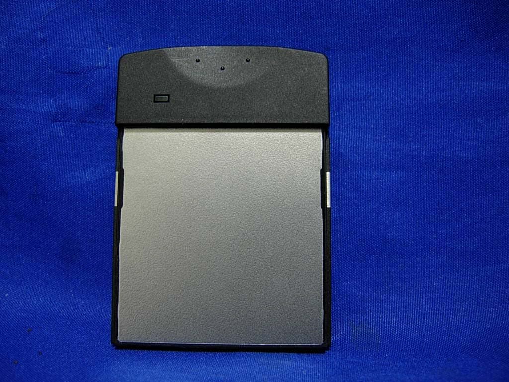
Report No.: 074L045-RFUSP05V01 Page : 1 of 4 Version:1.0 Attachment 2 : EUT Detailed Photographs (1) EUT Photo (2) EUT Photo
ID Label/Location Info
Sunlit System Technology Corp. FCC ID.: T39SLC10100 8F., No. 19, Land 120, Sec. 1, Neihu Rd, Taipei Taiwan 114, R.O.C..Tel : 886-2-6600-6351#152 FCC ID Label The FCC ID and DoC Label will be placed on the equipment as shown in the photograph below.
Internal Photos
Report No.: 074L045-RFUSP05V01 Page : 2 of 4 Version:1.0 (3) EUT Photo (4) EUT Photo Report No.: 074L045-RFUSP05V01 Page : 3 of 4 Version:1.0 (5) EUT Photo (6) EUT Photo Report No.: 074L045-RFUSP05V01 Page : 4 of 4 Version:1.0 (7) EUT Photo
Operational Description
Report No. 074L045-RFUSP05V01 Page: 7 of 45 Version:1.0 1.2. Operational Description The EUT is a RFID CF Type Reader with 76 channels. This device provides wireless technology that revolutionizes personal connectivity. It is the solution for the seamless integration of RFID technology into an automatic identification method, relying on storing and remotely retrieving data using devices called RFID tags or transponders This device uses frequency hopping spread spectrum modulation. The carries are synthesized by a 13MHz crystal.
RF Exposure Info
Report No. 074L054-RFUSP06V01 Page: 1 of 3 Version: 1.0 RF Exposure Evaluation declaration Product Name : RFID CF Type Reader Model No. : SLC-10100 FCC ID T39SLH10100 Applicant : Sunlit SystemTechnology Corp. Address : 8F., No. 19, Land 120, Sec. 1, Neihu Rd., Taipei 114, Taiwan, R.O.C. Date of Receipt : Apr. 03, 2007 Date of Declaration: Apr. 17, 2007 Report No. : 074L054-RFUSP06V01 The declaration results relate only to the samples calculated. The declaration shall not be reproduced except in full without the written approval of QuieTek Corporation. This report must not be used to claim product endorsement by NVLAP any agency of the U.S. Government Report No. 074L054-RFUSP06V01 Page: 2 of 3 Version: 1.0 1. RF Exposure Evaluation 1.1. Limits According to FCC 1.1310: The criteria listed in the following table shall be used to evaluate the environment impact of human exposure to radio frequency (RF) radiation as specified in 1.1307(b) LIMITS FOR MAXIMUM PERMISSIBLE EXPOSURE (MPE) Frequency Range (MHz) Electric Field Strength (V/m) Magnetic Field Strength (A/m) Power Density (mW/cm 2 ) Average Time (Minutes) (A) Limits for Occupational/ Control Exposures 300-1500 -- -- F/300 6 1500-100,000 -- -- 5 6 (B) Limits for General Population/ Uncontrolled Exposures 300-1500 -- -- F/1500 6 1500-100,000 -- -- 1 30 F= Frequency in MHz Friis Formula Friis transmission formula: Pd = (Pout*G)/(4*pi*r 2 ) Where Pd = power density in mW/cm 2 Pout = output power to antenna in mW G = gain of antenna in linear scale Pi = 3.1416 R = distance between observation point and center of the radiator in cm Pd id the limit of MPE, 1 mW/cm 2 . If we know the maximum gain of the antenna and the total power input to the antenna, through the calculation, we will know the distance r where the MPE limit is reached. 1.2. Test Procedure Software provided by client enabled the EUT to transmit and receive data at lowest, middle and highest channel individually. The temperature and related humidity: 18°Cand 78% RH. Report No. 074L054-RFUSP06V01 Page: 3 of 3 Version: 1.0 1.3. Test Result of RF Exposure Evaluation Product : RFID CF Type Reader Test Item : RF Exposure Evaluation Test Site : CTR1 Antenna Gain Antenna Gain: The maximum Gain measured in fully anechoic chamber is 0dBi in logarithm scale. Output Power Into Antenna & RF Exposure Evaluation Distance (0dBi): Channel Frequency (MHz) Output Power to Antenna (mW) Power Density at R = 20 cm (mW/cm2) 00 2402.00 25.6448 0.0051 38 2440.00 36.3078 0.0072 75 2477.00 21.1349 0.0042 The distance r (4 th column) calculated from the Fries transmission formula is far shorter than 20 cm separation requirement.
Test Report
Report No. 074L045-RFUSP05V01 Page: 1 of 45 Version:1.0 Test Report Product Name : RFID CF Type Reader Model No. : SLC-10100 FCC ID. : T39SLC10100 Applicant : Sunlit SystemTechnology Corp. Address : 8F., No. 19, Land 120, Sec. 1, Neihu Rd., Taipei 114, Taiwan R.O.C. Date of Receipt : Apr. 03, 2007 Issued Date : Apr. 17, 2007 Report No. : 074L045-RFUSP05V01 The Test Results relate only to the samples tested. The test report shall not be reproduced except in full without the written approval of QuieTek Corporation. This report must not be used to claim product endorsement by NVLAP any agency of the U.S. Government Report No. 074L045-RFUSP05V01 Page: 2 of 45 Version:1.0 Test Report Certification Issued Date: Apr. 17, 2007 Report No.: 074L045-RFUSP05V01 Product Name : RFID CF Type Reader Applicant : Sunlit SystemTechnology Corp. Address : 8F., No. 19, Land 120, Sec. 1, Neihu Rd., Taipei 114, Taiwan R.O.C. Manufacturer : Sunlit SystemTechnology Corp. Model No. : SLC-10100 FCC ID. : T39SLC10100 Rated Voltage : AC 120V/60Hz Working Voltage : DC 3.3V Trade Name : Sunlit Applicable Standard : FCC CFR Title 47 Part 15 Subpart C: 2005 ANSI C63.4: 2003 CISPR 22: 2005 Test Result : Complied The Test Results relate only to the samples tested. The test report shall not be reproduced except in full without the written approval of QuieTek Corporation. This report must not be used to claim product endorsement by NVLAP any agency of the U.S. Government Documented By : ( Genie Chang ) Tested By : ( Tom Hsieh ) Approved By : ( Gene Chang ) 0914 Accredited by NIST (NVLAP) NVLAP Lab Code: 200533-0 Report No. 074L045-RFUSP05V01 Page: 3 of 45 Version:1.0 TABLE OF CONTENTS Description Page 1. GENERAL INFORMATION ...............................................................................................................5 1.1. EUT Description......................................................................................................................................5 1.2. Operational Description...........................................................................................................................6 1.3. Tested System Details..............................................................................................................................7 1.4. Configuration of Tested System ..............................................................................................................7 1.5. EUT Exercise Software ...........................................................................................................................7 1.6. Test Facility .............................................................................................................................................8 2. CONDUCTED EMISSION ..................................................................................................................9 2.1. Test Equipment ........................................................................................................................................9 2.2. Test Setup ................................................................................................................................................9 2.3. Limits.....................................................................................................................................................10 2.4. Test Procedure .......................................................................................................................................10 2.5. Uncertainty ............................................................................................................................................10 2.6. Test Result of Conducted Emission .......................................................................................................11 3. PEAK POWER OUTPUT ..................................................................................................................13 3.1. Test Equipment ......................................................................................................................................13 3.2. Test Setup ..............................................................................................................................................13 3.3. Limit .................................................................................................................13 3.4. Uncertainty ............................................................................................................................................13 3.5. Test Result of Peak Power Output .........................................................................................................14 4. RADIATED EMISSION .....................................................................................................................15 4.1. Test Equipment ......................................................................................................................................15 4.2. Test Setup ..............................................................................................................................................16 4.3. Limits.....................................................................................................................................................16 4.4. Test Procedure .......................................................................................................................................17 4.5. Uncertainty ............................................................................................................................................17 4.6. Test Result of Radiated Emission ..........................................................................................................18 5. BAND EDGE .......................................................................................................................................22 5.1. Test Equipment ...............…
Text truncated - open the document above for the full version.
Test Setup Photos
Report No.: 074L045-RFUSP05V01 Page : 1 of 3 Version:1.0 Attachment 1: EUT Test Setup Photographs Front View of Conducted Test Back View of Conducted Test Report No.: 074L045-RFUSP05V01 Page : 2 of 3 Version:1.0 Front View of Radiated Test Back View of Radiated Test Report No.: 074L045-RFUSP05V01 Page : 3 of 3 Version:1.0 Front View of Radiated Test (Horn) Back View of Radiated Test (Horn)
Contact Information
Applicant
Vincent Su
Test Firm
DEKRA Testing and Certification Co., Ltd.Sky Hsu
Technical Specifications
| # | Rule Parts | Frequency Range | Power Output |
|---|---|---|---|
| 1 | 15C | 2.40 GHz - 2.48 GHz | 36.00 mW |
Other Applications from Sunlit System Technology Corp.
T39SLC11100
May 28, 2007RFID CF Type Reader
Equipment Class
DSS - Part 15 Spread Spectrum Transmitter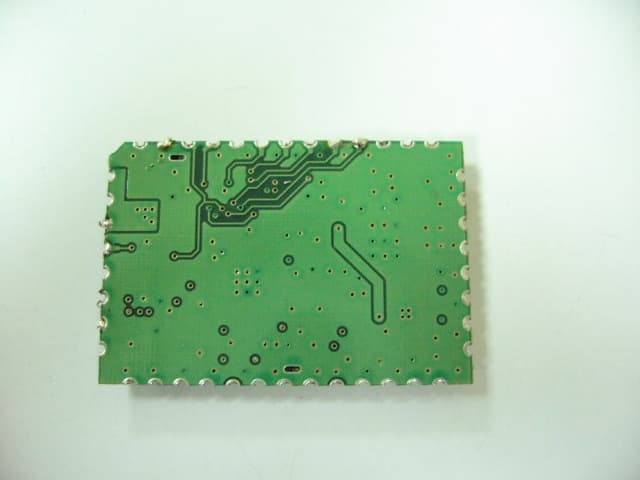
T39SLF10100
Feb 04, 2007RF Module v4.0
Equipment Class
DSS - Part 15 Spread Spectrum Transmitter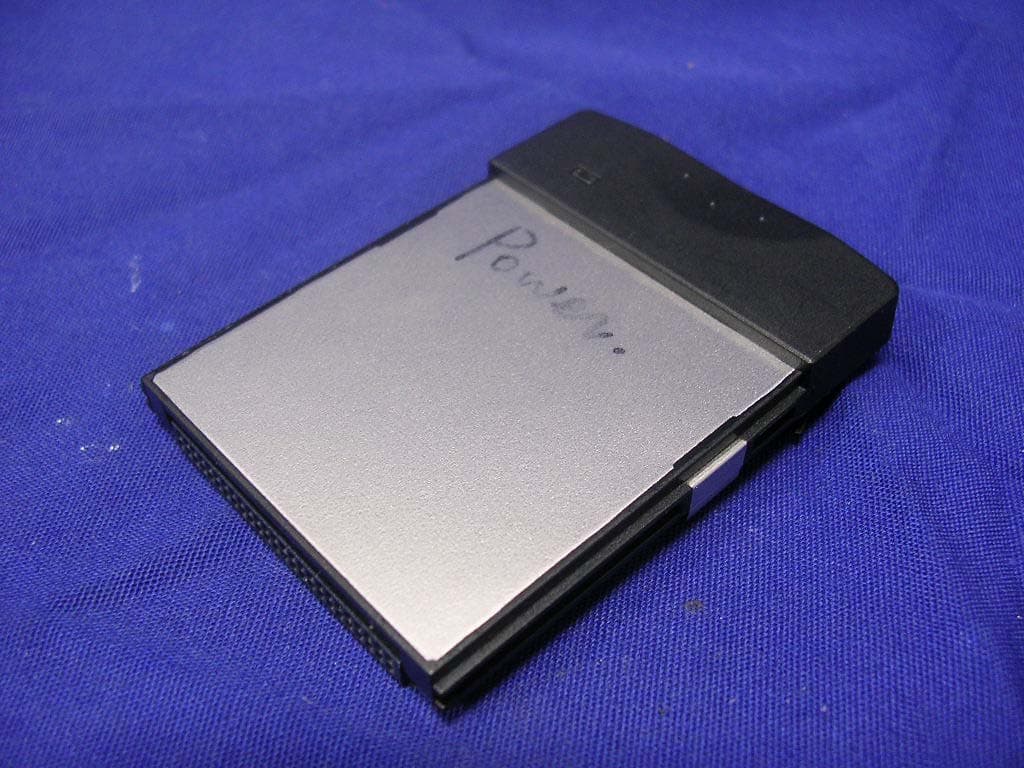
T39SLC-10200
Oct 04, 2006RFID CF Type Reader
Equipment Class
DXX - Part 15 Low Power Communication Device Transmitter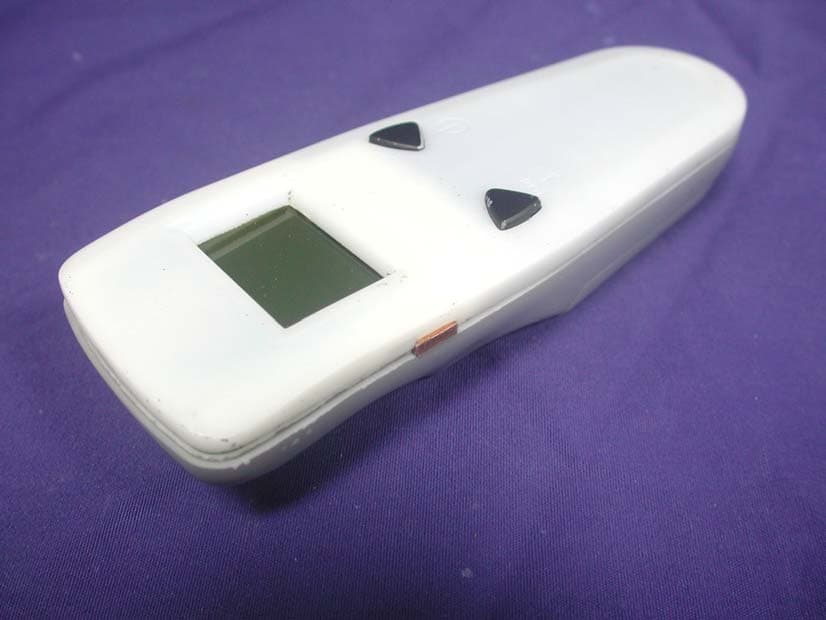
T39SLH10200
May 22, 2006RFID Hand Held Reader
Equipment Class
DSS - Part 15 Spread Spectrum Transmitter