T39SLH10200RFID Hand Held Reader
Sunlit System Technology Corp.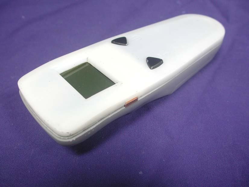
Click to zoom
Application Details
- Equipment Class
- DSS - Part 15 Spread Spectrum Transmitter
- Date of Grant
- May 22, 2006
- Application Purpose
- Original Equipment
- Date of Application
- May 22, 2006
- Equipment Note
- RFID Hand Held Reader
- Frequency Range
- 2402.00000000 - 2477.00000000
- Country
- Taiwan
Documents & Files
Document Text
Text extracted from the exhibit documents filed with the FCC. Open a document above to read the original.
Users Manual
RFID (μ-Chip) Handheld Reader User Manual Ver. 1.0 Sunlit System Technology Corp., 2006.03.01 1.Hardware 1.1 Reader Outlook (unit: mm) 1: Graphic mode LCD Screen 2: Power Button 3: Scan key 4: Battery Set 1.2 Specification 1.2.1 FSTN LCD Module: 1.3 inch screen,Graphic mode,101×67 dot, 37.5×31.6 (mm) 1.2.2 Power Button 1.2.3 Scan Key 1.2.4 Warning signal by built-in buzzer when fail in reading. 1.2.5 Size AA batteries *3(only Alkaline or Ni-MH Battery) 1.2.6 Reading Distance: 2~4cm for Bottle Label,5~7 cm for PVC 1 2 3 4 Card 1.2.7 Working Temp: up to 50°C 1.2.8 Storage Temp: up to 80°C 1.2.9 Power saving by automatically shut-down 1.3 Module/Antenna Specification 1.3.1 Voltage: DC 2.4 ~ 5V 1.3.2 Power Consumption: Standby: With LED Backlight 70 ~ 80 mA @4.0V Without LED Backlight 20 ~ 30 mA @4.0V Scanning: 130 ~ 150mA @4.0V (Average) 1.3.3 Frequency: 2.40 ~ 2.4835 GHz 1.3.4 Impedance: 50 ohm 1.3.5 Antenna Gain: 0dBi 1.3.6 Radiation: Direction 1.3.7 Polarization: Semi Circular 1.3.8 Beam Angle Degree: 90° 1.3.9 Antenna Connector: PC board on-board using T/R line 1.3.10 Scanning frequency: 100 ms with 14ms PA turn-on time 1.3.11 RF output power: 250mW +/-10mW 2.Operation: 2.1 Continuously press Power Button with 3 seconds, reader will self-test F/W and then show out ”金門高梁酒防僞判讀機及F/W版 本” on screen with 3 seconds. Later on reader will stay at ready mode with ”按掃瞄鍵掃瞄防偽標籤” on LCD screen. 2.2 Reader will turn off LCD backlight when no action during 7 seconds, in order to save power. 2.3 Reader will automatically turn off when no action after 180 seconds. 2.4 When reader automatically shuts off, LCD screen will display ”關機 中”,user can press Scanning Key to back to ready mode. 2.5 Continuously press Scanning Key to read tag,LCD screen will display ” 掃描中...” at the same time. If no tag detected, LCD screen will display ”無法偵測標籤 請重試一次” for 7 seconds and buzzer alarms 3 times. 2.6 When Reader successfully detected legal tag, LCD screen will display 10 digits number for 7 seconds. 2.7 When reader detects an illegal tag, LCD screen will display ”警告! 偵測到不合法標籤” for 7 seconds with3 alarms. 2.8 Press Power Button continuously for 3 seconds to turn-off reader. 2.9 Battery Power Status on screen. FEDERAL COMMUNICATIONS COMMISSION INTERFERENCE STATEMENT This equipment has been tested and found to comply with the limits for a Class B digital device, pursuant to Part 15 of the FCC Rules. These limits are designed to provide reasonable protection against harmful interference in a residential installation. This equipment generates, uses and can radiate radio frequency energy and, if not installed and used in accordance with the instructions, may cause harmful interference to radio communications. However, there is no guarantee that interference will not occur in a particular installation. If this equipment does cause harmful interference to radio or television reception, which can be determined by turning the equipment off and on, the user is encouraged to try to correct the interference by one or more of the following measures: – Reorient or relocate the receiving antenna. – Increase the separation between the equipment and receiver. – Connect the equipment into an outlet on a circuit different from that to which the receiver is connected. – Consult the dealer or an experienced radio/TV technician for help. CAUTION: Any changes or modifications not expressly approved by the party responsible for compliance could void the user's authority to operate the equipment. This device complies with Part 15 of the FCC Rules. Operation is subject to the following two conditions: (1) This device may not cause harmful interference and (2) This device must accept any interference received, including interference that may cause undesired operation. FCC RF Radiation Exposure Statement This equipment complies with FCC RF radiation exposure limits set forth for an uncontrolled environment. This equipment should be installed and operated with This equipment must not be co-located or operating in conjunction with a minimum distance of 20cm between the radiator and your body. any other antenna or transmitter.
Cover Letter(s)
RF_160, Issue 01 Declaration of Authorization We Name: Sunlit System Technology Corp. Address: 8F NO19 LAND120 SEC1 Neihu Rd. Taipei Taiwan 114,R.O.C. City: Taipei................................................................ Country: Taiwan ................................................................... Declare that: Name: QuieTek Corp. Address: Fl.2, No.345, Xin-hu 2 nd Rd., Nei-hu District City: Taipei Country Taiwan is authorized to apply for Certification of the following product(s): Product description: RFID Hand Held Reader............................ Type designation: SLH-10200........................................... Trademark: ................ on our behalf. Date: ...2006/5/12................. City: ...Taipei.............. Name: ...Eric Chang.............. Signature:
External Photos
Report No.: 063L094-RF-US-P06V01 Page : 1 of 6 Version:1.0 Attachment 2 : EUT Detailed Photographs (1) EUT Photo (2) EUT Photo
ID Label/Location Info
Sunlit System Technology Corp. FCC ID.: T39SLH10200 8F., No. 19, Land 120, Sec. 1, Neihu Rd, Taipei Taiwan 114, R.O.C..Tel : 886-2-6600-6351#152 FCC ID AND DoC Label The FCC ID and DoC Label will be placed on the equipment as shown in the photograph below.
ID Label/Location Info
Sunlit System Technology Corp. FCC ID.: T39SLH10200 8F., No. 19, Land 120, Sec. 1, Neihu Rd, Taipei Taiwan 114, R.O.C..Tel : 886-2-6600-6351#152 FCC ID AND DoC Label The FCC ID and DoC Label will be placed on the equipment as shown in the photograph below.
Internal Photos
Report No.: 063L094-RF-US-P06V01 Page : 2 of 6 Version:1.0 (3) EUT Photo (4) EUT Photo Report No.: 063L094-RF-US-P06V01 Page : 3 of 6 Version:1.0 (5) EUT Photo (6) EUT Photo Report No.: 063L094-RF-US-P06V01 Page : 4 of 6 Version:1.0 (7) EUT Photo (8) EUT Photo Report No.: 063L094-RF-US-P06V01 Page : 5 of 6 Version:1.0 (9) EUT Photo (10) EUT Photo Report No.: 063L094-RF-US-P06V01 Page : 6 of 6 Version:1.0 (11) EUT Photo
RF Exposure Info
Report No. 063L094-RF-US-P06V01 Page: 1 of 3 Version: 1.0 RF Exposure Evaluation declaration Product Name : RFID Hand Held Reader Model No. : SLH-10200 FCC ID T39SLH10200 Applicant : Sunlit SystemTechnology Corp. Address : 8F., No. 19, Land 120, Sec. 1, Neihu Rd., Taipei 114, Taiwan, R.O.C. Date of Receipt : March. 15, 2006 Date of Declaration: March. 31, 2006 Report No. : 063L094-RF-US-P06V01 The declaration results relate only to the samples calculated. The declaration shall not be reproduced except in full without the written approval of QuieTek Corporation. This report must not be used to claim product endorsement by NVLAP any agency of the U.S. Government Report No. 063L094-RF-US-P06V01 Page: 2 of 3 Version: 1.0 1. RF Exposure Evaluation 1.1. Limits According to FCC 1.1310: The criteria listed in the following table shall be used to evaluate the environment impact of human exposure to radio frequency (RF) radiation as specified in 1.1307(b) LIMITS FOR MAXIMUM PERMISSIBLE EXPOSURE (MPE) Frequency Range (MHz) Electric Field Strength (V/m) Magnetic Field Strength (A/m) Power Density (mW/cm 2 ) Average Time (Minutes) (A) Limits for Occupational/ Control Exposures 300-1500 -- -- F/300 6 1500-100,000 -- -- 5 6 (B) Limits for General Population/ Uncontrolled Exposures 300-1500 -- -- F/1500 6 1500-100,000 -- -- 1 30 F= Frequency in MHz Friis Formula Friis transmission formula: Pd = (Pout*G)/(4*pi*r 2 ) Where Pd = power density in mW/cm 2 Pout = output power to antenna in mW G = gain of antenna in linear scale Pi = 3.1416 R = distance between observation point and center of the radiator in cm Pd id the limit of MPE, 1 mW/cm 2 . If we know the maximum gain of the antenna and the total power input to the antenna, through the calculation, we will know the distance r where the MPE limit is reached. 1.2. Test Procedure Software provided by client enabled the EUT to transmit and receive data at lowest, middle and highest channel individually. The temperature and related humidity: 18°Cand 78% RH. Report No. 063L094-RF-US-P06V01 Page: 3 of 3 Version: 1.0 1.3. Test Result of RF Exposure Evaluation Product : RFID Hand Held Reader Test Item : RF Exposure Evaluation Test Site : CTR1 Antenna Gain Antenna Gain: The maximum Gain measured in fully anechoic chamber is 0dBi in logarithm scale. Output Power Into Antenna & RF Exposure Evaluation Distance (0dBi): Channel Frequency (MHz) Output Power to Antenna (mW) Power Density at R = 20 cm (mW/cm2) 1 2402.00 360.5786 0.0717 6 2440.00 326.5878 0.0650 11 2477.00 361.4099 0.0719 The distance r (4 th column) calculated from the Fries transmission formula is far shorter than 20 cm separation requirement.
Test Report
Report No. 063L094-RF-US-P06V01 Page: 1 of 48 Version:1.0 Test Report Product Name : RFID Hand Held Reader Model No. : SLH-10200 FCC ID. : T39SLH10200 Applicant : Sunlit SystemTechnology Corp. Address : 8F., No. 19, Land 120, Sec. 1, Neihu Rd., Taipei 114, Taiwan R.O.C. Date of Receipt : March 15, 2006 Issued Date : March 31, 2006 Report No. : 063L094-RF-US-P06V01 The Test Results relate only to the samples tested. The test report shall not be reproduced except in full without the written approval of QuieTek Corporation. This report must not be used to claim product endorsement by NVLAP any agency of the U.S. Government Report No. 063L094-RF-US-P06V01 Page: 2 of 48 Version:1.0 Test Report Certification Issued Date: March 31, 2006 Report No.: 063L094-RF-US-P06V01 Product Name : RFID Hand Held Reader Applicant : Sunlit SystemTechnology Corp. Address : 8F., No. 19, Land 120, Sec. 1, Neihu Rd., Taipei 114, Taiwan R.O.C. Manufacturer : Sunlit SystemTechnology Corp. Model No. : SLH-10200 FCC ID. : T39SLH10200 Rated Voltage : AC 120V/60Hz Working Voltage : DC 4.5V Trade Name : Applicable Standard : FCC CFR Title 47 Part 15 Subpart C: 2005 ANSI C63.4: 2003 CISPR 22: 2005 Test Result : Complied The Test Results relate only to the samples tested. The test report shall not be reproduced except in full without the written approval of QuieTek Corporation. This report must not be used to claim product endorsement by NVLAP any agency of the U.S. Government Documented By : ( Genie Chang ) Tested By : ( Tom Hsieh ) Approved By : ( Gene Chang ) 0914 Accredited by NIST (NVLAP) NVLAP Lab Code: 200533-0 Report No. 063L094-RF-US-P06V01 Page: 3 of 48 Version:1.0 TABLE OF CONTENTS Description Page 1. GENERAL INFORMATION ...............................................................................................................5 1.1. EUT Description......................................................................................................................................5 1.2. Operational Description...........................................................................................................................6 1.3. Tested System Details..............................................................................................................................7 1.4. Configuration of Tested System ..............................................................................................................7 1.5. EUT Exercise Software ...........................................................................................................................8 1.6. Test Facility .............................................................................................................................................9 2. CONDUCTED EMISSION ................................................................................................................10 2.1. Test Equipment ......................................................................................................................................10 2.2. Test Setup ..............................................................................................................................................10 2.3. Limits.....................................................................................................................................................11 2.4. Test Procedure .......................................................................................................................................11 2.5. Uncertainty ............................................................................................................................................11 2.6. Test Result of Conducted Emission .......................................................................................................12 3. PEAK POWER OUTPUT ..................................................................................................................13 3.1. Test Equipment ......................................................................................................................................13 3.2. Test Setup ..............................................................................................................................................13 3.3. Limit .................................................................................................................13 3.4. Uncertainty ............................................................................................................................................13 3.5. Test Result of Peak Power Output .........................................................................................................14 4. RADIATED EMISSION .....................................................................................................................15 4.1. Test Equipment ......................................................................................................................................15 4.2. Test Setup ..............................................................................................................................................16 4.3. Limits.....................................................................................................................................................16 4.4. Test Procedure .......................................................................................................................................17 4.5. Uncertainty ............................................................................................................................................17 4.6. Test Result of Radiated Emission ..........................................................................................................18 5. BAND EDGE .......................................................................................................................................24 5.1. Test Equipment ........…
Text truncated - open the document above for the full version.
Test Setup Photos
Report No.: 063L094-RF-US-P06V01 Page : 1 of 2 Version:1.0 Attachment 1: EUT Test Setup Photographs Front View of Radiated Test Back View of Radiated Test Report No.: 063L094-RF-US-P06V01 Page : 2 of 2 Version:1.0 Front View of Radiated Test (Horn) Back View of Radiated Test (Horn)
Contact Information
Applicant
Vincent Su
Technical Contact
QuieTek CorporationGeorge Chen
[email protected]+886-2-8601-3788
No. 5-22, Ruei-Shu Valley,Ruei-Ping Tsuen, · Lin-Kou Shiang,Taipei, · Taiwan
Test Firm
DEKRA Testing and Certification Co., Ltd.Sky Hsu
Technical Specifications
| # | Rule Parts | Frequency Range | Power Output |
|---|---|---|---|
| 1 | 15C | 2.40 GHz - 2.48 GHz | 361.00 mW |
Other Applications from Sunlit System Technology Corp.
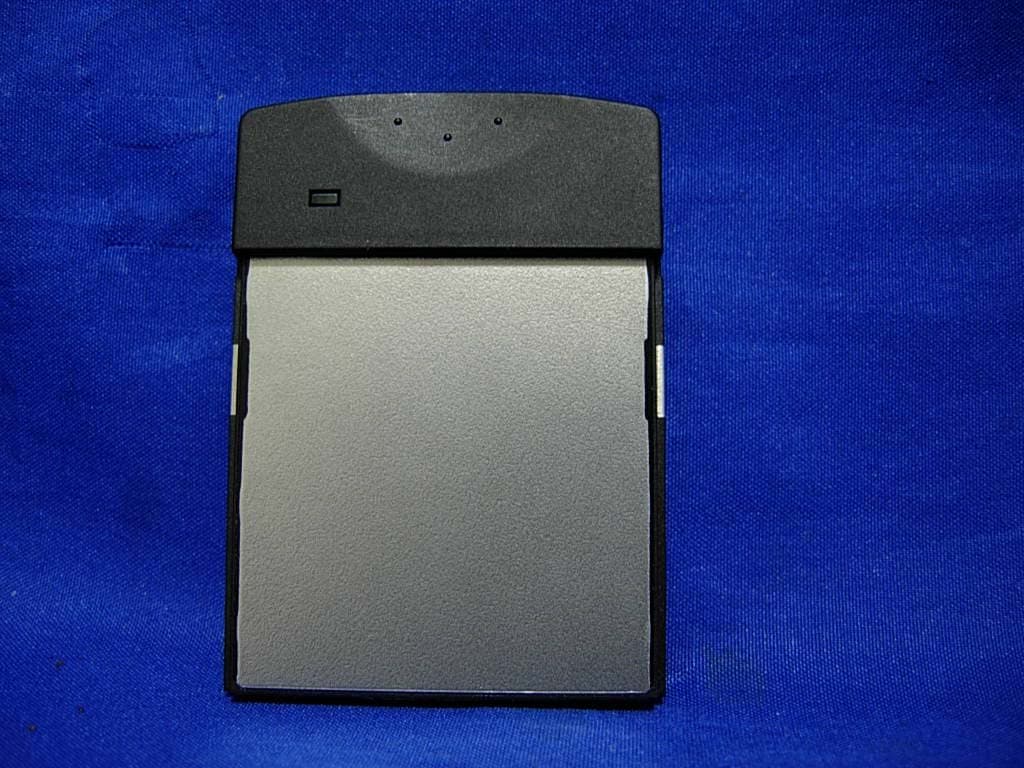
T39SLC11100
May 28, 2007RFID CF Type Reader
Equipment Class
DSS - Part 15 Spread Spectrum Transmitter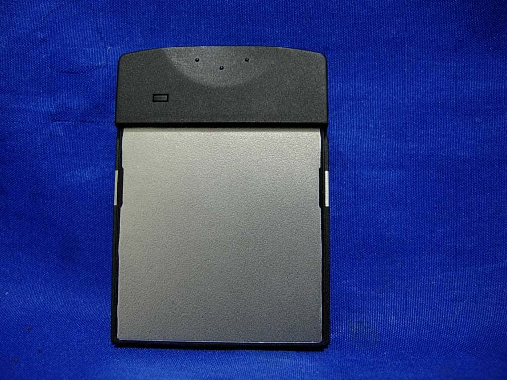
T39SLC10100
Apr 29, 2007RFID CF TYPE READER
Equipment Class
DSS - Part 15 Spread Spectrum Transmitter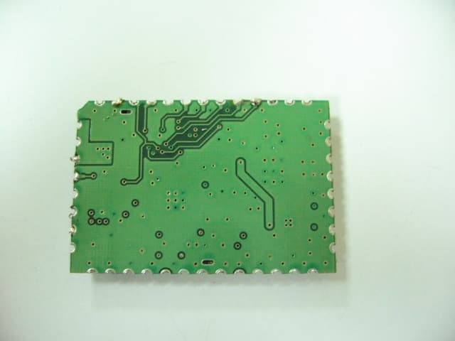
T39SLF10100
Feb 04, 2007RF Module v4.0
Equipment Class
DSS - Part 15 Spread Spectrum Transmitter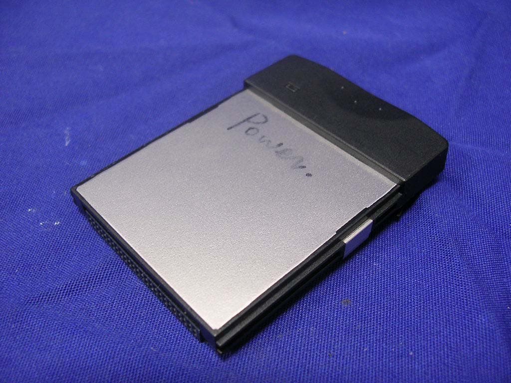
T39SLC-10200
Oct 04, 2006RFID CF Type Reader
Equipment Class
DXX - Part 15 Low Power Communication Device Transmitter