T39SLF10100RF Module v4.0
Sunlit System Technology Corp.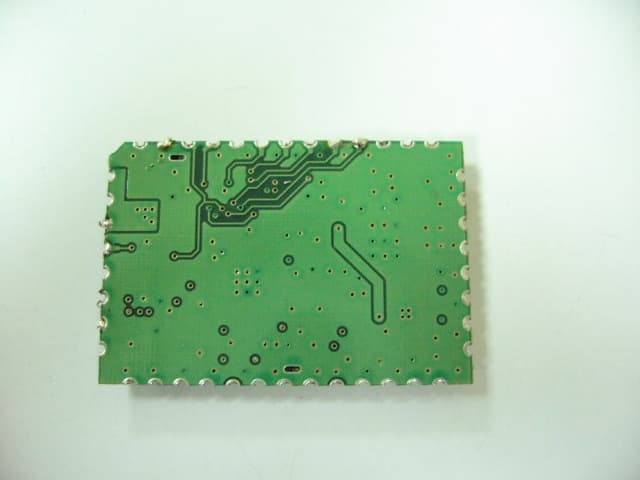
Click to zoom
Application Details
- Equipment Class
- DSS - Part 15 Spread Spectrum Transmitter
- Date of Grant
- Feb 04, 2007
- Application Purpose
- Original Equipment
- Date of Application
- Feb 04, 2007
- Equipment Note
- RF Module v4.0
- Frequency Range
- 2402.00000000 - 2477.00000000
- Country
- Taiwan
Documents & Files
Document Text
Text extracted from the exhibit documents filed with the FCC. Open a document above to read the original.
Users Manual
RFID RF Module User’s Guide Model Number: SLF-10100 Model Name: RF Module v4.0 Edition version: 1.0 Date: 2006.11.28 Regulatory Approvals FCC Statement This equipment has been tested and found to comply with the limits for a Class B digital device, pursuant to Part 15 of the FCC Rules. These limits are designed to provide reasonable protection against harmful interference in a residential installation. This equipment generates, uses and can radiate radio frequency energy and, if not installed and used in accordance with the instructions, may cause harmful interference to radio communica- tions. However, there is no guarantee that interference will not occur in a particular installation. If this equipment does cause harmful interference to radio or television reception, which can be determined by turning the equipment off and on, the user is encouraged to try to correct the interference by one of the following measures: Reorient or relocate the receiving antenna. Increase the separation between the equipment and receiver. Connect the equipment into an outlet on a circuit different from that to which the receiver is connected. Consult the dealer or an experienced radio/TV technician for help. To assure continued compliance, any changes or modifications not expressly approved by the party responsible for compliance could void the user's authority to operate this equipment. (Example - use only shielded interface cables when connecting to computer or peripheral devices). FCC Radiation Exposure Statement This equipment complies with FCC RF radiation exposure limits set forth for an uncontrolled environment. This equipment should be installed and operated with a minimum distance of 20 centimeters between the radiator and your body. This device complies with Part 15 of the FCC Rules. Operation is subject to the following two conditions: (1) This device may not cause harmful interference, and (2) This device must accept any interference received, including interference that may cause undesired operation. This transmitter must not be co-located or operating in conjunction with any other antenna or transmitter. The antennas used for this transmitter must be installed to provide a separation distance of at least 20 cm from all persons and must not be co-located or operating in conjunction with any other antenna or transmitter. Channel The Wireless Channel sets the radio frequency used for communication. Access Points use a fixed Channel. You can select the Channel used. This allows you to choose a Channel which provides the least interference and best performance. In the USA and Canada, 11 channel are available. If using multiple Access Points, it is better if adjacent Access Points use different Channels to reduce interference. In "Infrastructure" mode, Wireless Stations normally scan all Channels, looking for an Access Point. If more than one Access Point can be used, the one with the strongest signal is used. (This can only happen within an ESS.) If using "Ad-hoc" mode (no Access Point), all Wireless stations should be set to use the same Channel. However, most Wireless stations will still scan all Channels to see if there is an existing "Ad-hoc" group they can join. -2 Index No. Item Page 1 Hardware 03 2 Software Operation 06 3 How to Contact Us 17 4 5 6 7 Notice: In order to avoid misuse or any unexpected damage, please read this guide first. This device complies with Part 15 of FCC Rules. Operation is subject to the following two conditions: (1)This device may not cause harmful interference ,and (2)This device must accept any interference received, including interference that may cause undesired operation -3 1. Hardware (1) Pin Description Pin No. Pin Name Pin Function 1,2,5,11~25, 27~29,31~38 GND Ground 3 LED LED Display 4,6,7,8,26,30 NC No Connect 9 TXD Transmitter Output For The Serial Port 10 RXD Receiver Input For The Serial Port 39 PEN Power Supply Enable 40~42 VCC Power Supply -4 (2) Package Outline Figure: Package Outline – 42 Pin 37mm x 25mm x 3.6mm Surface Mount Module -5 (3) Specification Power Supply Voltage DC 4.5V ~ 6.5V 500mA RF Output Power 100 mW (Contact) Trigger Mode Active & Passive LED Lamp Power on & Read TAG(Pin Output) Interface RS-232(TTL Level) Pin Output 44 Pin PCB Layer 4 Layer Outer Antenna U.FL Connector Operation Temperature 0 C ~ 45 C Storage Temperature 0 C ~ 60 C Frequency Range 2.40 GHz ~ 2.483 GHz Environment Requirement Storing Humidity 5-85%RH(no condensation allowed) Dimensions 37 x 25 x 2.8 (mm) -6 2. Software Operation (1) Environment (2) Operation Requirement Item Condition PC CPU≧ Intel Pentium III RAM≧128 MB CD/DVD-ROM Operation System Windows XP Windows 2000 SP4 Antenna Load board RS232 Interface DC Power RFID Module -7 (3) Software introduction This software program can build a database include TAG ID、TAG information and picture.It can be use to demo for material management、access control... etc. Software contents Item Description Development tool Microsoft Visual Studio 2005 Traditional Edition DemoDTR.exe Main program Sunlitrfid.dll Dynamic Link Library file Database.txt ID database file File contents PIC [Folder] A picture file includes different pictures which correlated with each individual ID System requirement Item Condition Personal Computer CPU≧ Intel Pentium III RAM≧128 MB CD/DVD-ROM Operation System Windows XP Windows 2000 SP4 -8 Main Program Window Item Description Item Description Port Name Show Device Comport Save Save registered database Open/Close Open & Close Device Comport Clear Clear text of Message window Find Finding Comport when device add Exit Exit program Operation Mode Select Active or Passive Operation mode Tag Data Base List Display registered database Mute Disable & Enable reading sound Tag Information Edit information about Tag ID Read Tag Trigger reader to scan tag Read Tag ID Display Tag ID when Tag be read. Delete Delete database Message Display status of reader Picture Select picture correct with ID -9 Block Diagram…
Text truncated - open the document above for the full version.
Block Diagram
11 A A RF ASIC Baluns Attenuator Network LPF Network Power Amplifier LPF Circulators LPF 13MHZ Antenna Connector Regulator MCU Power Interfact PAD PA Power ControlOn/Off Power input PAD Attenuator Network
Cover Letter(s)
Request for modular approval FCC ID: T39SLF10100 To Whom It May Concern, The Sunlit System Technology Corp. Product RF Module v4.0, Model SLF10100 is seeking FCC authorization as a module transmitter. The requirement of the FCC Public notice DA00-1407 are met. The following requirement are fulfilled: 1. The module transmitter must have its own shielding. The radio portion of the module is contained in its own RF shielding. See the external photos. 2. The Module transmitter must have buffered modulation / data inputs. The module has a memory management unit inside of the IC It buffers the data inputs from UART and MiniPCI terminal. 3. The module transmitter must have its own power supply regulation. The IC contains an own voltage regulation. In case of change in the supply voltage VCC (for example cause by temperature changes or other effect), The internal voltage will be stabilized. 4. The module transmitter must comply with the antenna requirement of Section 15. 203 and 15. 204c. The transmitter shall only be used with the tested integral antenna or with an antenna that has less antenna gain. Requirement for the use of external antennas are specified in the antenna information exhibit. 5. The module transmitter must be tested in a stand-alone configuration. The EUT was tested in a stand-alone configuration. The module was fixed in test / programming board during the test. See also the test report and test setup photos. 6. The module transmitter must be labeled with its own FCC ID number. The EUT will be labeled with its own FCC ID number. If the module is installed inside of an end-product, the label will not be visible. 7. The module transmitter must comply with any rule or operating requirement applicable to the transmitter and the manufacturer must provide adequate instruction along with the module to explain any such requirements. The EUT is compliant with all applicable FCC reles. Detail instruction are given in the Users Guide. 8. The module transmitter must comply with any applicable RF exposure requirement. The transmitter herein was tested with the antenna that is integrated on the radio module. Compliance to RF exposure requirement for this antenna is included within this application for approval. Appropriate warning statement will be placed with each end product user information based on the results of the RF exposure data filed with this application. OEM Resellers will be advised to include a similar statement to inform the users of any requirement for RF safety. Please contact us if you have any addition question. Best Regards, Nick Hsu Sunlit System Technology Corp. Technology Division R&D Department Manager
External Photos
Project No.: 0612062 Page 2 of 5 Neutron Engineering Inc. 0612062 061206 2 Project No.: 0612062 Page 3 of 5 Neutron Engineering Inc. 0612062 061206 2
Internal Photos
Project No.: 0612062 Page 4 of 5 Neutron Engineering Inc. 0612062 061206 2 Project No.: 0612062 Page 5 of 5 Neutron Engineering Inc. 0612062
RF Exposure Info
1.1. Test Result of RF Exposure Evaluation . Product: RF Module v40. . Test Item: RF Exposure Evaluation Data . Test site: OATSI-SD . Test Mode: Normal Operation 1.1.1. Antenna Gain The maximum Gain is 9.26 dBi. 1.1.2. EUT Operation condition Software provided by client enabled the EUT to transmit and receive data at lowest, middle and highest channel individually. 1.1.3. Output Power into Antenna & RF Exposure Evaluation Distance Modulation Standard: Bluetooth Test Date: Jan. 13, 2006 Temperature: 27 °C Humidity: 60% Channel Channel Frequency (MHz) Output Power to Antenna (dBm) Power Density (S) (mW/cm 2 ) 00 2402 11.14 0.021825 38 2440 19.39 0.145865 77 2477 9.25 0.014124 The MPE is calculated as 0.145865 mW / cm 2 < limit 1 mW / cm 2 . So, RF exposure limit warning or SAR test are not required. For 2402-2477 MHz, the EUT will only be used with a separation of 20cm or greater between the antenna and nearby persons and can therefore be considered a mobile transmitter per 47CFR2.1091 (b). The RF Exposure Information page from the manual is included here for reference.
Test Report
Report No.: NEI-FCCP-1-0612062 Page 2 of 104 Neutron Engineering Inc. Declaration Neutron represents to the client that testing is done in accordance with standard procedures as applicable and that test instruments used has been calibrated with the standards traceable to National Measurement Laboratory (NML) of R.O.C., or National Institute of Standards and Technology (NIST) of U.S.A. Neutron's reports apply only to the specific samples tested under conditions. It is manufacture’s responsibility to ensure that additional production units of this model are manufactured with the identical electrical and mechanical components. Neutron shall have no liability for any declarations, inferences o r generalizations drawn by the client or others from Neutron issued reports. Neutron’s reports must not be used by the client to claim product endorsement by the authorities or any agency of the Government. This report is the confidential property of the client. As a mutual protection to the clients, the public and Neutron-self, extracts from the test report shall not be reproduced except in full with Neutron’s authorized written approval. Neutron’s laboratory quality assurance procedures are in compliance with the ISO Guide 17025 requirements, and accredited by the conformity assessment authorities listed in this test report. Limitation For the use of the authority's logo is limited unless the Test Standard(s)/Scope(s)/Item(s) mentioned in this test report is (are) included in the conformity assessment authorities acceptance respective. Report No.: NEI-FCCP-1-0612062 Page 3 of 104 Neutron Engineering Inc. Table of Contents Page 1 . CERTIFICATION 6 2 . SUMMARY OF TEST RESULTS 7 2.1 TEST FACILITY 8 2.2 MEASUREMENT UNCERTAINTY 8 3 . GENERAL INFORMATION 9 3.1 GENERAL DESCRIPTION OF EUT 9 3.1.1 Table of Carrier Frequencies 10 3.1.2 Table for Filed Antenna 10 3.2 DESCRIPTION OF TEST MODES 11 3.3 Table of Parameters of Text Software Setting 11 3.4 BLOCK DIGRAM SHOWING THE CONFIGURATION OF SYSTEM TESTED 12 3.5 DESCRIPTION OF SUPPORT UNITS 13 4 . EMC EMISSION TEST 14 4.1 CONDUCTED EMISSION MEASUREMENT 14 4.1.1 POWER LINE CONDUCTED EMISSION LIMITS 14 4.1.2 MEASUREMENT INSTRUMENTS LIST AND SETTING 14 4.1.3 TEST PROCEDURE 15 4.1.4 DEVIATION FROM TEST STANDARD 15 4.1.5 TEST SETUP 15 4.1.6 EUT OPERATING CONDITIONS 16 4.1.7 TEST RESULTS 17 4.2 RADIATED EMISSION MEASUREMENT 23 4.2.1 RADIATED EMISSION LIMITS 23 4.2.2 MEASUREMENT INSTRUMENTS LIST AND SETTING 24 4.2.3 TEST PROCEDURE 25 4.2.4 DEVIATION FROM TEST STANDARD 25 4.2.5 TEST SETUP 26 4.2.6 EUT OPERATING CONDITIONS 26 4.2.7 TEST RESULTS-Between 9kHz and 30MHz 27 4.2.8 TEST RESULTS-Between 30MHz and 1000MHz 30 4.2.9 TEST RESULTS-Above 1000MHz~10th Harmonic 36 5 . 20dB BANDWITH TEST and Channel Separation Measurement 72 5.1 APPLIED PROCEDURES / LIMIT 72 5.1.1 MEASUREMENT INSTRUMENTS LIST AND SETTING 72 5.1.2 TEST PROCEDURE 72 5.1.3 DEVIATION FROM STANDARD 72 Report No.: NEI-FCCP-1-0612062 Page 4 of 104 Neutron Engineering Inc. Table of Contents Page 5.1.4 TEST SETUP 72 5.1.5 EUT OPERATION CONDITIONS 73 5.1.6 TEST RESULTS 74 6 . Number of Hopping Channel 78 6.1 APPLIED PROCEDURES / LIMIT 78 6.1.1 MEASUREMENT INSTRUMENTS LIST AND SETTING 78 6.1.2 TEST PROCEDURE 78 6.1.3 DEVIATION FROM STANDARD 78 6.1.4 TEST SETUP 78 6.1.5 EUT OPERATION CONDITIONS 78 6.1.6 TEST RESULTS 79 7 . PEAK OUTPUT POWER TEST 81 7.1 APPLIED PROCEDURES / LIMIT 81 7.1.1 MEASUREMENT INSTRUMENTS LIST 81 7.1.2 TEST PROCEDURE 81 7.1.3 DEVIATION FROM STANDARD 81 7.1.4 TEST SETUP 81 7.1.5 EUT OPERATION CONDITIONS 81 7.1.6 TEST RESULTS 82 8 . ANTENNA CONDUCTED SPURIOUS EMISSION 84 8.1 APPLIED PROCEDURES / LIMIT 84 8.1.1 MEASUREMENT INSTRUMENTS LIST AND SETTING 84 8.1.2 TEST PROCEDURE 84 8.1.3 DEVIATION FROM STANDARD 84 8.1.4 TEST SETUP 85 8.1.5 EUT OPERATION CONDITIONS 85 8.1.6 TEST RESULTS 86 9 . Maximum Permissible Exposure (MPE) 88 9.1 APPLIED PROCEDURES / LIMIT 88 9.1.1 MEASUREMENT INSTRUMENTS LIST 88 9.1.2 MPE CALCULATION METHOD 89 9.1.3 DEVIATION FROM STANDARD 89 9.1.4 TEST SETUP 89 9.1.5 EUT OPERATION CONDITIONS 89 9.1.6 TEST RESULTS 90 10 . DWELL TIME 91 10.1 APPLIED PROCEDURES / LIMIT 91 10.1.1 MEASUREMENT INSTRUMENTS LIST 91 10.1.2 TEST PROCEDURE 91 Report No.: NEI-FCCP-1-0612062 Page 5 of 104 Neutron Engineering Inc. Table of Contents Page 10.1.3 DEVIATION FROM STANDARD 91 10.1.4 TEST SETUP 91 10.1.5 EUT OPERATION CONDITIONS 91 10.1.6 TEST RESULTS 92 11 . EUT TEST PHOTO 96 Report No.: NEI-FCCP-1-0612062 Page 6 of 104 Neutron Engineering Inc. 1. CERTIFICATION E q u i p m e n t : RF Module v4.0 Trade Name : Model Name. : SLF-10100 A p p l i c a n t : SUNLIT System Technology Corp. Data of Test : Dec. 08, 2006 ~ Jan. 15, 2007 T e s t I t e m : ENGINEERING SAMPLE Standards : FCC Part15, Subpart C / ANCI C63.4 : 2003 The above equipment has been tested and found compliance with the requirement of the relative standards by Neutron Engineering Inc. EMC Laboratory. The test data, data evaluation, and equipment configuration contained in our test report (Ref No. NEI-FCCP-1-0612062) were obtained utilizing the test procedures, test instruments, test sites that has been accredited by the Authority of NVLAP and CNLA according to the ISO-17025 quality assessment standard and technical standard(s). Report No.: NEI-FCCP-1-0612062 Page 7 of 104 Neutron Engineering Inc. 2. SUMMARY OF TEST RESULTS Test procedures according to the technical standards: FCC Part15, Subpart C Standard Section Test Item Judgment Remark 15.207 Conducted Emission PASS 15.247 (c) Antenna conducted Spurious Emission PASS 15.247 (a)(1) Hopping Channel Separation PASS 15.247 (b)(1) Peak Output Power PASS 15.247 (c) Radiated Spurious Emission PASS 15.247 (b)(1) Number of Hopping Frequency PASS 15.247 (a)(1) Dwell Time PASS 15.205 Restricted Bands PASS 15.203 Antenna Requirement PASS 1.1307 1.1310 2.1091 2.1093 RF Exposure Compliance PASS NOTE: (1)” N/A” denotes test is not applicable in this Test Report Report No.: NEI-FCCP-1-0612062 Page…
Text truncated - open the document above for the full version.
Test Setup Photos
Report No.: NEI-FCCP-1-0612062 Page 96 of 104 Neutron Engineering Inc. 11. EUT TEST PHOTO Conducted Measurement Photos Antenna: IPX-MUR9SAXX-423(ANT1) Report No.: NEI-FCCP-1-0612062 Page 97 of 104 Neutron Engineering Inc. Conducted Measurement Photos Antenna: PA1-2450CSA (ANT2) Report No.: NEI-FCCP-1-0612062 Page 98 of 104 Neutron Engineering Inc. Conducted Measurement Photos Antenna: Dipole (ANT3) Report No.: NEI-FCCP-1-0612062 Page 99 of 104 Neutron Engineering Inc. Radiated Measurement Photos Radiated Emission Test Set-up, Frequency Between 30-1000MHz Antenna: IPX-MUR9SAXX-423(ANT1) Report No.: NEI-FCCP-1-0612062 Page 100 of 104 Neutron Engineering Inc. Radiated Measurement Photos Radiated Emission Test Set-up, Frequency Between 30-1000MHz Antenna: PA1-2450CSA (ANT2) Report No.: NEI-FCCP-1-0612062 Page 101 of 104 Neutron Engineering Inc. Radiated Measurement Photos Radiated Emission Test Set-up, Frequency Between 30-1000MHz Antenna: Dipole (ANT3) Report No.: NEI-FCCP-1-0612062 Page 102 of 104 Neutron Engineering Inc. Radiated Measurement Photos Radiated Emission Test Set-UP, Frequency Above 1000MHz Antenna: IPX-MUR9SAXX-423(ANT1) Report No.: NEI-FCCP-1-0612062 Page 103 of 104 Neutron Engineering Inc. Radiated Measurement Photos Radiated Emission Test Set-UP, Frequency Above 1000MHz Antenna: PA1-2450CSA (ANT2) Report No.: NEI-FCCP-1-0612062 Page 104 of 104 Neutron Engineering Inc. Radiated Measurement Photos Radiated Emission Test Set-UP, Frequency Above 1000MHz Antenna: Dipole (ANT3)
Contact Information
Applicant
Vincent Su
Test Firm
BTL Inc.Andy Yeh
Technical Specifications
| # | Rule Parts | Frequency Range | Power Output |
|---|---|---|---|
| 1 | 15C | 2.40 GHz - 2.48 GHz | 87.00 mW |
Other Applications from Sunlit System Technology Corp.
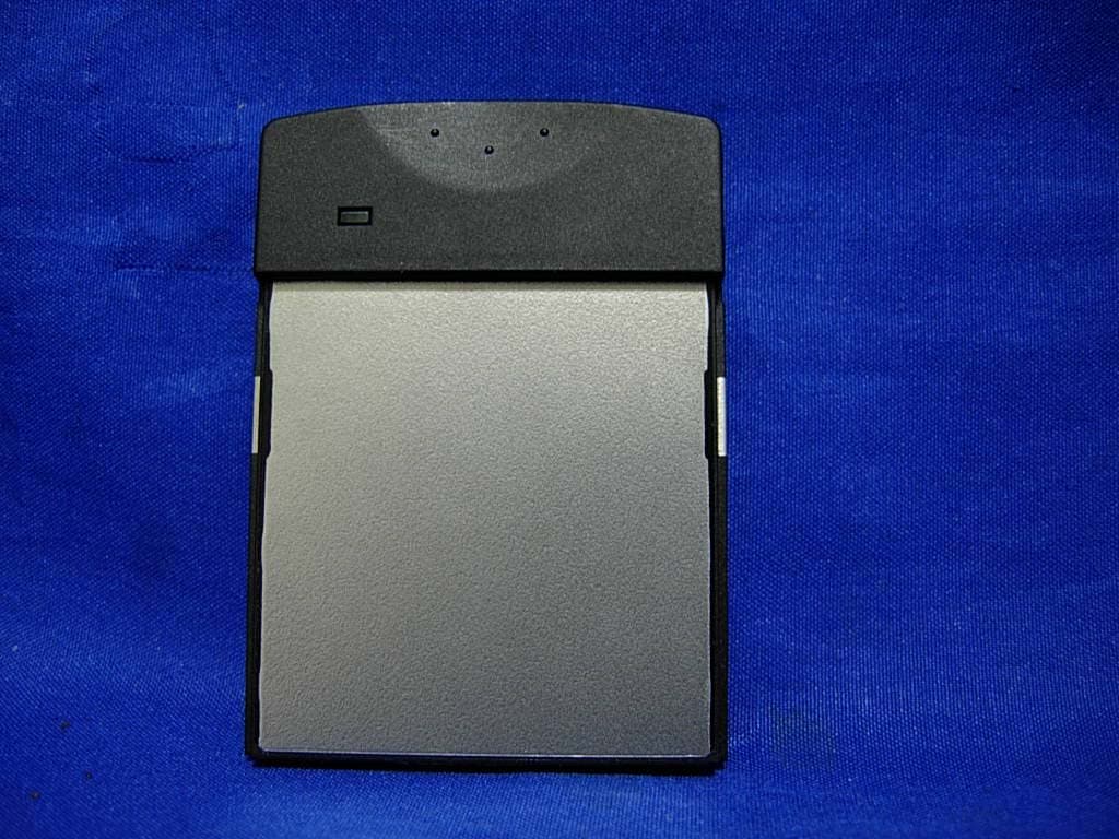
T39SLC11100
May 28, 2007RFID CF Type Reader
Equipment Class
DSS - Part 15 Spread Spectrum Transmitter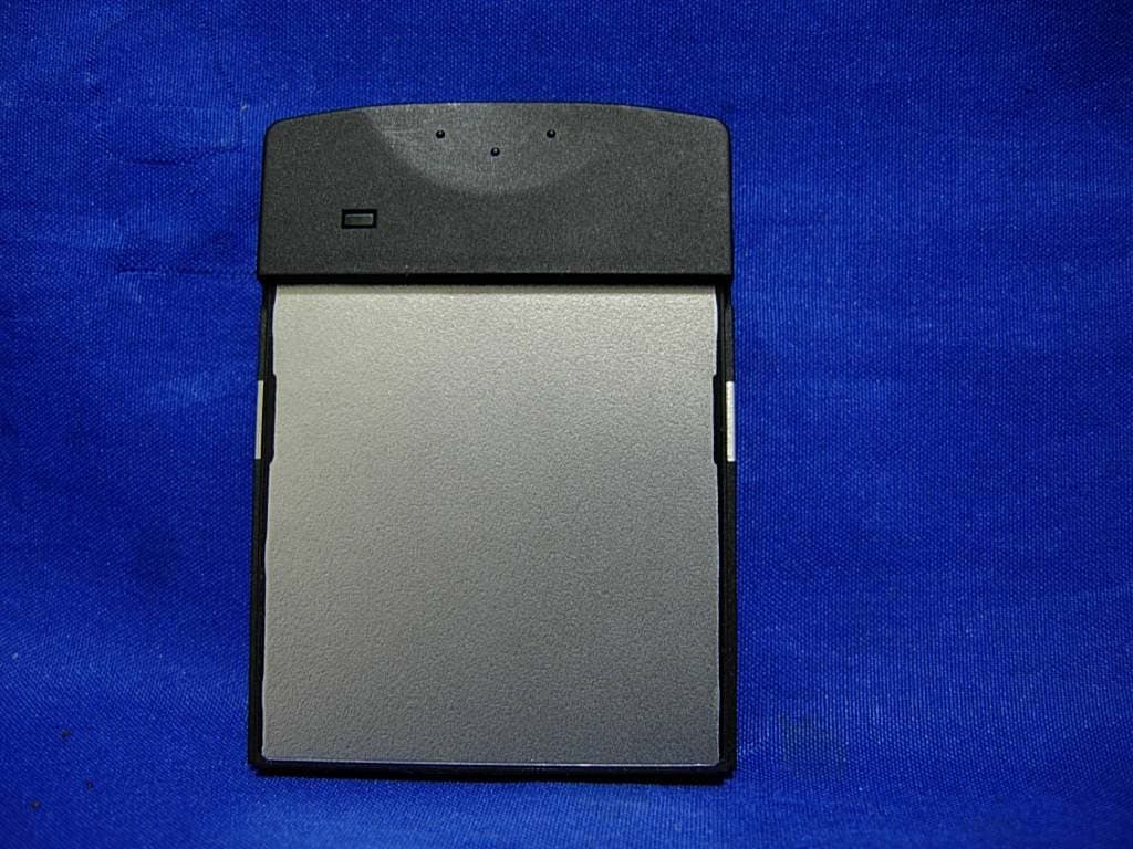
T39SLC10100
Apr 29, 2007RFID CF TYPE READER
Equipment Class
DSS - Part 15 Spread Spectrum Transmitter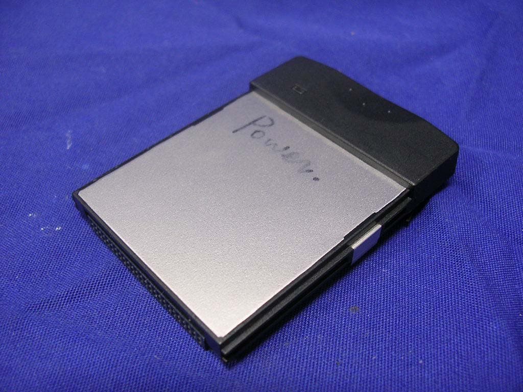
T39SLC-10200
Oct 04, 2006RFID CF Type Reader
Equipment Class
DXX - Part 15 Low Power Communication Device Transmitter
T39SLH10200
May 22, 2006RFID Hand Held Reader
Equipment Class
DSS - Part 15 Spread Spectrum Transmitter