T4FSM2112212.4 GHz Wi-Fi and BLE Wireless Gateway
Building Automation Products, Inc.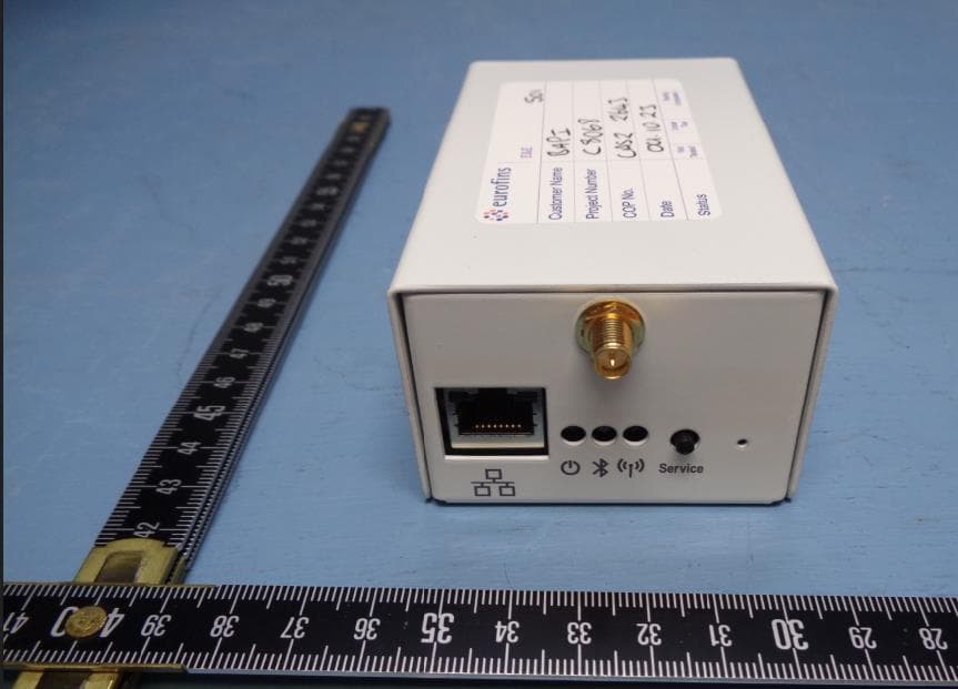
Click to zoom
Application Details
- Equipment Class
- DTS - Digital Transmission System
- Date of Grant
- Jul 10, 2024
- Application Purpose
- Original Equipment
- Date of Application
- Jul 10, 2024
- Equipment Note
- 2.4 GHz Wi-Fi and BLE Wireless Gateway
- Frequency Range
- 2402.00000000 - 2480.00000000
- Country
- United States
Documents & Files
Document Text
Text extracted from the exhibit documents filed with the FCC. Open a document above to read the original.
Users Manual
Installation & Operating Instructions Building Automation Products, Inc., 750 North Royal Avenue, Gays Mills, WI 54631 USA Tel:+1-608-735-4800 • Fax+1-608-735-4804 • E-mail:[email protected] • Web:www.bapihvac.com rev. 03/22/24 50387_Wireless_BLE_Gateway 1 of 6 Wireless Bluetooth Low Energy Gateway Power Up of the Gateway Attach the provided antennas. Power the unit by inserting the included Micro USB cable into the “Micro USB” power port or by connecting a PoE-enabled cable to the PoE Port. Note: The ethernet port does not have network capabilities at present but is only used for PoE. Upon power-up, the green “Power” LED will be blinking rapidly (on and off about twice per second). This indicates that the gateway is in SoftAP mode waiting for you to complete the connection process. If the green “Power” LED is blinking slowly (on for a second and off for a second), then the gateway will need to be reset to SoftAP mode. See “Resetting the Gateway to SoftAP Mode” on pg 3. Connecting the Gateway Use your phone, tablet or computer to follow the steps below. 1. With the gateway in SoftAP mode as described above, open up the Wi-Fi settings on your mobile device or computer and select “bapi_gateway” from the list of available networks (Fig 2). If your device asks for a password or network security key, enter “changebp”. 2. Using the same device, open a web browser and enter “10.10.0.1” into the address bar, not the search bar. The gateway’s list of available Wi-Fi Networks will come up (Fig 3). 3. Click on the desired Wi-Fi network from the “Scan List” and enter the password for that network (Fig 4). Click Connect. 4. During the connection process, the various LEDs will blink for 15 to 20 seconds. The connection is complete when the green “Power” LED is blinking slowly (on for a second, off for a second) and is the only LED on. You can now close your web browser window. (Note: If the amber “Wi-Fi” LED doesn’t go out and continues to blink, the connection has failed. See “Resetting the Gateway” on pg 3.) Powering Up and Connecting the Gateway ● Gateway provides data via MQTT to the cloud ● Each gateway supports up to 32 sensors that can be configured remotely via the gateway and BAPI’s WAM user interface BAPI’s gateway receives the data from one or more sensors and provides the data to the cloud via MQTT using your local Wi-Fi connection. Sensors can be configured remotely via the gateway and BAPI’s WAM user interface. The gateway sends a confirmation signal to each sensor upon a successful reception. If the sensor doesn’t receive this confirmation, then the sensor retains the readings in its onboard memory and transmits them once communication is re-established. Note: A WAM subscription is necessary to view sensor data and adjust sensor settings. See “WAM and the WAM Website” on pg 4. Wireless Gateway and included USB to Micro USB Cable Overview Ethernet PoE Port Green “Power” LED Blue “Bluetooth” LED Amber “Wi-Fi” LED “Service” Button Fig. 1: Gateway PoE Port and LEDs Fig. 3: Available Wi-Fi Networks Fig. 2: Gateway on Wi-Fi Network Fig. 4: Wi-Fi Network Password Continued on next page... Note: the gateway communicates with 2.4 GHz Wi-Fi and will not work on 5.0 GHz networks. Users will need to change their wifi settings to accommodate this for the gateway to connect to the Internet. Installation & Operating Instructions Building Automation Products, Inc., 750 North Royal Avenue, Gays Mills, WI 54631 USA Tel:+1-608-735-4800 • Fax+1-608-735-4804 • E-mail:[email protected] • Web:www.bapihvac.com rev. 03/22/24 50387_Wireless_BLE_Gateway 2 of 6 Wireless Bluetooth Low Energy Gateway Pairing Sensors with the Gateway 1. Select the sensor that you wish to pair to the gateway. Apply power to the sensor. See its manual for detailed instructions. 2. Press and hold the “Service” button on the gateway until the blue “Bluetooth” LED begins to flash (about 3 seconds). Then release the “Service” button to enter pairing mode. NOTE: When in pairing mode, the blue “Bluetooth” LED will continue to flash providing the user a 20 second window to pair the sensor with the gateway. 3. Press and release the “Service” button on the sensor to pair it with the gateway. When the sensor is successfully paired, the sensor will flash its green “Service” LED 3 times and the blue “Bluetooth” LED on the gateway will go out. The blue “Bluetooth” LED will then flash each time a sensor communicates with the gateway. The sensor will now appear as one of the devices for that gateway on the WAM website. Fig. 8: BAPI-Box Sensor Service Button and LED Service LED Service Button Service LED Service Button Fig. 9: BAPI-Stat “Quantum” Sensor Service Button and LED The figures above are shown for reference. Refer to the instructions document for your specific sensor for the location of the “Service” button and “Service” LED. Powering Up and Connecting the Gateway continued... 5. Pair one of your sensors with the gateway as described in the next section “Pairing Sensors with the Gateway” and then return to Step 6. At least one sensor MUST be paired with the gateway before going to the next step. 6. Reconnect your phone, tablet or computer to your original Wi-Fi or ethernet network and open the BAPI WAM website (https://wam.bapisensors.com) to register and set up your WAM account. Enter the Username and Password for your WAM subscription. (A WAM subscription is required to view your sensor data. If you do not have a subscription, contact your BAPI representative to subscribe and receive your login credentials.) 7. Click the “Enter Serial Number” link, or click on the green “+” icon across from the word “Gateway” in the left menu bar (Fig 6), to open the “Enter Gateway Serial Number” window (Fig 7). 8. Enter the gateway serial number from the label on the side of the unit and click “Add Gateway”. The gateway will not appear in the gateway menu on the left side of the WAM screen and the sensors will appear in the main window. Note: If the gat…
Text truncated - open the document above for the full version.
Attestation Statements
Federal Communications Commission Authorization and Evaluation Division Equipment Authorization Branch 7435 Oakland Mills Road Columbia, MD 21046 12/18/2023 To whom it may concern: We, Building Automation Products, Inc., hereby certify that the equipment for which authorization is sought (FCC ID: T4FSM211221) is not “covered” equipment prohibited from receiving an equipment authorization pursuant to § 2.903 of the FCC rules. We also certify that, as of the date of the filing of the application, we are not identified on the Covered List (https://www.fcc.gov/supplychain/coveredlist) as an entity producing “covered” equipment. By signing this form, we confirm the above and that we are aware of the application requirements listed under § 2.911(b) and (d)(5) and (6). The information provided in this letter is based on the referenced rule parts of Title 47 of the CFR as well as KDB 986446 D01. Sincerely, Signature Justin Tracey Engineering Manager Building Automation Products, Inc. 62_[model] CoveredEq u_2.911(d)(5)(i) and (ii) - U, V03
Cover Letter(s)
Federal Communications Commission Authorization and Evaluation Division Equipment Authorization Branch 7435 Oakland Mills Road Columbia, MD 21046 12/18/2023 U.S. Agent Designation Building Automation Products, Inc. acknowledges their consent for the following contact located in the United States to act as their agent for service of process for the equipment for which authorization is sought (FCC ID: T4FSM211221): Name and company of U.S. agent: Justin Tracey, Building Automation Products, Inc. Physical U.S. address of agent: 750 North Royal Avenue, Gays Mills, Wisconsin, 54631, US FRN of U.S. agent: 0014818967 Email address of U.S. agent: [email protected] Building Automation Products, Inc. acknowledges their obligation to accept service of process on behalf of Building Automation Products, Inc. Building Automation Products, Inc. with the FRN 0014818967 accepts its obligation to maintain an agent for service of process in the United States for no less than one year after either the grantee has permanently terminated all marketing and importation of the applicable equipment within the U.S., or the conclusion of any Commission-related administrative or judicial proceeding involving the equipment, whichever is later. By signing this form, we confirm the above and that we are aware of the application requirements listed under § 2.911(d)(7). The information provided in this letter is based on the referenced rule parts of Title 47 of the CFR as well as KDB 986446 D01. An expiration date for this letter does not exist. In case the U.S. agent changes, the grantee is obligated to notify the FCC within 30 days via the granting TCB. Sincerely, Signature Justin Tracey Engineering Manager Building Automation Products, Inc. 48_[mo del] US_A gent_2.911(d)(7) - U, V05 Signature Justin Tracey Engineering Manager Building Automation Products, Inc.
Cover Letter(s)
Date: 2024-01-29 Federal Communication Commission Authorization and Evaluation Division Equipment Authorization Branch 7435 Oakland Mills Road Columbia, MD 21046 Statement of re-use of original test results of approved radio modules according to KDB 996369 D02 Module Q and A v01 Q1(a) Reference of new FCC ID application: Applicant: Building Automation Products, Inc. FCC ID: T4FSM211221 We, the undersigned, hereby declare that our radio device hosts the following approved radio module(s) Grantee: SILICON LABORATORIES FINLAND OY Type of Module: Ultra Low Power Wi-Fi Transceiver (802.11bgn) FCC ID: QOQWFM200 Report Reference 297217-1-1 The module(s) is/are installed according to the installation instructions of the module manufacturer(s) without modification. The original module test report(s) accurately represent all conducted measured test results under the new conditions. All radiated measurements according to the applicable radio standard(s), the rf-exposure and simultaneous transmission evaluation are performed and reported for the entire host. Sincerely, Signature Justin Tracey Engineering Manager Building Automation Products, Inc. 29JAN2024
Cover Letter(s)
Federal Communications Commission Authorization and Evaluation Division Equipment Authorization Branch 7435 Oakland Mills Road Columbia, MD 21046 12/18/2023 To whom it may concern: We, the undersigned, hereby authorize Eurofins Product Service GmbH to act on our behalf in all matters relating to applications for equipment authorization FCC ID: T4FSM211221 including the signing of all documents related to these matters. Any and all acts carried out by Eurofins Product Service GmbH on our behalf shall have the same effect as acts of our own. By signing this form, we agree to Eurofins’ current valid General Terms and Conditions (AGB),Testing and Certification Regulations (PZO) which can be viewed on following website www.eurofins.de/ee or retrieved on request. We also hereby certify that no party to this application is subject to a denial of benefits, including FCC benefits, pursuant to Section 5301 of the Anti-Drug Abuse Act of 1988, 21 U.S.C. 862. Sincerely, Signature Justin Tracey Engineering Manager Building Automation Products, Inc.
Cover Letter(s)
05_[model] ConReq - U_V02 Federal Communications Commission Equipment Authorization Branch 7435 Oakland Mills Road Columbia, MD 21046 12/18/2023 Request for Confidentiality Company name: Building Automation Products, Inc. FCC ID: T4FSM211221 In accordance with CFR 47 §0.457(d) and CFR 47 §0.459 of the Commission’s Rules, Building Automation Products, Inc. hereby requests confidentiality of following exhibits: Exhibit Type: Type of Confidentiality Requested Detailed block diagrams* x Long-term confidentiality Schematic diagrams* x Long-term confidentiality Detailed operational descriptions* x Long-term confidentiality Parts lists/ tune up information* x Long-term confidentiality External photos Short-term confidentiality** Internal photos Short-term confidentiality** Test setup photos Short-term confidentiality** User’s manual Short-term confidentiality** Short-term maximum confidentiality period: 180 days OR: Short-term confidentiality release date (product launch): MM/DD/YYYY * Exhibits not routinely made available to the public. ** Only if applicable: Short-Term Confidentiality can be requested for a maximum of 180 days from the date of the grant. When the device is marketed the grantee must inform the TCB to release the Short-Term Confidentiality information withheld on the FCC equipment authorization website. 05_[model] ConReq - U_V02 2/2 Long-term confidentiality: The documents indicated as long-term confidential contain detailed system and equipment description and related information about the product which Building Automation Products, Inc. considers to be proprietary, confidential and a custom design and the information is not publicly available. Since the design is a basis from which future technological products will evolve, Building Automation Products, Inc. considers that this information would be of benefit to its competitors and that the disclosure of the information in these documents would give competitors an unfair advantage in the market. Short-term confidentiality (if applicable): Building Automation Products, Inc. requests the exhibits selected above as short-term confidential to be withheld from public view for the period as indicated above. When the device is marketed, Building Automation Products, Inc. will inform the TCB to release the short-term confidentiality information withheld on the FCC equipment authorization website. Sincerely, Signature Justin Tracey Engineering Manager Building Automation Products, Inc. 750 North Royal Avenue Gays Mills Wisconsin 54631 US
RF Exposure Info
MPE Calculation Report No: C15293TR4 Project No: C8034 Date: 2 nd February 2024 Product details: Product name Wireless Gateway Company name Building Automated Products, Inc Address 750 North Royal Avenue Gays Mills Wisconsin 54631 US Contact Mr Gavin Moizer-Peace Email [email protected] 2 nd February 2024 Report No: C15293TR4 MPE Calculation for Building Automated Products, Inc Page 2 of 5 FCC requirement: This report contains calculation of maximum Possible Exposure for the Wireless Gateway. Required distance to the user is assumed to be 20 cm Mobile devices are defined by the FCC as transmitters designed to be used in other than fixed locations and generally to be used in such a way that a separation distance of 20cm is normally maintained between radiating structures and the body of the user or nearby persons. These devices are normally evaluated for exposure potential with relation to the MPE limit. As the 20cm separation may not be achievable under normal operating conditions, an RF exposure calculation is used to demonstrate the minimum distance required to be less than the power density limit, as required under FCC rules. FCC rule part:47CFR2.1091(3) Power density (S) relates to Equivalent Isotropic Radiated power (EIRP) according to the following: 푆= 퐸퐼푅푃 4휋푅 2 Where, R is the distance to the centre of radiation of the antenna (cm) BLE Power Density The worst case output power of the BLE module was = 5.4 mW (Value obtained from test report C15292TR3) Additionally, an antenna gain of 2.8dBi was applied. The Power density (S) is calculated as: Frequency (MHz) Maximum EIRP (mW) Power density (S) (mW/cm 2 ) Power density limit (S) (mW/cm 2 ) 47CFR1.1310 Table 1 2402.0 10.12 0.0020 1.0 2 nd February 2024 Report No: C15293TR4 MPE Calculation for Building Automated Products, Inc Page 3 of 5 Wi-Fi Power Density The worst case output power of the Wi-Fi module was = 43.7mW (Value obtained from FCC ID QOQWFM200 test report) Additionally, an antenna gain of 2.8dBi was applied. The Power density (S) is calculated as: Frequency (MHz) Maximum EIRP (mW) Power density (S) (mW/cm 2 ) Power density limit (S) (mW/cm 2 ) 47CFR1.1310 Table 1 2437.0 83.2 0.0166 1.0 f = Frequency (MHz) Simultaneous Transmission BLE and Wi-Fi For the case of MPE calculations for multiple transmitters, this has been dealt with in accordance with FCC Bulletin OET 65. For transmitters which operate in frequency bands with a different MPE limit the Power Densities are calculated separately for each band, and then divided by Limit for each band. The sum of these ratios shall not exceed 1. BLE Power density (S) (mW/cm 2 ) BLE Power density / Limit ratio Wi-Fi Power density (S) (mW/cm 2 ) Wi-Fi Power density / Limit ratio Summed Power density / Limit ratios Ratio Limit 0.0020 0.0020 0.0166 0.0166 0.0186 1 Conclusion: The product was shown to be compliant with the 20cm power density limit. 2 nd February 2024 Report No: C15293TR4 MPE Calculation for Building Automated Products, Inc Page 4 of 5 ISED Requirement RSS Standard: RSS-102 Issue 5 Posted on Industry Canada website: March 19, 2015 Clause:2.5.2 Exemption Limits for Routine Evaluation — RF Exposure Evaluation At or above 300 MHz and below 6 GHz and the source-based, time-averaged maximum e.i.r.p. of the device is equal to or less then, in Watts, 1.31 x 10 -2 ƒ 0.6834 adjusted for tune-up tolerance, where ƒ is in MHz BLE Evaluation Calculation of e.i.r.p.: Peak conducted power was measured, see Test Report C15292TR3. Additionally, an antenna gain of 2.8dBi was applied. frequency (MHz) Measured Power (W) Limit (W) 2402.0 0.010 2.68 Wi-Fi Evaluation Calculation of e.i.r.p.: The worst case output power of the Wi-Fi module was = 43.7mW (Value obtained from FCC ID QOQWFM200 test report) Additionally, an antenna gain of 2.8dBi was applied. frequency (MHz) Measured Power (W) Limit (W) 2437.0 0.083 2.70 2 nd February 2024 Report No: C15293TR4 MPE Calculation for Building Automated Products, Inc Page 5 of 5 Conclusion The apparatus meets the exclusion requirements for RF exposure Evaluation. Prepared by: J Beevers MPhys(Hons), PhD Radio Testing Team Lead -----------------------------------------------END OF REPORT----------------------------------------------------
Test Report
–1 – Revised 10/18/2018 Product Description The LCW Dipole Antenna is the most cost-effective solution for designers searching for superior performance for 2.4GHz applications including WiFi, Bluetooth™, ZigBee™, Thread™ and proprietary 802.15.4 applications. The LCW delivers high efficiency and better peak gain than competitive offerings at a fraction of the leading competitors’ price. Dipole design means that no additional ground plane is required. Features •Cost effective •Operates at 2.40-2.50GHz •Peak Gain at 2.8dBi •Omni-directional pattern •Very low VSWR <2:1 •Slim design, less than 6 cm height at 90-degree angle •Adjustable: articulating base lets you reorient the antenna for performance, storage and shipment •Standard SMA or Part 15 compliant reverse polarity SMA connector (RP-SMA) Electrical Specifications Center Frequency: 2.45GHz Recom. Freq. Range: 2.40–2.50GHz Bandwidth:100MHz Wavelength:½-wave VSWR:<2:1 Peak Gain: 2.8dBi Average gain: -0.6dBi typical Impedance:50-ohms Connection: RP-SMA or SMA Weight:7.4g (0.26oz.) Oper. Temp. Range: –40°C to +80°C Electrical specifications and plot measurements taken on a 100 x 100mm ground plane, mounted on the edge, bent 90°. ANT-2.4-LCW-ccc Data Sheet Ordering Information ANT-2.4-LCW-RPS (with RP-SMA connector) ANT-2.4-LCW-SMA (with SMA connector) – 2 – ANT-2.4-LCW-ccc Data Sheet Product Dimensions 30.6 mm (1.20 in) 57.0mm (2.24 in) Ø9.4 mm (0.37 in) 83.1mm (3.27 in) 5.5 mm (0.22 in) Ø7.8 mm (0.31 in) Ø10.0 mm (0.39 in) – 3 – ANT-2.4-LCW-ccc Data Sheet Straight, without ground Bent 90°, on edge of ground Dipole antennas, ground planes and additional orientations Since it is not always possible to provide an adequate ground plane, dipole antennas like the LCW are designed with a built-in ground plane, so an external ground plane is not required for the antenna to radiate properly. Linx knows how our customers most frequently use our antennas in theirs designs, typically mounted to enclosures, conductive or non-conductive, so we tested our LCW antenna in 2 different configurations: straight, without ground (free space), and edge of a ground plane bent at 90°. Linx tested the LCW dipole antenna to ensure excellent radiation behavior and minimize the risk to the customer when implementing a new design, regardless of complexity. Additionally, there are many other configurations with which our LCW antenna will have similar performance to the Bent 90°, on edge of ground, with minimal difference, as shown below. – 4 – ANT-2.4-LCW-ccc Data Sheet Antenna straight on non-conductive surface/ Free space VSWR 1 2 3 4 5 2.02.52.72.62.82.92.32.22.12.4 2.52.4 3.0 VSWR Frequency [GHz] 11.1 25.0 36.0 44.4 Refelcted Power (%) 0 Return Loss S11/ Return Loss (dB) Frequency (GHz) 2.42.5 -5 -10 -15 -20 -30 -25 0 2.002.503.00 – 5 – ANT-2.4-LCW-ccc Data Sheet Peak Gain (dBi) Frequency (GHz) 0 2 4 10 8 6 2.0 2.53.0 2.42.5 Peak Gain Average Gain Average Gain (dBi) Frequency (GHz) -4 -3 -2 -1 0 2.0 2.53.0 2.42.5 Radiation Efficiency Radiation Efficiency (%) Frequency (GHz) 0 20 10 30 40 50 60 70 80 90 100 2.0 2.53.0 2.42.5 – 6 – ANT-2.4-LCW-ccc Data Sheet XZ-Plane GainYZ-Plane GainXY-Plane Gain Antenna straight on non-conductive surface/ Free space -50.00 -45.00 -40.00 -35.00 -30.00 -25.00 -20.00 -15.00 -10.00 -5.00 0.00 5.00 10.00 0 10 20 30 40 50 60 70 80 90 100 110 120 130 140 150 160 170 180 190 200 210 220 230 240 250 260 270 280 290 300 310 320 330 340 350 -50.00 -45.00 -40.00 -35.00 -30.00 -25.00 -20.00 -15.00 -10.00 -5.00 0.00 5.00 10.00 0 10 20 30 40 50 60 70 80 90 100 110 120 130 140 150 160 170 180 190 200 210 220 230 240 250 260 270 280 290 300 310 320 330 340 350 -50.00 -45.00 -40.00 -35.00 -30.00 -25.00 -20.00 -15.00 -10.00 -5.00 0.00 5.00 10.00 0 10 20 30 40 50 60 70 80 90 100 110 120 130 140 150 160 170 180 190 200 210 220 230 240 250 260 270 280 290 300 310 320 330 340 350 XZ-Plane GainYZ-Plane GainXY-Plane Gain 2400 - 2500MHz 2400MHz 2450MHz 2500MHz – 7 – ANT-2.4-LCW-ccc Data Sheet Edge of the Ground Plane, Bent 90° VSWR 1 2 3 4 5 2.02.52.72.62.82.92.32.22.12.4 2.52.4 3.0 VSWR Frequency [GHz] 11.1 25.0 36.0 44.4 Refelcted Power (%) 0 Return Loss S11/ Return Loss (dB) Frequency (GHz) 2.42.5 -5 -10 -15 -20 -30 -25 0 2.002.503.00 – 8 – ANT-2.4-LCW-ccc Data Sheet Peak Gain (dBi) Frequency (GHz) 0 2 1 3 4 5 6 7 8 9 10 2.0 2.53.0 2.42.5 Peak Gain Average Gain Average Gain (dBi) Frequency (GHz) -4 -3 -2 -1 0 2.0 2.53.0 2.42.5 Radiation Efficiency Radiation Efficiency (%) Frequency (GHz) 0 20 10 30 40 50 60 70 80 90 100 2.0 2.53.0 2.42.5 – 9 – ANT-2.4-LCW-ccc Data Sheet XZ-Plane GainYZ-Plane GainXY-Plane Gain Gain Plots - Edge of Plane, Bent 90° -50.00 -45.00 -40.00 -35.00 -30.00 -25.00 -20.00 -15.00 -10.00 -5.00 0.00 5.00 0 10 20 30 40 50 60 70 80 90 100 110 120 130 140 150 160 170 180 190 200 210 220 230 240 250 260 270 280 290 300 310 320 330 340 350 -50.00 -45.00 -40.00 -35.00 -30.00 -25.00 -20.00 -15.00 -10.00 -5.00 0.00 5.00 0 10 20 30 40 50 60 70 80 90 100 110 120 130 140 150 160 170 180 190 200 210 220 230 240 250 260 270 280 290 300 310 320 330 340 350 -50.00 -45.00 -40.00 -35.00 -30.00 -25.00 -20.00 -15.00 -10.00 -5.00 0.00 5.00 0 10 20 30 40 50 60 70 80 90 100 110 120 130 140 150 160 170 180 190 200 210 220 230 240 250 260 270 280 290 300 310 320 330 340 350 XZ-Plane GainYZ-Plane GainXY-Plane Gain 2400 - 2500MHz 2400MHz 2450MHz 2500MHz – 10 – ANT-2.4-LCW-ccc Data Sheet Matching Network Linx tests all our antennas in ideal scenarios where effects from conductive surfaces, non-conductive surfaces or human proximity issues are eliminated. As a designer, you do not have much control over the environment your product will be used in. Linx has always worked closely with our customers, and we know what the primary concerns and pitfalls are for designers and how to prepare for them. Whether you are designing for a monopole or a dipole antenna, or an external or even an embedded surface mount antenna, the most common question is, “Why isn’t my design w…
Text truncated - open the document above for the full version.
Test Report
Test Report for the FCC and ISED Intermodulation Radio Testing of a Wireless Gateway for Building Automated Products, Inc Test Report number: C15282TR4 Project number: C8034 Author: ...................................................................................................... L Trickett Radio Test Engineer Checked: ................................................................................................... J Beevers MPhs(Hons), PhD Radio Testing Team Lead Approved: ................................................................................................... J Beevers MPhs(Hons), PhD Radio Testing Team Lead Issue Description Issue by Date 4 Copy 1 Copy 2 PDF √ JB 22 nd February 2024 This report shall not be reproduced, except in full without the prior written approval of Eurofins E&E UK Ltd. The results contained in this report are only applicable to the apparatus tested. Commercial in Confidence Report Number: C15282TR4 Date:22 nd February 2024 Page 2 of 43 FCC Report Template Template Issue 3 CONTENTS Test Report Change History ....................................................................................................................... 5 Section 1 Test Location ...................................................................................................................... 6 1.1 UKAS Accreditation ......................................................................................................................... 6 Section 2 Customer Information ....................................................................................................... 7 Section 3 Equipment Details .............................................................................................................. 8 3.1 Equipment Under Test (EUT) .......................................................................................................... 8 3.2 EUT Photos ................................................................................................................................... 10 3.3 Configuration of EUT ..................................................................................................................... 11 Section 4 Test Specifications .......................................................................................................... 12 4.1 Knowledge Database References................................................................................................. 14 4.1.1 Radiated Emissions (1GHz to 40GHz) ................................................................................... 14 4.2 Compliance Statement .................................................................................................................. 14 Section 5 Radiated Emission Results ............................................................................................. 15 5.1 Test Specification .......................................................................................................................... 15 5.2 Procedure and Test Software Version .......................................................................................... 15 5.3 Radiated Emissions (30MHz to 1GHz) ......................................................................................... 16 5.3.1 Limits at 3m ............................................................................................................................. 16 5.3.2 Receiver Settings .................................................................................................................... 16 5.3.3 Emissions measurements ....................................................................................................... 16 5.3.4 Date of Test ............................................................................................................................. 16 5.3.5 Test Area ................................................................................................................................. 16 5.3.6 Tested by................................................................................................................................. 16 5.3.7 Test Setup ............................................................................................................................... 17 5.3.8 Electric field emissions, 30MHz to 1GHz ................................................................................ 18 5.3.9 Quasi Peak correction factors ................................................................................................. 20 5.3.10 Sample Data ........................................................................................................................... 20 5.4 Radiated Emissions (1GHz to 12.5GHz) ...................................................................................... 21 5.4.1 Limits ....................................................................................................................................... 21 5.4.2 Receiver Settings .................................................................................................................... 21 5.4.3 Emissions measurements ....................................................................................................... 21 5.4.4 Date of Test ............................................................................................................................. 21 5.4.5 Test Area ................................................................................................................................. 21 5.4.6 Tested by................................................................................................................................. 21 5.4.7 Test Setup ............................................................................................................................... 22 5.4.8 Exploratory Radiated Emission Maximization ......................................................................... …
Text truncated - open the document above for the full version.
Test Report
Test Report for the FCC and ISED Testing of a Wireless Gateway to FCC Rule 47CFR 15.247 an…
Text truncated - open the document above for the full version.
Contact Information
Applicant
Justin P Tracey(Engineering Manager)
Test Firm
Eurofins York LtdNick Wainwright
[email protected]44 330 430 3456
Technical Specifications
| # | Rule Parts | Frequency Range | Power Output |
|---|---|---|---|
| 1 | 15C | 2.40 GHz - 2.48 GHz | 5.40 mW |
Other Applications from Building Automation Products, Inc.
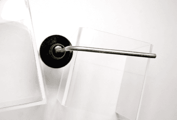
T4FSM061025
May 03, 2010Temperature sensor for food applications
Equipment Class
DSC - Part 15 Security/Remote Control Transmitter
T4F060811RH
Mar 29, 2007Temperature and Relative Humidity Sensor
Equipment Class
DSC - Part 15 Security/Remote Control Transmitter
T4F061213RSO
Mar 29, 2007Temperature and Relative Humidity Sensor
Equipment Class
DSC - Part 15 Security/Remote Control Transmitter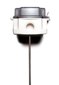
T4F060811TEMP
Mar 29, 2007Temperature Sensor
Equipment Class
DSC - Part 15 Security/Remote Control Transmitter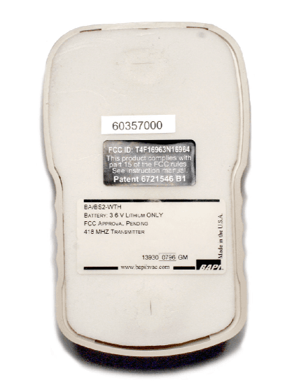
T4F16963N16964
Apr 24, 2006Temperature and Relative Humidity Sensor
Equipment Class
DSC - Part 15 Security/Remote Control Transmitter