T4KAT888UMobile Radio
Qixiang Electron Science& Technology Co., Ltd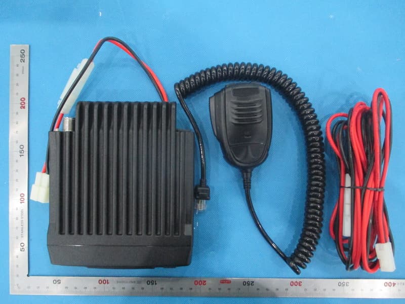
Click to zoom
Application Details
- Equipment Class
- TNB - Licensed Non-Broadcast Station Transmitter
- Date of Grant
- Dec 29, 2014
- Application Purpose
- Original Equipment
- Date of Application
- Dec 29, 2014
- Equipment Note
- Mobile Radio
- Frequency Range
- 406.10000000 - 490.00000000
- Country
- China
Documents & Files
Document Text
Text extracted from the exhibit documents filed with the FCC. Open a document above to read the original.
Users Manual
A T888 FCC ID: T4KAT888U POW SQ L G2 RX G1 TX Mobile Radiao Nice Housing, Stoutness & Stability, Advanced and Concise operation, Perfect & Valuable. Approval. 888 mobile radio especially designs for drivers with high cost performance. NOTE When programming the transceiver, read the factory initial data firstly, then rewrite the frequency and signaling etc., otherwise errors may occur because of different frequency band etc.. Models Apply To This Manual: AT888 Mobile radio 888 Mobile Radio Applicable Software: QPS888 We only do best radio! POW SQ L Thank you for choosing this vehicle transceiver, always provides high quality products, And this transceiver is no exception. As you learn how to use this transceiver, you will find that is pursuing "user operation", this transceiver with the advantage of concise operation and high cost performance. Though concise operation for user, this transceiver is technically and commercially. and some features may be new to you. Consider this manual to be a personal tutorial from the designers, allow the manual to guide you through the learning process now, then act as a reference in the coming years. Do not attempt to configure your transceiver while driving, it is dangerous. This transceiver is designed for a 13.8V DC power supply. Don't use a 24V battery to power on the transceiver. D o n o t p l a c e t h e t r a n s c e i v e r i n excessively dusty, humid or wet areas, nor unstable surfaces. Please keep it away from interferential devices (such as TV, generator etc.). Do not expose the transceiver to long periods of direct sunlight nor place it close to heating appliances. If an abnormal odor or smoke is detected coming from the transceiver, turn OFF the power immediately. Contact an Anytone service station or your dealer. Do not transmit with high output power for extended periods; the transceiver may overheat. Please observe the following precautions to prevent fire, personal injury, or transceiver damage: Precautions Mobile RadioMobile Radio Mobile Radio Supplied Accessories/Optional Accessories ..................... 1 Supplied Accessories ....... ................................................................ 1 Optional Accessories ....... ................................................................ 1 Initial Installation .................................................................. 2 Mobile Installation ....... ..................................................................... 2 DC Power Cable Connection ....... .................................................... 2 Antenna Connection ....... ................................................................. 4 Accessories Connections ........ ......................................................... 4 Getting Acquainted .............................................................. 6 Front panel ....... ................................................................................ 6 Rear panel ....... ................................................................................ 6 Microphone ....... ............................................................................... 7 Basic Operations .................................................................. 8 Switching the Power On ........ ........................................................... 8 Switching the Power Off ........ .......................................................... 8 Adjusting the Volume ....... ............................................................... 8 Channel Selection ....... .................................................................... 8 Receiving ....... .................................................................................. 8 Squelch Level Setup ....... ................................................................. 8 Transmiting Pilot Frequency ....... ..................................................... 9 Transmit 2TONE,5TONE,DTMF ....... ............................................... 9 Restore Facntory Setting ....... .......................................................... 9 P rogramming Software Installing and Starting (in windows XP system) ............................................................................ 10 Install USB Cable Driver Programme ....... ....................................... 10 C ONTENTS Maintenance ..........................................................................11 Default Setting after Resetting(UHF) ....... ........................................11 Trouble Shooting ........ ......................................................................11 Attached Chart ...................................................................... 12 50 groups CTCSS Tone Frequency(Hz) ....... ................................... 12 1024 groups DCS Code. ....... ........................................................... 12 Supplied Accessories 1 1 Supplied Accessories POW SQ L 1 T ransceiverMicrophone User Manual DC Power Cable with Fuse Holder(QPL-01) After carefully unpacking the transceiver, identify the items listed in the table below. We suggest you keep the box and packaging. 2 2 Initial Installation 2 T o install the transceiver, select a safe, convenient location inside your vehicle that minimizes danger to your passengers and yourself while the vehicle is in motion. Consider installing the unit at an appropriate position so that knees or legs will not strike it during sudden braking of your vehicle. Try to pick a well ventilated location that is shielded from direct sunlight. Install the mounting bracket in the vehicle using the supplied self- 11 tapping screws (4pcs) and flat washers (4pcs). P osition the transceiver, then insert and tighten the supplied 21 hexagon SEMS screws. Double check that all screws are tightened to prevent vehicle vibration from loosening the bracket or transceiver . Car body W asher (M5) Tapping screw (M5x20mm) Mounting bracket Mobile installation Determine the appropriate angle of the transceiver…
Text truncated - open the document above for the full version.
Users Manual
AT888 FCC ID: T4KAT888U PO W S Q L G2 RX G1 TX Mobile Radiao Nice Housing, Stoutness & Stability, Advanced and Concise operation, Perfect & Valuable. Approval. 888 mobile radio especially designs for drivers with high cost performance. NOTE When programming the transceiver, read the factory initial data firstly, then rewrite the frequency and signaling etc., otherwise errors may occur because of different frequency band etc.. Models Apply To This Manual: AT888 Mobile radio 888 Mobile Radio Applicable Software: QPS888 We only do best radio! PO W S Q L Thank you for choosing this vehicle transceiver, always provides high quality products, And this transceiver is no exception. As you learn how to use this transceiver, you will find that is pursuing "user operation", this transceiver with the advantage of concise operation and high cost performance. Though concise operation for user, this transceiver is technically and commercially. and some features may be new to you. Consider this manual to be a personal tutorial from the designers, allow the manual to guide you through the learning process now, then act as a reference in the coming years. Do not attempt to configure your transceiver while driving, it is dangerous. This transceiver is designed for a 13.8V DC power supply. Don't use a 24V battery to power on the transceiver. D o n o t p l a c e t h e t r a n s c e i v e r i n excessively dusty, humid or wet areas, nor unstable surfaces. Please keep it away from interferential devices (such as TV, generator etc.). Do not expose the transceiver to long periods of direct sunlight nor place it close to heating appliances. If an abnormal odor or smoke is detected coming from the transceiver, turn OFF the power immediately. Contact an Anytone service station or your dealer. Do not transmit with high output power for extended periods; the transceiver may overheat. Please observe the following precautions to prevent fire, personal injury, or transceiver damage: Precautions Mobile RadioMobile Radio Mobile Radio Supplied Accessories/Optional Accessories .....................1 Supplied Accessories .......................................................................1 Optional Accessories .......................................................................1 Initial Installation ..................................................................2 Mobile Installation ............................................................................2 DC Power Cable Connection ...........................................................2 Antenna Connection ........................................................................4 Accessories Connections .................................................................4 Getting Acquainted ..............................................................6 Front panel .......................................................................................6 Rear panel .......................................................................................6 Microphone ......................................................................................7 Basic Operations ..................................................................8 Switching the Power On ...................................................................8 Switching the Power Off ..................................................................8 Adjusting the Volume ......................................................................8 Channel Selection ...........................................................................8 Receiving .........................................................................................8 Squelch Level Setup ........................................................................8 Transmiting Pilot Frequency ............................................................9 Transmit 2TONE,5TONE,DTMF ......................................................9 Restore Facntory Setting .................................................................9 Programming Software Installing and Starting (in windows XP system) ............................................................................10 Install USB Cable Driver Programme ..............................................10 CONTENTS Maintenance ..........................................................................11 Default Setting after Resetting(UHF) ...............................................11 Trouble Shooting ..............................................................................11 Attached Chart ...................................................................... 12 50 groups CTCSS Tone Frequency(Hz) .......................................... 12 1024 groups DCS Code. .................................................................. 12 Supplied Accessories 1 1 Supplied Accessories PO W S Q L 1 Transceiver Microphone User Manual DC Power Cable with Fuse Holder(QPL-01) After carefully unpacking the transceiver, identify the items listed in the table below. We suggest you keep the box and packaging. 2 2 Initial Installation 2 To install the transceiver, select a safe, convenient location inside your vehicle that minimizes danger to your passengers and yourself while the vehicle is in motion. Consider installing the unit at an appropriate position so that knees or legs will not strike it during sudden braking of your vehicle. Try to pick a well ventilated location that is shielded from direct sunlight. Install the mounting bracket in the vehicle using the supplied self- 11 tapping screws (4pcs) and flat washers (4pcs). Position the transceiver, then insert and tighten the supplied 21 hexagon SEMS screws. Double check that all screws are tightened to prevent vehicle vibration from loosening the bracket or transceiver. Car body Washer (M5) Tapping screw (M5x20mm) Mounting bracket Mobile installation Determine the appropriate angle of the transceiver, using the 3 screw hole positions on the side…
Text truncated - open the document above for the full version.
Users Manual
AT888 FCC ID: T4KAT888U PO W S Q L G2 RX G1 TX Mobile Radiao Nice Housing, Stoutness & Stability, Advanced and Concise operation, Perfect & Valuable. Approval. 888 mobile radio especially designs for drivers with high cost performance. NOTE When programming the transceiver, read the factory initial data firstly, then rewrite the frequency and signaling etc., otherwise errors may occur because of different frequency band etc.. Models Apply To This Manual: AT888 Mobile radio 888 Mobile Radio Applicable Software: QPS888 We only do best radio! PO W S Q L Thank you for choosing this vehicle transceiver, always provides high quality products, And this transceiver is no exception. As you learn how to use this transceiver, you will find that is pursuing "user operation", this transceiver with the advantage of concise operation and high cost performance. Though concise operation for user, this transceiver is technically and commercially. and some features may be new to you. Consider this manual to be a personal tutorial from the designers, allow the manual to guide you through the learning process now, then act as a reference in the coming years. Do not attempt to configure your transceiver while driving, it is dangerous. This transceiver is designed for a 13.8V DC power supply. Don't use a 24V battery to power on the transceiver. D o n o t p l a c e t h e t r a n s c e i v e r i n excessively dusty, humid or wet areas, nor unstable surfaces. Please keep it away from interferential devices (such as TV, generator etc.). Do not expose the transceiver to long periods of direct sunlight nor place it close to heating appliances. If an abnormal odor or smoke is detected coming from the transceiver, turn OFF the power immediately. Contact an Anytone service station or your dealer. Do not transmit with high output power for extended periods; the transceiver may overheat. Please observe the following precautions to prevent fire, personal injury, or transceiver damage: Precautions Mobile RadioMobile Radio Mobile Radio Supplied Accessories/Optional Accessories .....................1 Supplied Accessories .......................................................................1 Optional Accessories .......................................................................1 Initial Installation ..................................................................2 Mobile Installation ............................................................................2 DC Power Cable Connection ...........................................................2 Antenna Connection ........................................................................4 Accessories Connections .................................................................4 Getting Acquainted ..............................................................6 Front panel .......................................................................................6 Rear panel .......................................................................................6 Microphone ......................................................................................7 Basic Operations ..................................................................8 Switching the Power On ...................................................................8 Switching the Power Off ..................................................................8 Adjusting the Volume ......................................................................8 Channel Selection ...........................................................................8 Receiving .........................................................................................8 Squelch Level Setup ........................................................................8 Transmiting Pilot Frequency ............................................................9 Transmit 2TONE,5TONE,DTMF ......................................................9 Restore Facntory Setting .................................................................9 Programming Software Installing and Starting (in windows XP system) ............................................................................10 Install USB Cable Driver Programme ..............................................10 CONTENTS Maintenance ..........................................................................11 Default Setting after Resetting(UHF) ...............................................11 Trouble Shooting ..............................................................................11 Attached Chart ...................................................................... 12 50 groups CTCSS Tone Frequency(Hz) .......................................... 12 1024 groups DCS Code. .................................................................. 12 Supplied Accessories 1 1 Supplied Accessories PO W S Q L 1 TransceiverMicrophone User Manual DC Power Cable with Fuse Holder(QPL-01) After carefully unpacking the transceiver, identify the items listed in the table below. We suggest you keep the box and packaging. 2 2 Initial Installation 2 To install the transceiver, select a safe, convenient location inside your vehicle that minimizes danger to your passengers and yourself while the vehicle is in motion. Consider installing the unit at an appropriate position so that knees or legs will not strike it during sudden braking of your vehicle. Try to pick a well ventilated location that is shielded from direct sunlight. Install the mounting bracket in the vehicle using the supplied self- 11 tapping screws (4pcs) and flat washers (4pcs). Position the transceiver, then insert and tighten the supplied 21 hexagon SEMS screws. Double check that all screws are tightened to prevent vehicle vibration from loosening the bracket or transceiver. Car body Washer (M5) Tapping screw (M5x20mm) Mounting bracket Mobile installation Determine the appropriate angle of the transceiver, using the 3 screw hole positions on the side …
Text truncated - open the document above for the full version.
Users Manual
Mobile RadioMobile Radio TraiTrai Qixiang Electron Scien c R&D Re Safety UsageSafety Usage ningning c e&Technology Co., Ltd. paired Department 2015.10.20 AT 888U M AT - 888U M o bil R dibil e R a di o AT 888U M bil R di AT - 888U M o bil e R a di • Frequency Range:400 ‐ 490MHz • Output Power:45 Watts iIfi o I n f o M bil R di W kiM o bil e R a di o W or kin Cdii n g C on di t i on M bil R di S fM o bil e R a di o S a f et y • This radio generates RF electromagnetic • This radio is designed for and classified a be used only during the course of empl o hazards,and the ways to minimize with h b th "G l P l ti " i b y th e "G enera l P opu l a ti on " i n an unco n • For Compliance with FCC and Industry C transmitter antenna installation shall co m • 1.The transmitter antenna gain shall not • 2.The antenna is required to be loacted o of 51 6 centimeters or more between th of 51 . 6 centimeters or more between th any persons during opeation. For samll v located on the roof top at any place on t achieve 51.6 centimeters separation dist achieve 51.6 centimeters separation dist met,the installation of the antenna mus t away form the nearest edge of the vehi c bystanders Ii y I nstruct i on energy during transmission. a s"Occupational Use Only",meaning it must o yament by individuals aware of the h azards.This radio is NOT intended for use tlld it nt ro ll e d env i romen t . anada RF Exposure Requirements,the mp l y with the followin g two conditions: py g exceed 0 dBi o utside of a vehicle and kept at a distance e transmitting antenna of this device and e transmitting antenna of this device and v ehicle as worst case, the antenna shall be t he center line along the vehicle in order to tance. In order to ensure this distance is tance. In order to ensure this distance is t be mounted at least 51.6 centimeters c le in order to protect against exposure to Mobile Radio SafetyMobile Radio Safety Caution: • To ensure that your exposure to RF elec t allowable limits for occupational use alw allowable limits for occupational use , alw • DO NOT operate the radio without a pr o damage the radio and may also cause y o proper atnenna is the antenna supplied proper atnenna is the antenna supplied antenna specifically authorized by the m • DO NOT transmit for more than 50% du r l l)T itti i cyc l e or l ess ) . T ransm itti ng excess i ve am o compliance requirements to be exceede to learn how to transmit and stop trans m y Instructiony Instruction t romagnetic engergy is within the FCC ways adhere to the following guidelines: ways adhere to the following guidelines: o per antenna attached,as this may o u to exceed FCC RF exposure limites. A with this radio by the manufacturer or an with this radio by the manufacturer or an m anufacturer for use with this radio. r ing the time of employment(50% duty t f ti RF o un t o f ti me can cause RF exposure d.Please carefully read intruction manual m itting before starting to use it M bil R di S fM o bil e R a di o S a f et y Electromagnetic Interference/Compatib i • Durin g transmissions ,y our radio g ener a g ,y g interference with other devices or syst the radio in areas where signs are pos t transmitter in areas that are sensitive transmitter in areas that are sensitive hospitals,aircraft and blasting sites Occupational/Controlled USe • This Products is used in situations that consequence of their empolyment pro potential RF hazards and can exercise c potential RF hazards and can exercise c • This transceiver is NOT ATEX approved hazardous ex p losive atmos p heres p p Ii y I nstruct i on i lity a tes RF ener gy that can p ossilbl y cause gy py ems,To avoid such interference,turn off t ed to do so .DO NOT operate the to electromagnetci radiation such as to electromagnetci radiation such as users are exposed to RF as vided those users are fully aware of the control over their exposure control over their exposure and NOT intended for the use in l Qixiang E l ectron Science& T hl d T ec h no l ogy Co., Lt d .
Cover Letter(s)
Dec.25, 2014 Federal Communication Commission Authorization and Evaluation Division FCC ID: T4KAT888U Re: Confidentiality Request Pursuant to Sections 0.457 and 0.459 of the Commission’s Rules, the applicant hereby requests confidential treatment of information applied this application as outlined below: 1: Block Diagram 2: Circuit Diagram 3: Operational Description 4: Parts List 5.Tune Up Procedure The above materials contain trade secrets and proprietary information not customarily released to the public. The public disclosure of these matters might be harmful to the applicant and provide unjustified benefits to its competitors. The Applicant understands that pursuant to Rules 0.457, disclosure of this Application and all accompanying documentation will not be made before the date of the Grant for this application. Sincerely, Qixiang Electron Science& Technology Co., Ltd Contact person: Ken Xu Title: General manager
Cover Letter(s)
Dec.25, 2014 Federal Communication Commission Authorization and Evaluation Division Subject: FCC ID: T4KAT888U Justification Letter for Expanded Frequency Range 400-490MHz Gentlemen; This transmitter was design to operate in the frequency range of 400-490MHz. To aid equipment authorization in other countries that accept the United States FCC Grant for Certification, Qixiang Electron Science& Technology Co., Ltd is requesting that the FCC list the above frequency/frequencies under FCC Rule Parts 90 on the Grant. For the FCC’s Rule Parts 90 applications, this radio is used in systems by Federal and Public Safety agencies including Police, Fire, and Emergency Medical Services, etc. as indicated in the table below. Equipment programming is the responsibility of Authorized Service Personnel. Also, the radio complies with 47 CFR Part 90.203(e), in that the operator cannot directly program the transmit frequencies using the normally accessible external controls. Per the FCC’s KDB634817 guidance, as an alternative to listing the exact frequencies, we acknowledge that it’s a violation of the FCC Rules if this device operates on unauthorized frequencies. Sincerely, Qixiang Electron Science& Technology Co., Ltd Ken Xu /General Manager
Cover Letter(s)
Qixiang Electron Science& Technology Co., Ltd Qixiang Building, Tangxi Industrial Zone, Luojiang Quanzhou, Fujian, China Tel: 86-592-22652998 Fax: 86-595-22656927 Dec.25.2014 To: Federal Communication Commission Authorization and Evaluation Division Subject: Attestation statement regarding the Mobile Radio frequency TYPE OF QEUIPMENT: Licensed Non-Broadcast Station Transmitter FCC ID: T4KAT888U Dear Sir or Madam We, Qixiang Electron Science& Technology Co., Ltd acknowledge this equipment meets the requirements of FCC Rules, Parts 90.203 (e) and (g)(1) as applicable. This device will not be marketed to US users with frequency bands which are not allowed by the rule part 90 and the operation on unauthorized frequencies inside the USA is a violation of the FCC rules. The device meets the requirements of part 90.203 (g). When you program the software of QSP888 has to be used with professional cable in Windows XP system. Only the frequency point within permissible could be programmed. Please contact the undersigned if you have any questions or need any further information. Regards Qixiang Electron Science& Technology Co., Ltd Signature: Name, Job Title and Dept.: Ken Xu / General Manager
External Photos
External Photos TOTAL VIEW OF EUT TOP VIEW OF EUT BOTTOM VIEW OF EUT FRONT VIEW OF EUT BACK VIEW OF EUT LEFT VIEW OF EUT RIGHT VIEW OF EUT
ID Label/Location Info
FCC ID Label Location FCC RF Warning Label Mobile RADIO Model: AT888 FCC ID: T4KAT888U AT999, AT555, AT889, AT899, AT888U, AT899U, AT999U, AT555U, AT889U, AT899U, AT888U, AT 8 9 9
Internal Photos
Internal Photos OPEN VIEW-1 OF EUT OPEN VIEW-2 OF EUT OPEN VIEW-3 OF EUT OPEN VIEW-4 OF EUT OPEN VIEW-5 OF EUT OPEN VIEW-6 OF EUT INTERNAL VIEW-1 OF EUT INTERNAL VIEW-2 OF EUT INTERNAL VIEW-3 OF EUT INTERNAL VIEW-4 OF EUT INTERNAL VIEW-5 OF EUT INTERNAL VIEW-6 OF EUT
RF Exposure Info
Page 1 of 9 OET Bulletin 65 (MPE) Test Report Report No.: AGC00589141206FH07 FCC ID : T4KAT888U PRODUCT DESIGNATION : MOBILE RADIO BRAND NAME : N/A TEST MODEL : AT888, AT999, AT555, AT889, AT899, AT888U, AT899U, AT999U, AT555U, AT889U, AT899U, AT888U, AT899 CLIENT : Qixiang Electron Science & Technology Co., Ltd. DATE OF ISSUE : Dec.23, 2014 STANDARD(S) : OET Bulletin 65 REPORT VERSION : V1.0 Attestation of Global Compliance (Shenzhen) Co., Ltd CAUTION: This report shall not be reproduced except in full without the written permission of the test laboratory and shall not be quoted out of context. Report No.: AGC00589141206FH07 Page 2 of 9 Report Revise Record Report Version Revise Time Issued Date Valid Version Notes V1.0 / Dec.23, 2014 Valid Original Report Report No.: AGC00589141206FH07 Page 3 of 9 TABALE OF CONTENTS TABALE OF CONTENTS .................................................................................................................................. 2 1. TEST RESULT CERTIFICATION ................................................................................................................... 4 2. TECHNICAL INFORMATION ......................................................................................................................... 5 3. RF EXPOSURE MEASUREMENT ................................................................................................................. 5 3.1 INTRODUCTION ...................................................................................................................................... 6 3.2 FCC LIMITS FOR MAXIMUM PERMISSIBLE EXPOSURE (MPE) .......................................................... 7 4. CLASSIFICATION OF THE ASSESSMENT METHODS ............................................................................... 8 5. EUT OPERATION CONDITION ..................................................................................................................... 8 6. TEST RESULTS ............................................................................................................................................. 9 Report No.: AGC00589141206FH07 Page 4 of 9 1. TEST RESULT CERTIFICATION Applicant Name: Qixiang Electron Science & Technology Co., Ltd. Address: Qixiang Building, Tangxi Industrial Zone, Luojiang District, Quanzhou, Fujian, China Manufacturer Name: Qixiang Electron Science & Technology Co., Ltd. Address: Qixiang Building, Tangxi Industrial Zone, Luojiang District, Quanzhou, Fujian, China Product Designation: MOBILE RADIO Brand Name: N/A Test Model AT888 Series Model AT999, AT555, AT889, AT899, AT888U, AT899U, AT999U, AT555U, AT889U, AT899U, AT888U, AT899 Difference description All the same except for the model name. Date of Test: Dec.17, 2014 to Dec.22, 2014 We (AGC), Attestation of Global Compliance (Shenzhen) Co., Ltd. for compliance with the requirements set forth in the FCC Standard OET Bulletin 65 (Edition 97-01) Supplement C (Edition 01-01). The results of testing in this report apply to the product/system which was tested only. Tested by Freddie Duan Dec.23, 2014 Checked By Kidd Yang Dec.23, 2014 Authorized By Solger Zhang Dec.23, 2014 Report No.: AGC00589141206FH07 Page 5 of 9 2. TECHNICAL INFORMATION Note: the following data is based on the information by the applicant. EUT DESCRIPTION The EUT is a MOBILE RADIO designed for voice communication. It is designed by way of utilizing the FM modulation achieves the system operating. A major technical description of EUT is described as following: Operation Frequency 400MHz to 490MHz Modulation FM Antenna Designation Detachable Antenna Output power Modification 45W antenna connector SMA Antenna type External antenna Antenna gain 0dBi Antenna connection cable length 2m Power Supply DC13.8V Report No.: AGC00589141206FH07 Page 6 of 9 3. RF EXPOSURE MEASUREMENT 3.1 INTRODUCTION Human exposure to RF emissions from mobile devices (47 CFR §2.1091) may be evaluated based on the MPE limits adopted by the FCC for electric and magnetic field …
Text truncated - open the document above for the full version.
Contact Information
Applicant
Ken Xu
Test Firm
Attestation of Global Compliance Shenzhen Co. Ltd.Forrest Lei
Technical Specifications
| # | Rule Parts | Frequency Range | Power Output | Emission | Tolerance |
|---|---|---|---|---|---|
| 2 | 9 | 406.1 MHz - 490 MHz | 45 W | 10K2F3E | 0.7 ppm |
Other Applications from Qixiang Electron Science& Technology Co., Ltd

T4K-AT5100
Jul 28, 202610 METER AMATEUR RADIO
Equipment Class
DTS - Digital Transmission System
T4K-UA1
Apr 07, 2026HANDHELD TRANSCEIVER
Equipment Class
CSR - Scanning Receiver
T4K-UVA1
Mar 30, 2026DUAL BAND HANDHELD TRANSCEIVER
Equipment Class
CSR - Scanning Receiver
T4K-AT-505
Jan 19, 2026CB Radio
Equipment Class
JAV - Other Non-Digital SDoC Devices
T4K-D890UV
Jan 07, 2026Multi-Protocol Digital+Analog Handheld Radio
Equipment Class
DSS - Part 15 Spread Spectrum Transmitter