T82TWF600TPokayoke Transmitter
Herutu Electronics Corporation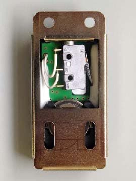
Click to zoom
Application Details
- Equipment Class
- DXT - Part 15 Low Power Transceiver, Rx Verified
- Date of Grant
- May 28, 2007
- Application Purpose
- Original Equipment
- Date of Application
- May 28, 2007
- Equipment Note
- Pokayoke Transmitter
- Frequency Range
- 426.10000000 - 426.10000000
- Country
- Japan
Documents & Files
Document Text
Text extracted from the exhibit documents filed with the FCC. Open a document above to read the original.
Users Manual
POKAYOKE TRANSMITTER TWF600T Users Manual V1.02 i Safety concerns (Be sure to read) To prevent human injury of user or damage in property from occurring, be sure to observe the precautions shown below. The degree in safety hazard and damage generated by the wrong usage while ignoring the descriptions is classified by the following displays. Using in an improper way while ignoring this pictorial symbol mightcause a death or serious human injury. Using in an improper way while ignoring this pictorial symbol might cause a human injury or property damage. The type of descriptions you should observe is classified by the following pictorial symbols. This pictorial symbol indicates a “Reminder” to attract an attention. This pictorial symbol indicates a “Prohibition” to prohibit a certain action. For the usage to be commonly applied in all the models: Avoid using in a place with a plenty of humidity or dust. Otherwise, absorbing a dust or water contents may cause machine trouble, fire or electrical shock. For handling this machine: This is the electronic devise or wireless radios composed of the precision parts. Do not overhaul/remodel. It may cause accident or machine trouble. For handling this machine: Do not use this product for the application needing the high reliability related to human lives. Do not use this product in a place where it is uncertain about whether or not radio waves reach. Warning ! Caution ! ! ! Warning ! ii For handling the power source: Be sure to observe the following precautions to prevent the AC adapter and Power cord from being heated, damaged, or ignited. Do not approximate the AC adapter and Power cord to a fire, or do not put them into a fire. The AC adapter and Power cord can be broken or ignited, resulting in an accident. You can use the AC adapter and main body only with the specified power voltage to protect them from the damage and fire accident. Do not use the AC adapter and main body in a wettable atmosphere. It may cause accidents or troubles such as heating, igniting or electrical shock. Do not touch the AC adapter, main body, Power cord and Plug outlet with wet hands. It may cause an accident such as electrical shock, etc. Do not damage the Power cord. A short-circuit or heating may cause a fire or electrical shock. Do not use the Power plug with dust being adhered. A short-circuit or heating may cause a fire or electrical shock. Do not give a strong impact onto the AC adapter. It may cause an accident or machine failure. If you find out deformed AC adapter, do not use it. It may cause an accident or machine failure. Do not charge this equipment in a place where flammable gas can be generated. It may cause a fire accident. Never overhaul the AC adapter. It may cause an accident or machine failure. When trouble happens during use: Since it may cause a fire or electrical shock, disconnect a power plug, and immediately ask outlet store or our company to repair. When smoke or abnormal odors are generated, stop using, immediately disconnect a power plug, and ask outlet store or our company to repair. Once the Power cord is damaged, do not use it. Using it as is may cause a fire or electrical shock. Warning ! iii CAUTION INFORMATION ABOUT FCC STANDARD FCC WARNING! CHANGE OR MODIFICATIONS NOT EXPRESSLY APPROVED BY THE MANUFACTURE FOR COMPLIANCE COULD VOID THE USER’S AUTHORITY TOOPERATE THE EQUIPMENT THE FOLLOWNG APPLIES ONLY IN THE U.S.A This device complies with Part 15 of the FCC Rules. Operation is subject to the following two conditions: (1) This device may not cause harmful interface, and (2) This device must accept any interface received, including interface that may cause undesired operation: TO REDUCE THE ELECTRIC SHOCK, DO NOT REMOVE SCREWS. NO USER-SERVICEABLE PARTS INSIDE. REFER SERVICING TO QUALIFIED SERVICE PERSONNEL. Contents 1.General descriptions.............................................................................................................. 1 2.Specifications.......................................................................................................................... 2 3.Dimensional drawing............................................................................................................. 3 4.To install on the Torque wrench.......................................................................................... 6 4-1.Preparation for installation................................................................................................... 6 4-2.Installation............................................................................................................................. 8 5.How to use Radio Transmitter........................................................................................... 10 5-1.Checking the battery........................................................................................................... 10 5-2.Operating timing................................................................................................................. 10 5-3. Replacing the battery......................................................................................................... 11 6.Registering ID........................................................................................................................ 12 7. Precautions during use............................................................................................................ 13 8. Troubleshooting....................................................................................................................... 14 9.Guarantee................................................................................................................................ 15 1 1.General descriptions This operation manual contains the instructions necessary for using the “POKAYOKE Transmitter TWF-600T” (hereinafter specified as “TWF-600T”). Thoroughly read through this manual before use to correctly operate. Once the TWF-600T is…
Text truncated - open the document above for the full version.
External Photos
External Photo HERUTU ELECTRONICS CORPORATION POKAYOKE TRANSMITTER Model: TWF-600T FCC ID: T82TWF600T Front Rear External Photo HERUTU ELECTRONICS CORPORATION POKAYOKE TRANSMITTER Model: TWF-600T FCC ID: T82TWF600T Top Bottom External Photo HERUTU ELECTRONICS CORPORATION POKAYOKE TRANSMITTER Model: TWF-600T FCC ID: T82TWF600T Right Left
ID Label/Location Info
FCC ID T82TWF600T TWF-600T NamePlate Label DESIGN CHECK APPROVAL PAGE DATE DRAWING No TITLE HERUTU ELECTRONICS COR PORATION 2007/4/25 1 1 401062-01-1 MODEL TWF-600T SCALE=2:1DIMENSIONS in MM Materials : Polyester film with glue on the bac k side
Internal Photos
Internal Photo HERUTU ELECTRONICS CORPORATION POKAYOKE TRANSMITTER Model: TWF-600T FCC ID: T82TWF600T Top Bottom Internal Photo HERUTU ELECTRONICS CORPORATION POKAYOKE TRANSMITTER Model: TWF-600T FCC ID: T82TWF600T Internal
Test Report
FCC ID : T82TWF600T Test report No. : 27HE0238-YK Page : 2 of 20 Issued date : May 16, 2007 UL Japan, Inc. YAMAKITA EMC LAB. 907 Kawanishi, Yamakita-machi, Ashigarakami-gun, Kanagawa-ken, 258-0124 JAPAN Telephone: +81 465 77 1011 Facsimile: +81 465 77 2112 MF060b (26.04.07) Table of Contents Page 1 Applicant Information 3 2 Product Description 4 3 Test Specification, Procedures and Results 5 4 System Test Configuration 7 5 Automatically deactivate 8 6 Radiated Emissions 9 7 20dB Bandwidth 10 Contents of Appendixes 11 APPENDIX 1: Photographs of test setup 12 APPENDIX 2: Test Data 14 APPENDIX 3: Test instruments 20 FCC ID : T82TWF600T Test report No. : 27HE0238-YK Page : 3 of 20 Issued date : May 16, 2007 UL Japan, Inc. YAMAKITA EMC LAB. 907 Kawanishi, Yamakita-machi, Ashigarakami-gun, Kanagawa-ken, 258-0124 JAPAN Telephone: +81 465 77 1011 Facsimile: +81 465 77 2112 MF060b (26.04.07) 1 Applicant Information Company Name : HERUTU ELECTRONICS CORPORATION Address : 62-1 Toyooka-cho, Kita-ku, Hamamatsu-shi, Shizuoka-ken, 433-8103 JAPAN Telephone Number : +81-53-438-3555 Facsimile Number : +81-53-438-3411 Contact Person : Masayuki Oishi FCC ID : T82TWF600T Test report No. : 27HE0238-YK Page : 4 of 20 Issued date : May 16, 2007 UL Japan, Inc. YAMAKITA EMC LAB. 907 Kawanishi, Yamakita-machi, Ashigarakami-gun, Kanagawa-ken, 258-0124 JAPAN Telephone: +81 465 77 1011 Facsimile: +81 465 77 2112 MF060b (26.04.07) 2 Product Description Type of Equipment : POKAYOKE TRANSMITTER Model No. : TWF-600T Serial No. : Automatically deactivate: 001, Other test: 002 Rating : DC 3.0V Country of Manufacture : Japan Receipt Date of Sample : May 7, 2007 Condition of EUT : Production model Modification of EUT : No modification by the test lab. Model: TWF-600T (referred to as the EUT in this report) is a POKAYOKE TRANSMITTER which is composed of a fitting frame equipped with touch sensor and a radio transmitter. Equipment type : Transmitter Operation temperature range : 0 ~ 50 deg. C. Other clock frequency : 5.0MHz (CPU) Emission designation : F1D Frequency of operation : 426.100000MHz (multiple: ×6) Crystal oscillation frequency : 71.016666MHz Modulation : FSK Antenna type : Built to the foundation FCC Part15.31 (e) The EUT provides stable voltage, DC2.2V constantly to RF module regardless of input voltage, and the test was performed with the new battery. Therefore, the EUT complies with the power supply regulation. FCC Part15.203 Antenna requirement It is impossible for users to replace the antenna because the antenna is mounted inside the EUT. Therefore, the EUT complies with the antenna requirement. FCC ID : T82TWF600T Test report No. : 27HE0238-YK Page : 5 of 20 Issued date : May 16, 2007 UL Japan, Inc. YAMAKITA EMC LAB. 907 Kawanishi, Yamakita-machi, Ashigarakami-gun, Kanagawa-ken, 258-0124 JAPAN Telephone: +81 465 77 1011 Facsimile: +81 465 77 2112 MF060b (26.04.07) 3 Test Specification, Procedures and Results 3.1 Test specification Test specification : FCC Part15 Subpart C: 2006 Title : FCC 47CFR Part15 Radio Frequency Device Subpart C Intentional Radiators Section 15.209 Radiated emission limits, general requirements Section 15.231 Periodic operation in the band 40.66 - 40.70 MHz and above 70 MHz 3.2 Procedures & Results Item Test Procedure Specification Remarks DeviationWorst Margin Results Conducted Emission ANSI C63.4: 2003 7. AC powerline conducted emission measurements Section 15.207(a) AC Mains N/A *1 - N/A Automatically Deactivate ANSI C63.4: 2003 Section 15.231(a)(1) Radiated N/A - Complied Electric Field Strength of Fundamental Emission ANSI C63.4: 2003 13. Measurement of intentional radiators Section 15.231(b) Radiated N/A 9.5dB (PK, Horizontal) Complied Electric Field Strength of Spurious Emission ANSI C63.4: 2003 13. Measurement of intentional radiators Section 15.209 *2 Radiated N/A 7.8dB (1917.48MHz, AV, Vertical) Complied -20dB Bandwidth ANSI C63.4: 2003 Annex H.6 Occupied bandwidth measurements Section 15.231(c) Radiated N/A - Complied *1) The test is not applicable since the EUT has no AC mains. *2) For Spurious emission, Section 15.209 has been applied since the limit is stricter than in Section 15.231(b). Note: UL Japan’s EMI Work Procedures No.QPM05. * Other than mentioned in 3.3, no addition, exclusion nor deviation has been made from the standard. 3.3 Addition to standard Item Test Procedure Specification Remarks Worst Margin Results Occupied Bandwidth (99%) ANSI C63.4:2003 13. Measurement of intentional radiators RSS-Gen 4.4.1 RSS-Gen 4.4.1 Conducted *See data. Complied FCC ID : T82TWF600T Test report No. : 27HE0238-YK Page : 6 of 20 Issued date : May 16, 2007 UL Japan, Inc. YAMAKITA EMC LAB. 907 Kawanishi, Yamakita-machi, Ashigarakami-gun, Kanagawa-ken, 258-0124 JAPAN Telephone: +81 465 77 1011 Facsimile: +81 465 77 2112 MF060b (26.04.07) 3.4 Uncertainty The measurement uncertainty (with a 95% confidence level) is as follows: No.1 open site No.2 open site No.1 anechoic chamber Conducted emission 150kHz-30MHz 2.8 dB 2.8 dB 2.8 dB Radiated emission (3m) 30-300MHz 4.5 dB 4.4 dB 4.5 dB 300-1000MHz 4.3 dB 4.3 dB 4.3 dB 1GHz< 5.7 dB 5.7 dB 5.7 dB Radiated emission (10m) 30-300MHz 4.5 dB 4.4 dB - 300-1000MHz 4.1 dB 4.1 dB - Radiated Emission Test The data listed in this test report has enough margin, more than site margin. 3.5 Test Location UL Japan, Inc. Yamakita EMC Lab. 907, Kawanishi, Yamakita-machi, Ashigarakami-gun, Kanagawa-ken 258-0124 JAPAN Telephone number : +81 465 77 1011 Facsimile number : +81 465 77 2112 NVLAP Lab. code : 200441-0 No. 1 test site has been fully described in a report submitted to FCC office, and accepted on August 26, 2005 (Registration No.: 95486). IC Registration No. : 2973B-1 No. 2 test site has been fully described in a report submitted to FCC office, and accepted on April 4, 2005 (Registration No.: 466226). IC Registration No. : 2973B-3 No. 1 anechoic chamber has been fully described in a report submitted to FCC office, and accepted on November 2, 2005 (Regi…
Text truncated - open the document above for the full version.
Test Setup Photos
FCC ID : T82TWF600T Test report No. : 27HE0238-YK Page : 12 of 20 Issued date : May 16, 2007 UL Japan, Inc. YAMAKITA EMC LAB. 907 Kawanishi, Yamakita-machi, Ashigarakami-gun, Kanagawa-ken, 258-0124 JAPAN Telephone: +81 465 77 1011 Facsimile: +81 465 77 2112 MF060b (26.04.07) Radiated emission FCC ID : T82TWF600T Test report No. : 27HE0238-YK Page : 13 of 20 Issued date : May 16, 2007 UL Japan, Inc. YAMAKITA EMC LAB. 907 Kawanishi, Yamakita-machi, Ashigarakami-gun, Kanagawa-ken, 258-0124 JAPAN Telephone: +81 465 77 1011 Facsimile: +81 465 77 2112 MF060b (26.04.07) Pre-check of worst position EUT: Y-axis EUT: X-axis EUT: Z-axis
Contact Information
Applicant
Yoshiyasu Ueda
Technical Contact
UL Japan, IncTatsuya Arai
[email protected]81-465-77-1011
907 Kawanishi, Yamakita-machi · Ashigarakami-gun, Kanagawa-ken · Japan
Non-Technical Contact
UL JapanYoshinobu Asai
[email protected]81-596-24-8116
Test Firm
UL Japan, IncMitsuru Fujimura
Technical Specifications
| # | Rule Parts | Frequency Range | Power Output |
|---|---|---|---|
| 1 | 15C | 426.1 MHz - 426.1 MHz | - |
Other Applications from Herutu Electronics Corporation

T82-HRF2403
Jan 21, 20212.4 GHz Wireless Module
Equipment Class
DTS - Digital Transmission System
T82HRF-2401
Aug 25, 2015Equipment built-in 2.4GHz band transceiver module
Equipment Class
DTS - Digital Transmission System
T82-TW800T
Nov 14, 2012POKAYOKE TRANSMITTER
Equipment Class
DXX - Part 15 Low Power Communication Device Transmitter
T82-TW800R
Nov 14, 2012POKAYOKE RECEIVER
Equipment Class
DXX - Part 15 Low Power Communication Device Transmitter