T8C003Telecody - Keypad Transmitter
SOMMER Antriebs- und Funktechnik GmbH
Click to zoom
Application Details
- Equipment Class
- DSC - Part 15 Security/Remote Control Transmitter
- Date of Grant
- Oct 30, 2007
- Application Purpose
- Original Equipment
- Date of Application
- Oct 30, 2007
- Equipment Note
- Telecody - Keypad Transmitter
- Frequency Range
- 315.00000000 - 315.00000000
- Country
- Germany
Documents & Files
Document Text
Text extracted from the exhibit documents filed with the FCC. Open a document above to read the original.
Users Manual
1 of 14 Telecody Keypad Transmitter (US) WARNING There is a possible risk of injury or death if safety instructions will not be observed. Please read and follow all instructions in this manual as well as the information for each receiver you are planning to operate with this device. Please share this important information with other users. No modifications to this device are permissible. Modifications performed to this device other than described in this manual or granted by the manufacturer, will result in the loss of the operating license. This device complies with FCC rules part 15. The operation of this device is subject to the following conditions: (1) This device may not cause harmful interference, and (2) This device must accept any interference received, including interference that may cause undesired operation. Use only original equipment manufacturer (OEM) parts and accessories as well as fixing supplies. Do not expose this device to a power pressure washer or to a water hose as water may penetrate into the interior and damage or destroy this device. Serial number label On the outside of the Telecody Keypad is a label which indicates the serial number. The factory preprogrammed access codes (see chapter programming access codes) can only be deleted by using this serial number. Otherwise the transmitter needs to be returned to the factory for the deletion of these access codes. Attach this label in a secure location for example: your address book or the controller housing of your operator Operation The transmitter sends a signal to a receiver i.e. the garage door opener which will result in an opening and closing of the garage door. To prevent unwanted operation of the keypad it is advisable to program access codes to the transmitter. The Telecody Keypad was developed for the exterior operation. Simply use the included holder and attach to either a wall or to the garage door frame if available. 2 of 14 Technical data: Frequency 315 MHz Operational temperature -5° to +130°F (-20 C to +55 C) Range Approx. 75ft (23 m) (depending on surroundings) IP Rating IP 64 Battery (included) Lithium CR 123 A, 3Volt Dimensions Height: 5-13/16 (147 mm) (incl. holder) Width: 1-7/8 (48 mm) Depth: 1-3/16 (30 mm) Weight (Incl. battery and holder) Approx. 6.4 oz (180 g) Radio codes 12 different codes (10 codes with programmable access codes and 2 without) 3 of 14 Scope of delivery Please check package contents. In case something is missing, please contact your dealer who will be happy to assist. Please do dispose packaging according to your local waste regulations. 1) Transmitter assembled 2) Battery (already inserted) 3) Holder (attach to either a wall or to the garage door frame if available) 4) 2 screws to mount the holder 5) 2 anchors 3/16 (Ø 6 mm) 6) 1 screw to attach the transmitter to the holder 7) 1 installation and operating manual Required tools 1) Hammer Drill 2) Drill bit for masonry 3) Phillips screwdriver (medium) 4) Hammer 5) Measuring Tape 6) Level 7) Pencil 4 of 14 Installation and installation requirements WARNING There is a possible risk of injury or death if safety instructions will not be observed. The transmitter shall only be installed if the following installation requirements are given. For the installation, choose an easy accessible location within the transmitter range. The distance from the ground needs to be at least 5 (1.50 meter) to prevent that children could play with the transmitter. Mount the holder on a flat surface. To control a door opener or gate operator with the transmitter, please select the installation location as follows: -away from the door and the operator mechanics -whoever is using the device, needs to have a clear view to the garage door -that the user will be able to be outside of the door and the operator mechanics while using the transmitter. Installation The transmitter incl. the holder can be mounted by using the included fixing supplies to either wood or brick. Remove the cover (1) and slide the transmitter out of the holder. Mark two mounting point in a distance of 1-15/16 (50 mm) apart in a vertical line. 5 of 14 WARNING There is a risk of injury from flying chips when drilling. Drill chips could get into the eyes and cause injury to the eyes. Make sure to always wear safety glasses when drilling. ________________________________________ Mounting to masonry: Drill two holes by using a masonry drill bit 3/16 (Ø 6 mm) and insert two anchors 3/16 Ø 6 mm) into the holes. Mount the actual holder by using two screws to the wall. WARNING When sliding the transmitter back into the holder, there is a possible risk of squeezing or abrasion to the hand. Slide the transmitter carefully from the top into the holder until it stops. ________________________________________ Attach the transmitter with a screw (1) and clip the cover (2) onto the transmitter. 6 of 14 Function of buttons 0-9 (a-z) digits- (letters) keys -Sending command 1) - Enter access code 2) ESC Cancel- /Delete button -Active time 3) -Cancel the command P Programming button -Change access code -Reset device back to factory settings (in combination with the M-Button) M Programming button -Remove locking of button -Turn on/off the active time -Reset device back to factory settings (in combination with the P-Button) Dot button -Send command without access code -Turn on keypad illumination Circle button -Send command without access code -Turn on keypad illumination 1) The transmitter sends a radio signal to a receiver i.e. the garage door operator which will result in opening and closing of the garage door. The transmitter has 12 radio commands, (09, 10 =>0, 11 , 12 => ) which can be transmitted by pressing one of the buttons. 2) The access code is an encrypted code. The transmitter will only send the command if the correct code is entered. 3) The active time is a time gap for transmitting the previous entered code again by using any of the digit-keys. 7 of 14 LED Indicators LED Red (1) -Lights …
Text truncated - open the document above for the full version.
Cover Letter(s)
Sommer Antriebs- und Funktechnik GmbH Address: Hans-Böckler-Straße 21-27 D-73230 Kirchheim/Teck Phone: +49 (0)7021/ 8001-411 Fax: +49 (0)7021/ 8001-403 Manufacturer of radiocontrolled operators for garage doors with accessories Your ref. Your message from Our ref. dsz Date 04.10.2007 page 1 of 1 Department : Entwicklung / (Development) / Schwarz, Dominik E-Mail : [email protected] http://www.sommer.eu Sommer Antriebs- und Funktechnik GmbH, Hans-Böckler-Str. 21-27, D-73230 Kirchheim/Teck Gentlemen: This letter is to comply with Sections 0.457 and 0.459 pertaining to confidential material. SOMMER Antriebs- u. Funktechnik GmbH would like the following documents regarding this submission for FCC ID: T8C003 to be kept confidential: 04_OpDes_BlkDia.pdf 05_Schem.pdf. The above material contains trade secrets or technical data, which would customarily be guarded from competitors. We do not want these documents to be accessible to the general public. Sincerely,
External Photos
Type TX04-315-10 FCC ID T8C003 / IC: 6496A-003 Abteilung: Entwicklung / (Development) erstellt am: 02.08.2007 erstellt von: Schwarz, Dominik Verteiler: Seite von 1 1 Front view Rear view Picture of the device identifier: to be added! The device identifier is on the rear side of the device engraved into the mould of the plastic part.
External Photos
FCC ID: T8C003 RADIO LABORATORIES EMC LABORATORIES DAT-P-204/95 EMCCons DR. RAŠEK Moggast, Boelwiese 8 91320 Ebermannstadt Germany FCC Registration # 90566 950432.1FA_Annex2.doc Telephone: +49-9194-9016 Telefax: +49-9194-8125 Mail: [email protected] Web: http://www.emcc.de Page 1 of 3 ANNEX 2 TO TEST REPORT # EMCC-950432.1FA, 2007-09-18 PHOTOGRAPHS OF EQUIPMENT UNDER TEST (EUT) EXTERNAL VIEWS EQUIPMENT UNDER TEST: Trade Name: Telecody Model: TX04-315-10 Serial No: 100225 Equipment Category: Transceiver Manufacturer: SOMMER Antriebs- und Funktechnik GmbH Address: Hans-Boeckler-Strasse 21-27 73230 Kirchheim/Teck Germany Phone: +49-7021-8001-0 Fax: +49-7021-8001-403 E-mail [email protected] RELEVANT STANDARD(S): 47 CFR Part 15C RSS-210 Issue 7 (2007-06) CONTENTS Page 1 FRONT VIEW (WITH HOLDER)............................................................................................................................................................2 2 REAR VIEW (WITH HOLDER) ..............................................................................................................................................................2 3 FRONT VIEW (W/O HOLDER)..............................................................................................................................................................3 4 REAR VIEW (W/O HOLDER) ................................................................................................................................................................3 FCC-ID: T8C003 Annex 2 to Test Report #EMCC-950432.1FA Page 2 of 3 Issue Date: 2007-09-18 TEST OF SOMMER ANTRIEBS- UND FUNKTECHNIK GMBH TRANSMITTER TELECODY MODEL TX04-315-10 TO 47 CFR PART 15C AND RSS-210 ISSUE 7 (2007-06) 950432.1FA_Annex2.doc 1 FRONT VIEW (WITH HOLDER) 2 REAR VIEW (WITH HOLDER) FCC-ID: T8C003 Annex 2 to Test Report #EMCC-950432.1FA Page 3 of 3 Issue Date: 2007-09-18 TEST OF SOMMER ANTRIEBS- UND FUNKTECHNIK GMBH TRANSMITTER TELECODY MODEL TX04-315-10 TO 47 CFR PART 15C AND RSS-210 ISSUE 7 (2007-06) 950432.1FA_Annex2.doc 3 FRONT VIEW (W/O HOLDER) 4 REAR VIEW (W/O HOLDER)
ID Label/Location Info
Type TX04-315-10 FCC ID T8C003 / IC: 6496A-003 Abteilung: Entwicklung / (Development) erstellt am: 04.10.2007 erstellt von: Schwarz, Dominik Verteiler: Seite von 1 1 Front view Rear view Rear view without Holder: The device identifier is on the rear side of the device engraved into the mould of the plastic part. Picture of the device identifier:
Internal Photos
Type TX04-315-10 FCC ID T8C003 / IC: 6496A-003 Abteilung: Entwicklung / (Development) erstellt am: 02.08.2007 erstellt von: Schwarz, Dominik Verteiler: Seite von 1 1 Front View: Rear View:
Internal Photos
FCC ID: T8C003 RADIO LABORATORIES EMC LABORATORIES DAT-P-204/95 EMCCons DR. RAŠEK Moggast, Boelwiese 8 91320 Ebermannstadt Germany FCC Registration # 90566 950432.1FA_Annex3.doc Telephone: +49-9194-9016 Telefax: +49-9194-8125 Mail: [email protected] Web: http://www.emcc.de Page 1 of 3 ANNEX 3 TO TEST REPORT # EMCC-950432.1FA, 2007-09-18 PHOTOGRAPHS OF EQUIPMENT UNDER TEST (EUT) INTERNAL VIEWS EQUIPMENT UNDER TEST: Trade Name: Telecody Model: TX04-315-10 Serial No: 100225 Equipment Category: Transceiver Manufacturer: SOMMER Antriebs- und Funktechnik GmbH Address: Hans-Boeckler-Strasse 21-27 73230 Kirchheim/Teck Germany Phone: +49-7021-8001-0 Fax: +49-7021-8001-403 E-mail [email protected] RELEVANT STANDARD(S): 47 CFR Part 15C RSS-210 Issue 7 (2007-06) CONTENTS Page 1 REAR COVER REMOVED ....................................................................................................................................................................2 2 EUT PARTS ...........................................................................................................................................................................................2 3 SIDE 1 OF PCB .....................................................................................................................................................................................3 4 SIDE 2 OF PCB .....................................................................................................................................................................................3 FCC-ID: T8C003 Annex 3 to Test Report #EMCC-950432.1FA Page 2 of 3 Issue Date: 2007-09-18 TEST OF SOMMER ANTRIEBS- UND FUNKTECHNIK GMBH TRANSMITTER TELECODY MODEL TX04-315-10 TO 47 CFR PART 15C AND RSS-210 ISSUE 7 (2007-06) 950432.1FA_Annex3.doc 1 REAR COVER REMOVED 2 EUT PARTS FCC-ID: T8C003 Annex 3 to Test Report #EMCC-950432.1FA Page 3 of 3 Issue Date: 2007-09-18 TEST OF SOMMER ANTRIEBS- UND FUNKTECHNIK GMBH TRANSMITTER TELECODY MODEL TX04-315-10 TO 47 CFR PART 15C AND RSS-210 ISSUE 7 (2007-06) 950432.1FA_Annex3.doc 3 SIDE 1 OF PCB 4 SIDE 2 OF PCB
Test Report
FCC-ID: T8C003 Test Report #EMCC-950432.1FA Page 2 of 23 Issue Date: 2007-09-18 TEST OF SOMMER ANTRIEBS- UND FUNKTECHNIK GMBH TRANSMITTER TELECODY MODEL TX04-315-10 TO 47 CFR PART 15C AND RSS-210 ISSUE 7 (2007-06) 950432.1FA.doc CONTENTS Page 1 GENERAL INFORMATION ...................................................................................................................................................................3 1.1 Purpose..................................................................................................................................................................................3 1.2 Limits and Reservations ......................................................................................................................................................3 1.3 Test Location.........................................................................................................................................................................3 1.4 Manufacturer .........................................................................................................................................................................3 1.5 Dates ......................................................................................................................................................................................3 2 PRODUCT DESCRIPTION....................................................................................................................................................................4 2.1 Equipment Under Test (EUT)...............................................................................................................................................4 2.2 EUT Peripherals ....................................................................................................................................................................4 2.3 Mode of Operation During Testing .....................................................................................................................................4 2.4 Modifications Required for Compliance ............................................................................................................................4 3 TEST RESULTS SUMMARY ................................................................................................................................................................5 4 ANTENNA REQUIREMENT ..................................................................................................................................................................6 4.1 Regulation .............................................................................................................................................................................6 4.2 Result .....................................................................................................................................................................................6 5 CONDUCTED EMISSIONS TEST.........................................................................................................................................................7 5.1 Regulation .............................................................................................................................................................................7 5.1 Test Equipment .....................................................................................................................................................................7 5.2 Test Procedures....................................................................................................................................................................7 5.3 Test Results...........................................................................................................................................................................7 6 RADIATED EMISSIONS TESTS ...........................................................................................................................................................8 6.1 Regulation .............................................................................................................................................................................8 6.2 Test Equipment ...................................................................................................................................................................11 6.3 Test Procedures..................................................................................................................................................................11 6.4 Calculation of Field Strength Limits .................................................................................................................................12 6.5 Calculation of Average Correction Factor .......................................................................................................................12 6.6 Field Strength Calculation .................................................................................................................................................12 6.7 Test Results.........................................................................................................................................................................14 6.7.1 Magnetic Field (f = 1.7 MHz to 30 MHz) .....................................................................................................................15 6.7.2 Electric Field (f = 30 MHz to 3.5 GHz) ........................................................................................................................16 7 PERIODIC OPERATION CHARACTERISTICS..................................................................................................................................18 7.1 Periodic Operation.................................................................................…
Text truncated - open the document above for the full version.
Test Setup Photos
FCC ID: T8C003 RADIO LABORATORIES EMC LABORATORIES DAT-P-204/95 EMCCons DR. RAŠEK Moggast, Boelwiese 8 91320 Ebermannstadt Germany FCC Registration # 90566 950432.1FA_Annex1.doc Telephone: +49-9194-9016 Telefax: +49-9194-8125 Mail: [email protected] Web: http://www.emcc.de Page 1 of 6 ANNEX 1 TO TEST REPORT # EMCC-950432.1FA, 2007-09-18 PHOTOGRAPHS OF TEST SETUPS EQUIPMENT UNDER TEST: Trade Name: Telecody Model: TX04-315-10 Serial No: 100225 Equipment Category: Transceiver Manufacturer: SOMMER Antriebs- und Funktechnik GmbH Address: Hans-Boeckler-Strasse 21-27 73230 Kirchheim/Teck Germany Phone: +49-7021-8001-0 Fax: +49-7021-8001-403 E-mail [email protected] RELEVANT STANDARD(S): 47 CFR Part 15C RSS-210 Issue 7 (2007-06) CONTENTS Page 1 CONDUCTED EMISSIONS TEST.........................................................................................................................................................2 1.1 none.......................................................................................................................................................................................2 2 RADIATED EMISSIONS TEST .............................................................................................................................................................3 2.1 Magnetic field (H-field), f < 30 MHz, EUT horizontal..........................................................................................................3 2.2 Electric field, f = 30 MHz to 1 GHz, EUT vertical ("v" – with holder)................................................................................4 2.3 Electric field, f = 30 MHz to 1 GHz, EUT horizontal ("h" – w/o holder) ............................................................................4 2.4 Electric field, f = 30 MHz to 1 GHz, EUT horizontal ("h1" – with holder).........................................................................5 2.5 Electric field, f > 1 GHz, EUT vertical ("v" - w/o holder .....................................................................................................6 2.6 Electric field, f > 1 GHz, EUT horizontal ("h" – w/o holder) ..............................................................................................6 FCC-ID: T8C003 Annex 1 to Test Report #EMCC-950432.1FA Page 2 of 6 Issue Date: 2007-09-18 TEST OF SOMMER ANTRIEBS- UND FUNKTECHNIK GMBH TRANSMITTER TELECODY MODEL TX04-315-10 TO 47 CFR PART 15C AND RSS-210 ISSUE 7 (2007-06) 950432.1FA_Annex1.doc 1 CONDUCTED EMISSIONS TEST 1.1 none not applicable FCC-ID: T8C003 Annex 1 to Test Report #EMCC-950432.1FA Page 3 of 6 Issue Date: 2007-09-18 TEST OF SOMMER ANTRIEBS- UND FUNKTECHNIK GMBH TRANSMITTER TELECODY MODEL TX04-315-10 TO 47 CFR PART 15C AND RSS-210 ISSUE 7 (2007-06) 950432.1FA_Annex1.doc 2 RADIATED EMISSIONS TEST 2.1 Magnetic field (H-field), f < 30 MHz, EUT horizontal FCC-ID: T8C003 Annex 1 to Test Report #EMCC-950432.1FA Page 4 of 6 Issue Date: 2007-09-18 TEST OF SOMMER ANTRIEBS- UND FUNKTECHNIK GMBH TRANSMITTER TELECODY MODEL TX04-315-10 TO 47 CFR PART 15C AND RSS-210 ISSUE 7 (2007-06) 950432.1FA_Annex1.doc 2.2 Electric field, f = 30 MHz to 1 GHz, EUT vertical ("v" – with holder) 2.3 Electric field, f = 30 MHz to 1 GHz, EUT horizontal ("h" – w/o holder) FCC-ID: T8C003 Annex 1 to Test Report #EMCC-950432.1FA Page 5 of 6 Issue Date: 2007-09-18 TEST OF SOMMER ANTRIEBS- UND FUNKTECHNIK GMBH TRANSMITTER TELECODY MODEL TX04-315-10 TO 47 CFR PART 15C AND RSS-210 ISSUE 7 (2007-06) 950432.1FA_Annex1.doc 2.4 Electric field, f = 30 MHz to 1 GHz, EUT horizontal ("h1" – with holder) FCC-ID: T8C003 Annex 1 to Test Report #EMCC-950432.1FA Page 6 of 6 Issue Date: 2007-09-18 TEST OF SOMMER ANTRIEBS- UND FUNKTECHNIK GMBH TRANSMITTER TELECODY MODEL TX04-315-10 TO 47 CFR PART 15C AND RSS-210 ISSUE 7 (2007-06) 950432.1FA_Annex1.doc 2.5 Electric field, f > 1 GHz, EUT vertical ("v" - w/o holder 2.6 Electric field, f > 1 GHz, EUT horizontal ("h" – w/o holder)
Contact Information
Applicant
Jochen Lude
Test Firm
EMCCons Dr. Rasek GmbH & Co.KGChristian Kreller
Technical Specifications
| # | Rule Parts | Frequency Range | Power Output |
|---|---|---|---|
| 1 | 15.231 | 315 MHz - 315 MHz | - |
Other Applications from SOMMER Antriebs- und Funktechnik GmbH

T8C102
Sep 04, 2013Receiver Module, e.g. garage door operator
Equipment Class
CYY - Communications Receiver used w/Pt 15 Transmitter
T8C103
Nov 06, 2012Remote Control Transmitter
Equipment Class
DSC - Part 15 Security/Remote Control Transmitter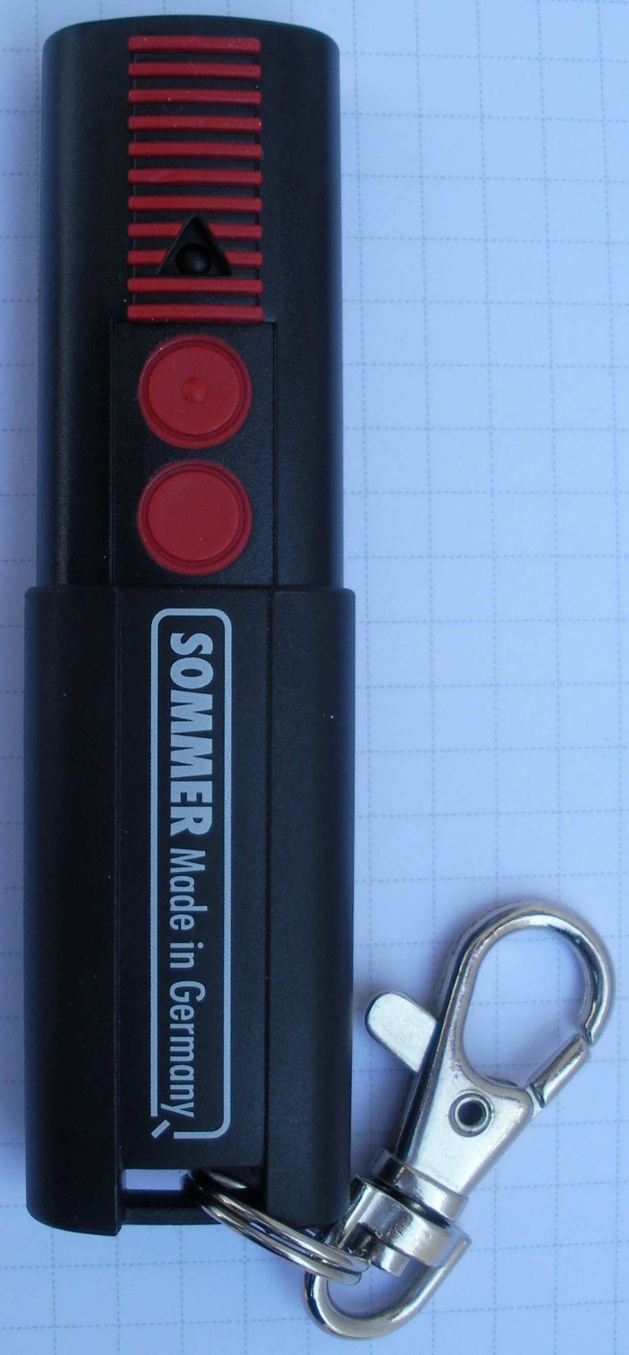
T8C101
Jul 11, 2011Remote Control Transmitter
Equipment Class
DSC - Part 15 Security/Remote Control Transmitter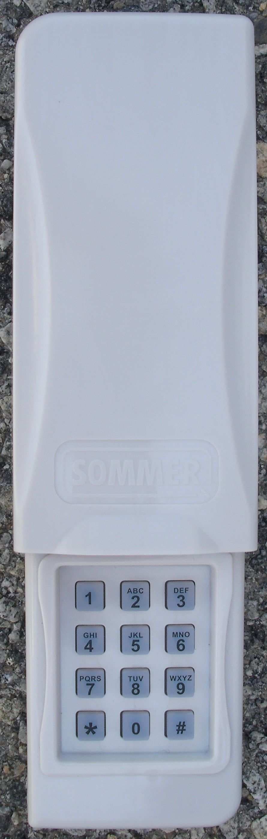
T8C104
Jul 11, 2011Remote Control Transmitter
Equipment Class
DSC - Part 15 Security/Remote Control Transmitter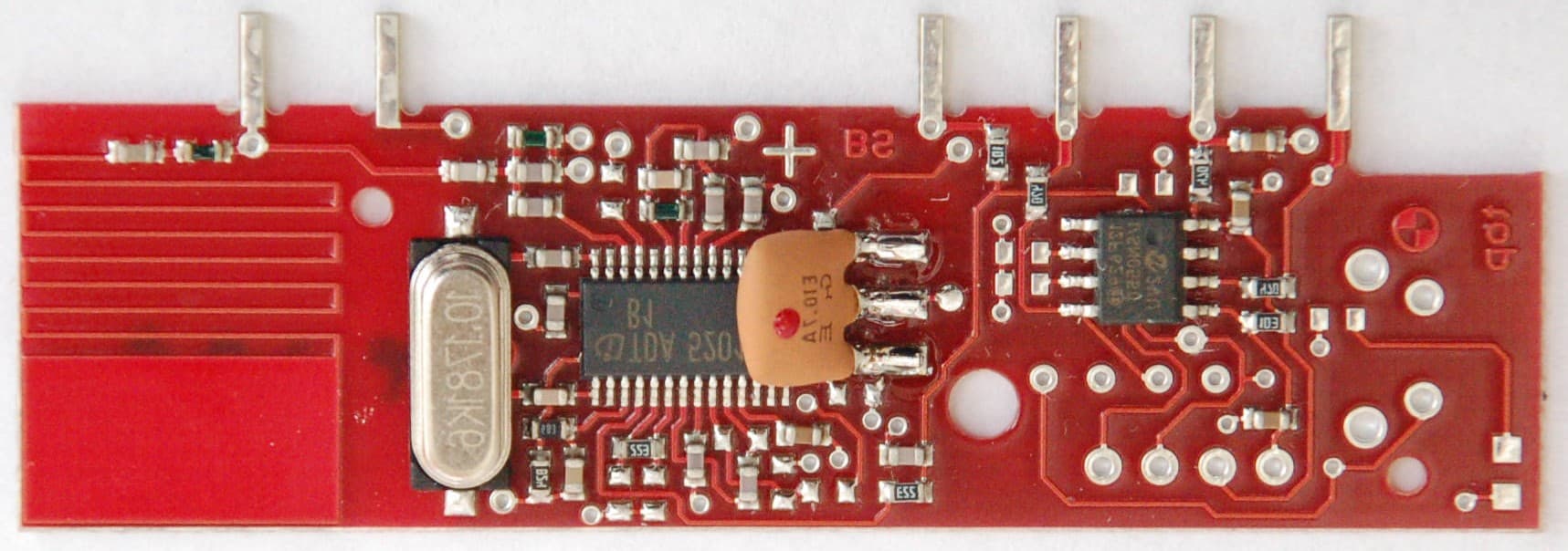
T8C002
Feb 07, 2007Receiver module, e.g. for garage door operator
Equipment Class
CYY - Communications Receiver used w/Pt 15 Transmitter