T8C102Receiver Module, e.g. garage door operator
SOMMER Antriebs- und Funktechnik GmbH
Click to zoom
Application Details
- Equipment Class
- CYY - Communications Receiver used w/Pt 15 Transmitter
- Date of Grant
- Sep 04, 2013
- Application Purpose
- Original Equipment
- Date of Application
- Sep 04, 2013
- Equipment Note
- Receiver Module, e.g. garage door operator
- Frequency Range
- 310.00000000 - 310.00000000
- Country
- Germany
Documents & Files
Document Text
Text extracted from the exhibit documents filed with the FCC. Open a document above to read the original.
Users Manual
2-channel radio receiver - item no. 4798V000 Technical data Radio frequency310 MHz Rated voltage rangeAC/DC 12 - 24 Volt ±20% Temperature range-4 °F - 158 °F max. current consumption with80 mA, DC12 V max. current consumption with175 mA, AC 24 V Output fl oating relay contact Switching capacity (Ohmic load)1.0 A, AC/DC 30 V Area of applicationdry, rooms enclosed on all sides Storage locations112 radio codes Dimensions109 x 40 x 32 mm / 4,29" x 1,57" x 1,26" Weightc. 55 g Program modemanual via learn button. Operating modeInching ModulationAM Safety information ►Before working on the radio receiver, ensure it has been disconnected from the main power supply and it cannot be inadvertently switched back on. ►For a safe operation, ensure the local safety regulations and those pertinent to this equipment are followed! ►Safeguard the power supply and the outputs of the radio receiver from malfunctions (e.g.: short circuit). Use appropriate fuses for this. Intended use ►Use remote control for systems that pose an accident risk only if the user actually has direct visual contact! ►It is not permitted to use remote control for equipment and systems with an increased accident risk (e.g. crane systems)! ►The remote control may only be used for equipment and/or systems where interference in the transmitter or receiver does not pose a risk to humans, animals or objects, or where the risk is covered by other safety devices. ►The operator is not protected from faults due to other telecommunications equipment or devices (e.g. radio systems, which are being operated properly in the same frequency range). ►Maximum cable length on all connections – 3 m / 10 ft. ►After a voltage drop (e.g. power cut), the radio receiver sets all the outputs to OFF. You must switch a controlled alarm system back on again or ensure a buffer battery after a voltage drop or power failure. Connections A.Floating relay contacts, allowed cable cross-section max. 1.5 mm² / AWG 16 Power supply A.1AC/DC 12 - 24 Volt A.2Ground Relay contact -> channel 1 A.3 A.4 Relay contact -> channel 2 A.5 A.6 B.Button: Sets the radio receiver to program, delete or normal mode. D.LEDs: Indicate which channel has been selected and which mode is enabled. D.1Relay contact -> channel 1 D.2Relay contact -> channel 2 1. Attach the External Receiver to the outside of the control housing of the SOMMER garage door opener. 2. Connect terminal 1 on the External Receiver to Terminal 1 on the SOMMER/Direct Drive opener. Connect Terminals 2 and 2 in the same manner. 3. Connect Terminals 3 and 4 on the SOMMER External Receiver to the wall button connection for the other brand opener. (also see diagram and directions on page 2 for additional information) Programming the hand-held remote control manually • To program the hand-held remote control, press the learn button (B). Press the learn button (B) several times in order to select the required channel. 1. Press the learn button (B). 1x -> channel 1 (LED D.1 lights up) 2x -> channel 2 (LED D.2 lights up) 2. Press the required hand-held remote control button within 10 seconds. The LED switches off, programming procedure concluded. Deleting the hand-held remote control button from the radio receiver Should a user of a multi-car car garage system move and wish to take his hand-held remote control with him, all the radio codes of the hand- held remote control must be deleted from the radio receiver. Attention! For safety reasons, each button and each button combination must be deleted from the hand-held remote control! 1. Press button (B) and hold it down for 5 seconds until the LED fl ashes (irrespective of channel). 2. Release button (B) – radio receiver is now in delete mode. 3. On the hand-held remote control, press the button for which the code in the radio receiver should be deleted. LED switches off. Deletion procedure concluded. Repeat the process 1 - 3 for all buttons and all button combinations. Deleting the radio channel from the radio receiver 1. Press button (B) on the radio receiver and hold it down. – 1x for channel 1, LED (D.1) lights up. – 2x for channel 2, LED (D.2) lights up. The LED fl ashes after 5 seconds. The LED lights up after a further 10 seconds. 2. Release button (B) – deletion procedure concluded. Deleting the radio receiver ́s memory If a hand-held remote control is lost, for safety reasons all channels on the radio receiver must be deleted! Then the radio receiver must be reprogrammed for all hand-held remote controls. 1. Press button (B) on the radio receiver and hold it down. The LED fl ashes after 5 seconds. The LED lights up after a further 10 seconds. All LEDs light up after a further 25 seconds. 2. Release button (B) – deletion procedure concluded. Troubleshooting LED (D.1 and D.2) fl ashing: It is being attempted to occupy more than 112 storage locations on the radio receiver. LED (D.1 or D.2) fl ashing: Programming mode, radio receiver is waiting for a radio code from a hand-held remote control. HomeLink This device is compatible to the HomeLink system from version 3 Information This device complies with Part 15 of the FCC Rules. Operation is subject to the following two conditions: (1) this device may not cause harmful interference, and (2) this device must accept any interference received, including interference that may cause undesired operation. No modifi cations to this device are allowed. The operating license expires if modifi cations are performed on this device that are not described in this manual or authorized by the manufacturer. English Español rev. November 2012 1 - 2 3 - 4 5 - 6 SOMMER External Receiver SOMMER / Direct Drive opener 6 - 5 4 - 3 2 - 1 External receiver works with12-24v AC or DC 1. Attach the External Receiver to the outside of the control housing of the SOMMER garage door opener. 2. Connect terminal 1 on the External Receiver to Terminal 1 on the SOMMER/Direct Drive opener. Connect Terminals 2 and 2 in the same manner.3. Connect Terminals 3 a…
Text truncated - open the document above for the full version.
Cover Letter(s)
Sommer Antriebs- und Funktechnik GmbH Address: Hans-Böckler-Straße 21-27 D-73230 Kirchheim/Teck Phone: +49 (0)7021/ 8001-412 Fax: +49 (0)7021/ 8001-403 Manufacturer of radiocontrolled operators for garage doors with accessories Your ref. Your message from Our ref. baa Date 22.08.2013 page 1 of 1 Department : Entwicklung / (Development) / Badran, Ali E-Mail : [email protected] http://www.sommer.eu Sommer Antriebs- und Funktechnik GmbH, Hans-Böckler-Str. 21-27, D-73230 Kirchheim/Teck Gentlemen: This letter is to comply with Sections 0.457 and 0.459 pertaining to confidential material. SOMMER Antriebs- u. Funktechnik GmbH would like the following documents regarding this submission for FCC ID: T8C102 to be kept confidential: 04_OpDes.pdf _BlkDia.pdf: Operational description & Block diagram 05_Schem.pdf: Schematic The above material contains trade secrets or technical data, which would customarily be guarded from competitors. We do not want these documents to be accessible to the general public. Sincerely, A. Badran
External Photos
Type RM02-310-2 / RM02-310-2-C FCC ID T8C102 Abteilung: Entwicklung / (Development) erstellt am: 22.08.2013 erstellt von: Badran, Ali Seite von 1 7 External Photos: EUT: receiver module RM02-310-2 front view: rear view: Type RM02-310-2 / RM02-310-2-C FCC ID T8C102 Abteilung: Entwicklung / (Development) erstellt am: 22.08.2013 erstellt von: Badran, Ali Seite von 2 7 EUT: receiver module RM02-310-2-C front view: rear view: Type RM02-310-2 / RM02-310-2-C FCC ID T8C102 Abteilung: Entwicklung / (Development) erstellt am: 22.08.2013 erstellt von: Badran, Ali Seite von 3 7 Receiver module RM02-310-2 in synoris front view: Type RM02-310-2 / RM02-310-2-C FCC ID T8C102 Abteilung: Entwicklung / (Development) erstellt am: 22.08.2013 erstellt von: Badran, Ali Seite von 4 7 Receiver module RM02-310-2 in synoris rear view: Type RM02-310-2 / RM02-310-2-C FCC ID T8C102 Abteilung: Entwicklung / (Development) erstellt am: 22.08.2013 erstellt von: Badran, Ali Seite von 5 7 Receiver module RM02-310-2-C in Pro 1000 front view: Type RM02-310-2 / RM02-310-2-C FCC ID T8C102 Abteilung: Entwicklung / (Development) erstellt am: 22.08.2013 erstellt von: Badran, Ali Seite von 6 7 Receiver module RM02-310-2-C in Pro 1000 rear view: Type RM02-310-2 / RM02-310-2-C FCC ID T8C102 Abteilung: Entwicklung / (Development) erstellt am: 22.08.2013 erstellt von: Badran, Ali Seite von 7 7 Receiver module in 2-Channel-Receiver RX04-RM02-310-2-C front view: rear view:
ID Label/Location Info
Type RM02-310-2 / RM02-310-2-C FCC ID T8C102 Abteilung: Entwicklung / (Development) erstellt am: 15.08.2013 erstellt von: Schwarz, Dominik Verteiler: Seite von 1 3 Device-Identifier & label information: Label location on synoris: Label information for synoris: Type RM02-310-2 / RM02-310-2-C FCC ID T8C102 Abteilung: Entwicklung / (Development) erstellt am: 15.08.2013 erstellt von: Schwarz, Dominik Verteiler: Seite von 2 3 Label location on Pro 1000: Label information for Pro 1000: Type RM02-310-2 / RM02-310-2-C FCC ID T8C102 Abteilung: Entwicklung / (Development) erstellt am: 15.08.2013 erstellt von: Schwarz, Dominik Verteiler: Seite von 3 3 Label location and information on 2-Channel-Receiver: RX04-RM02-310-2-C:
Internal Photos
Type RM02-310-2 / RM02-310-2-C FCC ID T8C102 Abteilung: Entwicklung / (Development) erstellt am: 22.08.2013 erstellt von: Badran, Ali Verteiler: Seite von 1 8 Internal photos: Receiver module RM02-310-2 in synoris Type RM02-310-2 / RM02-310-2-C FCC ID T8C102 Abteilung: Entwicklung / (Development) erstellt am: 22.08.2013 erstellt von: Badran, Ali Verteiler: Seite von 2 8 Receiver module RM02-310-2 in synoris front view: Type RM02-310-2 / RM02-310-2-C FCC ID T8C102 Abteilung: Entwicklung / (Development) erstellt am: 22.08.2013 erstellt von: Badran, Ali Verteiler: Seite von 3 8 Receiver module RM02-310-2 in synoris rear view: Type RM02-310-2 / RM02-310-2-C FCC ID T8C102 Abteilung: Entwicklung / (Development) erstellt am: 22.08.2013 erstellt von: Badran, Ali Verteiler: Seite von 4 8 Receiver module RM02-310-2-C in Pro 1000 Type RM02-310-2 / RM02-310-2-C FCC ID T8C102 Abteilung: Entwicklung / (Development) erstellt am: 22.08.2013 erstellt von: Badran, Ali Verteiler: Seite von 5 8 Receiver module RM02-310-2-C in Pro 1000 front view: Type RM02-310-2 / RM02-310-2-C FCC ID T8C102 Abteilung: Entwicklung / (Development) erstellt am: 22.08.2013 erstellt von: Badran, Ali Verteiler: Seite von 6 8 Receiver module RM02-310-2-C in Pro 1000 rear view: Type RM02-310-2 / RM02-310-2-C FCC ID T8C102 Abteilung: Entwicklung / (Development) erstellt am: 22.08.2013 erstellt von: Badran, Ali Verteiler: Seite von 7 8 Receiver module in 2-Channel-Receiver RX04-RM02-310-2-C Type RM02-310-2 / RM02-310-2-C FCC ID T8C102 Abteilung: Entwicklung / (Development) erstellt am: 22.08.2013 erstellt von: Badran, Ali Verteiler: Seite von 8 8 Receiver module in 2-Channel-Receiver RX04-RM02-310-2-C front view: rear view:
Test Report
!urrrc- 17 r*. n¿søx PAGE 1 OF 26 TEST REPORT # EMCC-950432.1Y, 2013-08-20 EQUIPMENT UNDER TEST: Trade Name: Radio receiver module 2-channel Type: RM02-310-2 / RM02-310-2-C Serial No: 018043C / 0148662 / 0180438 Equipment Category: Receiver (module) Manufacturer: SOMMER Antriebs- und Funktechnik GmbH Address: Hans-Boeckler-Strasse 21-27 73230 Kirchheim unter Teck Germany Client: SOMMER Antriebs- und Funktechnik GmbH Address: Hans-Boeckler-Strasse 21-27 73230 Kirchheim unter Teck Germany Name for contact purposes: Mr Ali Badran Phone: +497021 8001-412 Fax: +497021 8001-403 Email: [email protected] RELEVANT STANDARD: 47 CFR Part 15 B MEASUREMENT PROCEDURE USED: X n¡¡sl c63.4-2009 n n¡lsl c63.10-2009 n other TEST REPORT PREPARED BY: Zakaria Khalek EMCCONS DR. RASEK GMbH & CO. KG E-Mail: [email protected] TEST PERSONNEL: HEAD OF GROUP: v Zakaria Khalek Wolfgang Doering EMCCons OR. RRSEX GmbH & Co. KG EMC, Radio, Safety and Environmental Tsst¡ng Moggast, Boelwiese I 91320 Ebermannstadt Germany FCC Registration # 878769 lndustry Canada Listing # 3464C s50432_lY Telephone: +49 9194 9016 Telefax: +49 9194 8125 Mail: [email protected] Web: htlp:Í\uww.emcc.de ( oou*r** Akkred itieru ngsstelle D-PL-12067-01-01 Test Report # EMCC-950432.1Y Page 2 of 26 Issue Date: 2013-08-20 Tests of Radio receiver module 2-channel Type RM02-310-2 / RM02-310-2-C to 47 CFR Part 15 B © EMCCons DR. RAŠEK GmbH & Co. KG 2013 950432.1Y CONTENTS Page 1 GENERAL INFORMATION ................................................................................................................................................................... 3 1.1 Purpose .................................................................................................................................................................................. 3 1.2 Limits and Reservations ...................................................................................................................................................... 3 1.3 Test Location ......................................................................................................................................................................... 3 1.4 Manufacturer ......................................................................................................................................................................... 3 1.5 Client ...................................................................................................................................................................................... 4 1.6 Dates and Test Location ...................................................................................................................................................... 4 1.7 Climatic Conditions .............................................................................................................................................................. 4 2 PRODUCT DESCRIPTION .................................................................................................................................................................... 5 2.1 Equipment Under Test (EUT) ............................................................................................................................................... 5 2.2 EUT Peripherals .................................................................................................................................................................... 5 2.3 Mode of Operation During Testing ..................................................................................................................................... 5 2.4 Modifications Required for Compliance ............................................................................................................................ 5 3 TEST RESULTS SUMMARY ................................................................................................................................................................ 6 4 POWER LINE CONDUCTED EMISSIONS TEST ................................................................................................................................. 7 4.1 Regulation ............................................................................................................................................................................. 7 4.2 Test Equipment ..................................................................................................................................................................... 7 4.3 Test Procedures .................................................................................................................................................................... 7 4.4 Test Results ........................................................................................................................................................................... 8 5 RADIATED EMISSIONS ...................................................................................................................................................................... 13 5.1 Regulation ........................................................................................................................................................................... 13 5.2 Test Equipment ................................................................................................................................................................... 13 5.3 Test Procedures .................................................................................................................................................................. 14 5.4 Field Strength Calculation ................................................................................................................................................. 14 5.5 Test Results Prescan ..............................................................................................…
Text truncated - open the document above for the full version.
Test Setup Photos
Test Report # EMCC-950432.1Y Page 19 of 26 Issue Date: 2013-08-20 Tests of Radio receiver module 2-channel Type RM02-310-2 / RM02-310-2-C to 47 CFR Part 15 B © EMCCons DR. RAŠEK GmbH & Co. KG 2013 950432.1Y APPENDIX 1 - PHOTOGRAPHS OF TEST SETUP Test setup #1 Conducted measurement Radiated measurement Close-up view Labelling receiver module Test Report # EMCC-950432.1Y Page 20 of 26 Issue Date: 2013-08-20 Tests of Radio receiver module 2-channel Type RM02-310-2 / RM02-310-2-C to 47 CFR Part 15 B © EMCCons DR. RAŠEK GmbH & Co. KG 2013 950432.1Y Test setup #2 Conducted measurement Radiated measurement Close-up view test position 1 Close-up view test position 2 Labelling receiver module Test Report # EMCC-950432.1Y Page 21 of 26 Issue Date: 2013-08-20 Tests of Radio receiver module 2-channel Type RM02-310-2 / RM02-310-2-C to 47 CFR Part 15 B © EMCCons DR. RAŠEK GmbH & Co. KG 2013 950432.1Y Test setup #3 Conducted measurement Radiated measurement Close-up view test position 1 Close-up view test position 2 Labelling Power supply used for testing
Contact Information
Applicant
Jochen Lude
Test Firm
EMCCons DR. RASEK GmbH & Co. KGReinhard Sauerchell
Technical Specifications
| # | Rule Parts | Frequency Range | Power Output |
|---|---|---|---|
| 1 | 15B | 310 MHz - 310 MHz | - |
Other Applications from SOMMER Antriebs- und Funktechnik GmbH
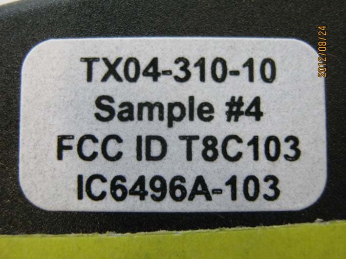
T8C103
Nov 06, 2012Remote Control Transmitter
Equipment Class
DSC - Part 15 Security/Remote Control Transmitter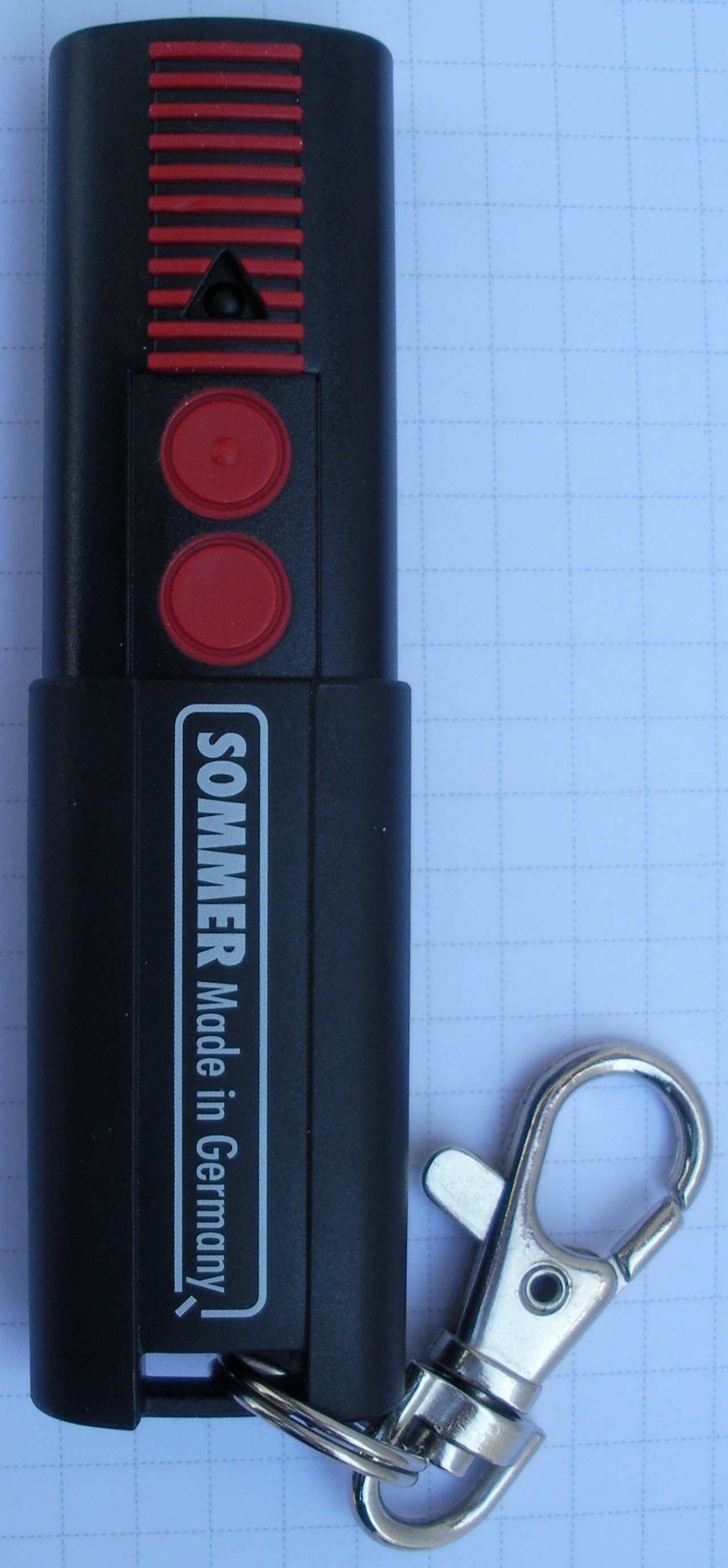
T8C101
Jul 11, 2011Remote Control Transmitter
Equipment Class
DSC - Part 15 Security/Remote Control Transmitter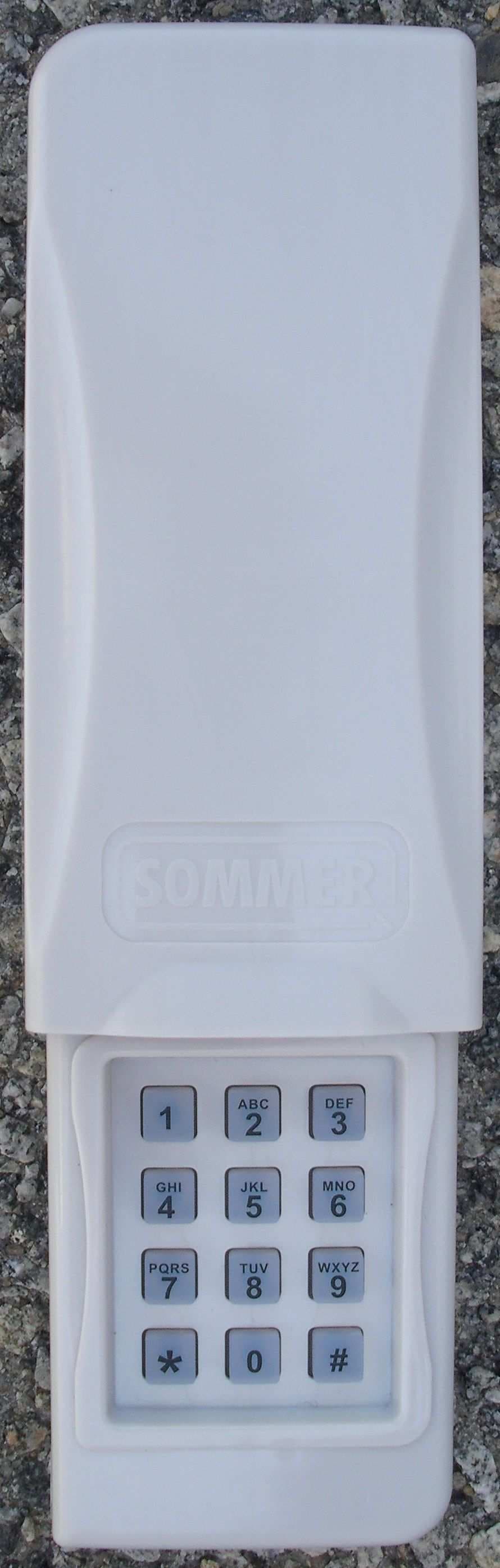
T8C104
Jul 11, 2011Remote Control Transmitter
Equipment Class
DSC - Part 15 Security/Remote Control Transmitter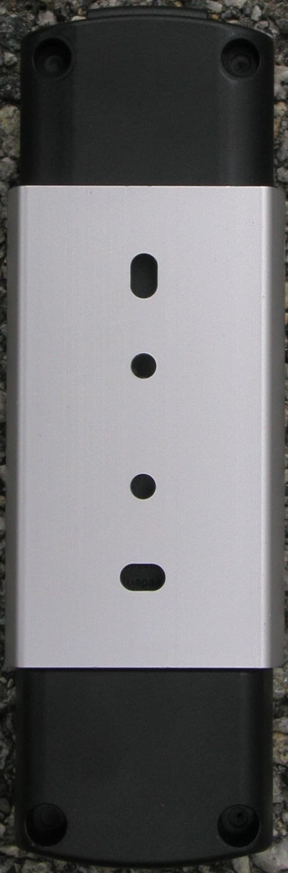
T8C003
Oct 30, 2007Telecody - Keypad Transmitter
Equipment Class
DSC - Part 15 Security/Remote Control Transmitter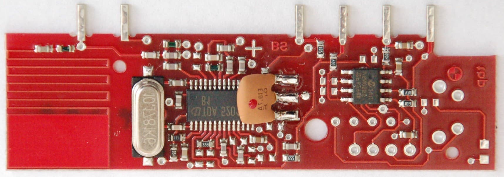
T8C002
Feb 07, 2007Receiver module, e.g. for garage door operator
Equipment Class
CYY - Communications Receiver used w/Pt 15 Transmitter