T8C101Remote Control Transmitter
SOMMER Antriebs- und Funktechnik GmbH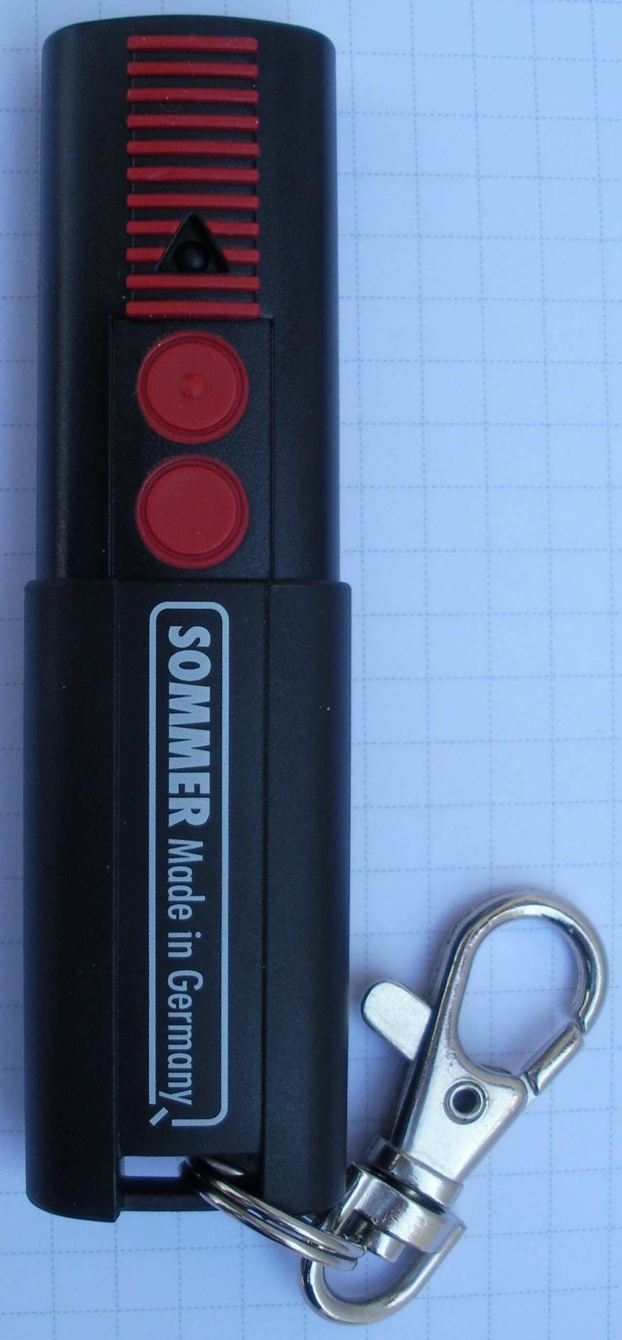
Click to zoom
Application Details
- Equipment Class
- DSC - Part 15 Security/Remote Control Transmitter
- Date of Grant
- Jul 11, 2011
- Application Purpose
- Original Equipment
- Date of Application
- Jul 11, 2011
- Equipment Note
- Remote Control Transmitter
- Frequency Range
- 310.00000000 - 310.00000000
- Country
- Germany
Documents & Files
Document Text
Text extracted from the exhibit documents filed with the FCC. Open a document above to read the original.
Users Manual
4055V000-4055V001-4055V002-152011-0-OCE_Rev US 4-button transmitter WARNING There is a possible risk of injury or even the risk of death if important safety information is not observed and complied with. Observe and comply with all information in this manual and additionally all information in the manual of the drive. You must also inform all additional users about this manual. No modifications to this device are allowed. The operating license expires if modi- fications are performed on this device that are not described in this manual or authorized by the manufacturer. This device complies with Part 15 of the FCC Rules. Operation is subject to the following two conditions: (1) this device may not cause harmful interference, and (2) this device must accept any interference received, including inter- ference that may cause undesired operation. Mode of operation Using this radio remote control, an electrically powered drive can be controlled for opening and closing sectional doors or swinging doors. Technical specifications Radio frequency 310 MHz Temperature range 14 °F to +158 °F (–10 °C to +70 °C) Range Approx. 100 ft (30 m), depending on surrounding conditions Current consumption Approx. 10 mA Battery (supplied) Type CR 2032, 3 V Dimensions (slid together) 3 7/16” x 15/16” x 11/16” (87 x 24 x 17 mm) Weight Approx. 30 g (including battery) Program the transmitter In order to open, close or stop the opener using the transmitter, the opener has to “learn” the code first. The radio code of the transmitter is transmitted to the receiver (inside the control housing). Radio Po we r Sta tus Safety Command Reset Lear nLear n 2 1 14 15 16 Radio Po we r St at us Safety Command Reset Lear n Lear n 13 3 4 5 6 2 1 1 ►Plug in the power plug into the power outlet or ►Switch on the electrical supply for a permanent wiring connection (switch on the circuit breaker or fuse). When the opener is first connected to the mains supply, the opener lighting blinks. Learning the radio code ►Press the learn button (1) once on the control housing. –The LED (Radio) is solid. ►Press a desired transmitter but- ton (2). –The LED (Radio) flashes briefly. –If the LED (Radio) lights up for a second, the transmitter has been learned. –If the LED (Radio) blinks three times, all buttons/storage loca- tions are already occupied. Programming additional transmitters. Repeat the above steps. A maximum of 20 button/storage locations for each radio receiver are available. If no radio code is received within 10 seconds, the learning process is inter- rupted and has to be started again if nece ssary. Light function In order to switch the light on the opener on or off separately using the transmitter, a second transmitter but- ton function has to be “learned in”. Radio Po we r Sta tus Safety Command Reset Lear nLear n 2 1 14 15 16 Radi o Po we r St at us Safety Command Reset Lear n Lear n 13 3 4 5 6 2 1 1 ►Press the learn button (1) on the control housing two times. –The LED (Radio) blinks briefly. ►Press the desired transmitter but- ton (2). –When the LED (Radio) lights up for a second, the transmit- ter has been learned. –If the LED (Radio) blinks three times, all buttons/storage loca- tions are already occupied. Other functions Depending on the DIP switch settings, other functions such as “partial open- ing” or “defined operation” can be “learned in” for a second transmitter button in the same way. See chapter “Settings”. Aborting the learn process 2 1 14 15 16 Radio Po we r St at us Safety Command Reset Lear n Lear n 13 3 4 5 6 Radio Po we r Sta tus Safety Command Reset Lear nLear n 11 ►Press the learn button (1) on the controller housing until no LED lights up. If no radio code is received within 10 seconds, the learning pro- cess is interrupted and has to be started again if necessary. Deleting a previously learned radio code 2 1 14 15 16 Radi o Po we r St at us Safety Command Reset Lear n Lear n 13 3 4 5 6 Radio Po we r Sta tus Safety Command Reset Lear nLear n 11 ►Press the learn button (1) on the control housing for at least five seconds until the LED (Radio) blinks slowly. ►Press the desired transmitter button. –The LED (Radio) lights up for one second. –When the LED (Radio) turns off, the radio code of this trans- mitter button is deleted. Deleting all previously learned radio codes 2 1 14 15 16 Radi o Po we r St at us Safety Command Reset Lear n Lear n 13 3 4 5 6 Radio Po we r Sta tus Safety Command Reset Lear nLear n 11 ►Press the learn button (1) and hold for approx. 60 sec. until the LED (Radio) turns off. –All radio codes have been deleted. Operation WARNING There is a possible risk of injury or death if you do not observe and comply with the following information. Observe and comply with all listed instructions before operating. Only operate the transmitter when you have direct line of sight to the door and no persons or objects are located in the area of the door’s motion. Only pass through the garage open- ing after the garage door has opened completely. Store the transmitter in a safe place to prevent unwanted operation for example, by children. Do not use the transmitter in areas with sensitive radio communications or systems (for example: airports, hospitals). The remote has an integrated clip so that you can carry it as you would a pen in your shirt pocket for example. When closed, the transmitter is pro- tected by a stainless steel case to prevent an unintended operation. ►To access the buttons, slide the transmitter body (1) out of the stainless steel case (2). There are positions for each button (a total of 4 buttons). ►To close the transmitter body (1), slide it back into the stainless steel case (2) up to the stop position. Opening, closing, and stopping the door In order to operate the opener using the transmitter, this opener function first has to “learn in” the code of a par- ticular transmitter. See “Program the transmitter”. ►To open and close the door, press the corresponding button on the transmitte…
Text truncated - open the document above for the full version.
Cover Letter(s)
Sommer Antriebs- und Funktechnik GmbH Address: Hans-Böckler-Straße 21-27 D-73230 Kirchheim/Teck Phone: +49 (0)7021/ 8001-411 Fax: +49 (0)7021/ 8001-403 Manufacturer of radiocontrolled operators for garage doors with accessories Your ref. Your message from Our ref. dsz Date 28.06.2011 page 1 of 1 Department : Entwicklung / (Development) / Schwarz, Dominik E-Mail : [email protected] http://www.sommer.eu Sommer Antriebs- und Funktechnik GmbH, Hans-Böckler-Str. 21-27, D-73230 Kirchheim/Teck Gentlemen: This letter is to comply with Sections 0.457 and 0.459 pertaining to confidential material. SOMMER Antriebs- u. Funktechnik GmbH would like the following documents regarding this submission for FCC ID: T8C101 to be kept confidential: 04_OpDes_BlkDia.pdf 05_Schem.pdf The above material contains trade secrets or technical data, which would customarily be guarded from competitors. We do not want these documents to be accessible to the general public. Sincerely,
External Photos
Type TX03-310-4 FCC ID T8C101 / IC: 6496A-101 Abteilung: Entwicklung / (Development) erstellt am: 28.06.2011 erstellt von: Schwarz, Dominik Verteiler: Seite von 1 5 TX03-310-x: Transmitter family overview The PCB of the 4-channel transmitter TX03-310-4, which was measured according to the FCC and IC rules, shall be used in 3 different housings. 4-channel transmitter TX03-310-4: The measured product. 2-channel transmitter TX02-310-2: Portable transmitter with the same housing as the 4-channel, but the sliding metal part is replaced by a fixed plastic part. The same PCB is used with the following differences in component placement: - button S3 and S4 are not mounted (n.m.) - programming connector X4 is not mounted. 3-channel transmitter TX02-310-3: Wall-mount housing with the same PCB with the following differences in component placement: - Button S5 is mounted instead of S2 at another position, button S3 is not mounted. - The battery holder is not mounted. Type TX03-310-4 FCC ID T8C101 / IC: 6496A-101 Abteilung: Entwicklung / (Development) erstellt am: 28.06.2011 erstellt von: Schwarz, Dominik Verteiler: Seite von 2 5 TX03-310-4: 4-channel transmitter Front view Rear View Type TX03-310-4 FCC ID T8C101 / IC: 6496A-101 Abteilung: Entwicklung / (Development) erstellt am: 28.06.2011 erstellt von: Schwarz, Dominik Verteiler: Seite von 3 5 TX03-310-4: 2-channel transmitter This transmitter does not have a moving part. The lower part of the housing is only removed for replacing the battery. Model TX03-310-4 Model TX03-310-2 Type TX03-310-4 FCC ID T8C101 / IC: 6496A-101 Abteilung: Entwicklung / (Development) erstellt am: 28.06.2011 erstellt von: Schwarz, Dominik Verteiler: Seite von 4 5 TX03-310-3: 3-channel transmitter Front view Rear view Internal View Type TX03-310-4 FCC ID T8C101 / IC: 6496A-101 Abteilung: Entwicklung / (Development) erstellt am: 28.06.2011 erstellt von: Schwarz, Dominik Verteiler: Seite von 5 5 The device identifier is on the rear side of the device engraved into the mould of the plastic part. Picture of the device identifier: Rear view of 2 button transmitter Rear view 4 button transmitter
ID Label/Location Info
Type TX03-310-4 FCC ID T8C101 / IC: 6496A-101 Abteilung: Entwicklung / (Development) erstellt am: 04.07.2011 erstellt von: Schwarz, Dominik Verteiler: Seite von 1 1 TX03-310-x: Label: TX03-310-4:Label: TX03-310-4: Label location on rear side of device: TX03-310-2: Label: TX03-310-2: Label location on rear side of device: Type TX03-310-4 FCC ID T8C101 / IC: 6496A-101 Abteilung: Entwicklung / (Development) erstellt am: 04.07.2011 erstellt von: Schwarz, Dominik Verteiler: Seite von 2 2 TX03-310-3: TX03-310-3: Label location on rear side of device:
Internal Photos
Type TX03-310-4 FCC ID T8C001 / IC: 6496A-001 Abteilung: Entwicklung / (Development) erstellt am: 28.06.2011 erstellt von: Schwarz, Dominik Verteiler: Seite von 1 3 TX03-310-x: Transmitter family overview The PCB of the 4-channel transmitter TX03-310-4, which was measured according to the FCC and IC rules, shall be used in 3 different housings. 4-channel transmitter TX03-310-4: The measured product. 2-channel transmitter TX02-310-2: Portable transmitter with the same housing as the 4-channel, but the sliding metal part is replaced by a fixed plastic part. The same PCB is used with the following differences in component placement: - button S3 and S4 are not mounted (n.m.) - programming connector X4 is not mounted. 3-channel transmitter TX02-310-3: Wall-mount housing with the same PCB with the following differences in component placement: - Button S5 is mounted instead of S2 at another position, button S3 is not mounted. - The battery holder is not mounted. Type TX03-310-4 FCC ID T8C001 / IC: 6496A-001 Abteilung: Entwicklung / (Development) erstellt am: 28.06.2011 erstellt von: Schwarz, Dominik Verteiler: Seite von 2 3 Front view: TX03-310-4 TX03-310-2 TX03-310-3 4-channel version 2-channel version 3-channel version Type TX03-310-4 FCC ID T8C001 / IC: 6496A-001 Abteilung: Entwicklung / (Development) erstellt am: 28.06.2011 erstellt von: Schwarz, Dominik Verteiler: Seite von 3 3 Rear view: TX03-310-4 TX03-310-2 TX03-310-3 4-channel version 2-channel version 3-channel version
Test Report
FCC-ID: T8C101 Test Report #EMCC-950432.1TAA Page 2 of 26 Issue Date: 2011-04-13 Test of SOMMER 4 Button Transmitter, AM 310 MHz Model TX03-310-4 to 47 CFR Part 15C and RSS-210 Issue 8 (2010-12) © EMCCons DR. RAŠEK GmbH & Co. KG 2011 950432.1TAA CONTENTS Page 1 GENERAL INFORMATION ................................................................................................................................................................... 3 1.1 Purpose .................................................................................................................................................................................. 3 1.2 Limits and Reservations ...................................................................................................................................................... 3 1.3 Test Location ......................................................................................................................................................................... 3 1.4 Manufacturer ......................................................................................................................................................................... 3 1.5 Dates and Test Location ...................................................................................................................................................... 4 1.6 Ordering Information ............................................................................................................................................................ 4 1.7 Climatic Conditions .............................................................................................................................................................. 4 2 PRODUCT DESCRIPTION .................................................................................................................................................................... 5 2.1 Equipment Under Test (EUT) ............................................................................................................................................... 5 2.2 EUT Peripherals .................................................................................................................................................................... 5 2.3 Mode of Operation During Testing ..................................................................................................................................... 5 2.4 Modifications Required for Compliance ............................................................................................................................ 5 3 TEST RESULTS SUMMARY ................................................................................................................................................................ 6 4 ANTENNA REQUIREMENT .................................................................................................................................................................. 7 4.1 Regulation ............................................................................................................................................................................. 7 4.2 Result ..................................................................................................................................................................................... 7 5 CONDUCTED EMISSIONS TEST ......................................................................................................................................................... 8 5.1 Regulation ............................................................................................................................................................................. 8 5.2 Test Equipment ..................................................................................................................................................................... 8 5.3 Test Procedures .................................................................................................................................................................... 8 5.4 Test Results ........................................................................................................................................................................... 8 6 RADIATED EMISSIONS TESTS ........................................................................................................................................................... 9 6.1 Regulation ............................................................................................................................................................................. 9 6.2 Test Equipment ................................................................................................................................................................... 11 6.3 Test Procedures .................................................................................................................................................................. 12 6.4 Calculation of Field Strength Limits ................................................................................................................................. 13 6.5 Calculation of Average Correction Factor ....................................................................................................................... 13 6.6 Field Strength Calculation ................................................................................................................................................. 13 6.7 Test Results ......................................................................................................................................................................... 15 6.7.1 Duty Cycle .................................................................................................................................................................... 16 6.7.2 Magne…
Text truncated - open the document above for the full version.
Test Setup Photos
FCC ID: T8C101 Telephone: +49 9194 9016 Telefax: +49 9194 8125 Mail: [email protected] Web: http://www.emcc.de EMCCons DR. RAŠEK GmbH & Co. KG Moggast, Boelwiese 8 91320 Ebermannstadt Germany FCC Registration #878769 950432.1TAA_Annex1 Page 1 of 4 ANNEX 1 TO TEST REPORT # EMCC-950432.1TAA, 2011-04-13 PHOTOGRAPHS OF TEST SETUPS EQUIPMENT UNDER TEST: Trade Name: 4 Button Transmitter, AM 310 MHz Model: TX03-310-4 Serial No: FFFFF2 Equipment Category: Transmitter Manufacturer: SOMMER Antriebs- und Funktechnik GmbH Address: Hans-Boeckler-Strasse 21-27 73230 Kirchheim / Teck Germany Phone: +49 7021 8001-0 Fax: +49 7021 8001-403 E-Mail: [email protected] RELEVANT STANDARD(S): 47 CFR Part 15C RSS-210 Issue 8 (2010-12) CONTENTS Page 1 CONDUCTED EMISSIONS TEST ......................................................................................................................................................... 2 1.1 none ....................................................................................................................................................................................... 2 2 RADIATED EMISSIONS TEST ............................................................................................................................................................. 3 2.1 Magnetic field (H-field), f < 30 MHz, EUT horizontal, upright ........................................................................................... 3 2.2 Electric field, f = 30 MHz to 1 GHz, EUT vertical ................................................................................................................ 3 2.3 Electric field, f = 30 MHz to 1 GHz, EUT horizontal, upright ............................................................................................. 4 2.4 Electric field, f > 1 GHz, EUT vertical .................................................................................................................................. 4 FCC-ID: T8C101 Annex 1 to Test Report #EMCC-950432.1TAA Page 2 of 4 Issue Date: 2011-04-13 Test of SOMMER 4 Button Transmitter, AM 310 MHz Model TX03-310-4 to 47 CFR Part 15C and RSS-210 Issue 8 (2010-12) © EMCCons DR. RAŠEK GmbH & Co. KG 2011 950432.1TAA_Annex1 1 CONDUCTED EMISSIONS TEST 1.1 none not applicable FCC-ID: T8C101 Annex 1 to Test Report #EMCC-950432.1TAA Page 3 of 4 Issue Date: 2011-04-13 Test of SOMMER 4 Button Transmitter, AM 310 MHz Model TX03-310-4 to 47 CFR Part 15C and RSS-210 Issue 8 (2010-12) © EMCCons DR. RAŠEK GmbH & Co. KG 2011 950432.1TAA_Annex1 2 RADIATED EMISSIONS TEST 2.1 Magnetic field (H-field), f < 30 MHz, EUT horizontal, upright 2.2 Electric field, f = 30 MHz to 1 GHz, EUT vertical FCC-ID: T8C101 Annex 1 to Test Report #EMCC-950432.1TAA Page 4 of 4 Issue Date: 2011-04-13 Test of SOMMER 4 Button Transmitter, AM 310 MHz Model TX03-310-4 to 47 CFR Part 15C and RSS-210 Issue 8 (2010-12) © EMCCons DR. RAŠEK GmbH & Co. KG 2011 950432.1TAA_Annex1 2.3 Electric field, f = 30 MHz to 1 GHz, EUT horizontal, upright 2.4 Electric field, f > 1 GHz, EUT vertical
Contact Information
Applicant
Jochen Lude
Test Firm
EMCCons DR. RASEK GmbH & Co. KGReinhard Sauerchell
Technical Specifications
| # | Rule Parts | Frequency Range | Power Output |
|---|---|---|---|
| 1 | 15.231 | 310 MHz - 310 MHz | - |
Other Applications from SOMMER Antriebs- und Funktechnik GmbH

T8C102
Sep 04, 2013Receiver Module, e.g. garage door operator
Equipment Class
CYY - Communications Receiver used w/Pt 15 Transmitter
T8C103
Nov 06, 2012Remote Control Transmitter
Equipment Class
DSC - Part 15 Security/Remote Control Transmitter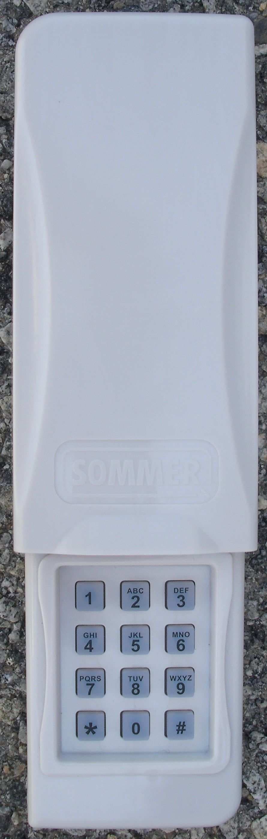
T8C104
Jul 11, 2011Remote Control Transmitter
Equipment Class
DSC - Part 15 Security/Remote Control Transmitter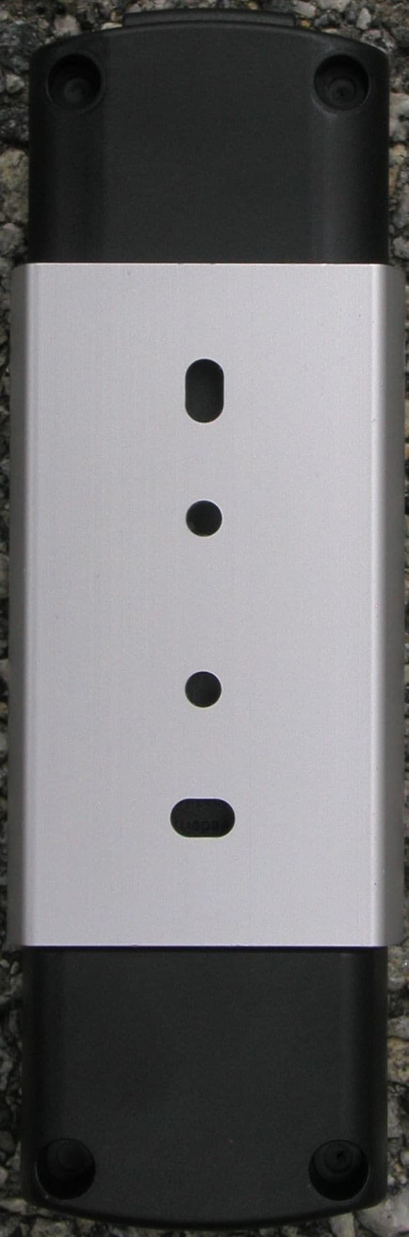
T8C003
Oct 30, 2007Telecody - Keypad Transmitter
Equipment Class
DSC - Part 15 Security/Remote Control Transmitter
T8C002
Feb 07, 2007Receiver module, e.g. for garage door operator
Equipment Class
CYY - Communications Receiver used w/Pt 15 Transmitter