T8H-1SW100Wireless Lock Switch Core
dormakaba USA Inc.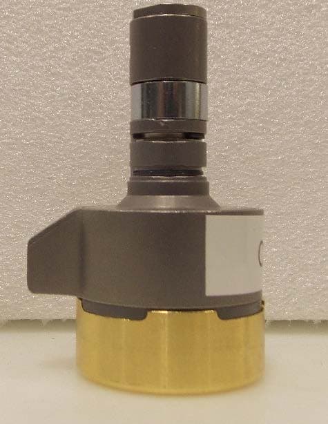
Click to zoom
Application Details
- Equipment Class
- DTS - Digital Transmission System
- Date of Grant
- Feb 26, 2020
- Application Purpose
- Original Equipment
- Date of Application
- Feb 26, 2020
- Equipment Note
- Wireless Lock Switch Core
- Frequency Range
- 2402.00000000 - 2480.00000000
- Company
- dormakaba USA Inc.
- Country
- United States
Documents & Files
Document Text
Text extracted from the exhibit documents filed with the FCC. Open a document above to read the original.
Users Manual
OVERVIEW D C Outside of door A *B *NOTE: The throw member (B) will be reused. E F G Switch™ Core Installation Instructions Insert the control key (D), and rotate 15° clockwise to disengage the control lug. With the control key (D) rotated 15°, remove the core (C) and the throw member (B). If the throw member (B) or the throw pins do not come out with the core (C), leave them in the lock. NOTE: Keep the throw member (B) to reuse. D D C B D 15° 15° DISENGAGE CONTROL LUG 12 D REMOVE CORE AND THROW MEMBER I not included H included BEFORE YOU BEGIN: It is critical to ensure that Switch™ Core is compatible with your Lock Hardware. Please carefully review page 4 and page 5 of this document [Switch™ Core Compatibility Guide] to ensure that you are installing Switch™ Core into appropriate Lock Hardware. A Lever Handle B Throw Member* C Core 7-Pin D Control Key E Switch™ Core F Battery Hex Key 1/16" G Battery Cap H I Battery Removal Tool Compatible Devices: Android™ 5+ iOS: 11.0+ Switch™ Core Installation Instructions T91407_A ©2020 All rights reserved.1/20BEST is a trademark of dormakaba USA Inc. Switch™ Core Installation Instructions Align the throw member (B) with the lock and insert the core (E). Control lug shown retracted NOTE: Insert throw member (B) in core if needed. E B A INSERT CORE 5 CORE ORIENTATION 3 Control lug extended Control lug retracted The hex key (H) should come inserted in the core (E) with the control lug retracted. If so, go to step 5. Otherwise, go to step 4 to retract the control lug. E H RETRACT CONTROL LUG 4 Control lug shown extended Control lug shown retracted Rotate the knob to align the hole in the circuit board with the control access hole in the core (E). Insert the hex key (H). Then gently push and rotate the hex key (H) counterclockwise to retract the control lug. Lobe Hole NOTE: The core (E) must be in installation mode for the hex key (H) to access the control lug. If not, the hex key (H) cannot be rotated. If this is the case, please reference the Switch™ Tech user guide for further instructions. https://support.bestaccess.com/hc/en-us/articles/360036366673 HH E Knob T91407_A ©2020 All rights reserved.2/20BEST is a trademark of dormakaba USA Inc. COMPLETE Switch™ Core Installation Instructions ENGAGE CONTROL LUG 6 INSERT BATTERY 7 WARNING: DO NOT force the battery cap (G) onto the knob as the electrical contacts may bend, rendering the core (E) inoperative. H F G H H E E E E E E EE E Rotate the hex key (H) clockwise to extend and engage the control lug. Remove the hex key (H). Gently pull on the knob to ensure that the core (E) is properly installed. Insert the battery (F) with the positive polarity facing out. Carefully align the battery cap (G) with the knob and gently press until the battery cap (G) SNAPS securely into place. 123 456 + Slide the battery tool (I) over the battery cap (G). Separate the battery tool (I) and the battery cap (G). Remove the battery tool (I) and the battery cap (G). Battery Tool Instructions + I I F G G G G Remove the old battery (F).Insert the new battery (F) with the positive polarity facing out. Carefully align the battery cap (G) with the knob and gently press until it SNAPS securely into place. F COMPLETE I Product Care Instructions CAUTION: Handle the product with care. Do not spray product with foreign materials. CAUTION: Use a clean dry or barely dry damp cloth to clean product. Electrical contact WARNING: DO NOT force the battery cap (G) onto the knob as the electrical contacts may bend, rendering the core (E) inoperative. NOTE: The core can now be initialized in the Switch™ Mobile App. NOTE: Once the new battery is installed, the core may need to charge. T91407_A ©2020 All rights reserved.3/20BEST is a trademark of dormakaba USA Inc. SWITCH™ CORE COMPATIBILITY GUIDE YES NO 1. Is your lock fitted with a 7-pin small format interchangeable core? If your answer is YES, proceed to question 2. If your answer is NO, contact BEST at 1-855-365-2407 or a local authorized reseller. 7-pin SFIC Is my hardware compatible with the Switch™ Core? NOTE: Not recommended for some lock types. Be sure to fully check the functionality of the lock in all states (e.g. push button pressed/deadbolt thrown). To ensure mechanical fit into your application, check an actual Switch™ Core or representative physical sample to ensure the Switch™ Core does not interfere with the normal operation of the Lock Hardware into which it is installed. CORRECT: Face is flush with the hardware. INCORRECT: Face is NOT flush with the hardware. YES NO 2. When installed, does the face of the core fit flush with the hardware? If your answer is YES, proceed to Checking Functional Compatibility on page 5. If your answer is NO, contact BEST at 1-855-365-2407 or a local authorized reseller. WARNING: Installing Switch™ Core into non-compatible hardware can result in improper lock functioning, which could present a risk to users. Please carefully review lock compatibility prior to installation. Improper applications may prevent egress and present a danger. If you are unable to confirm compatibility or have additional questions, please contact BEST at 1-855-365-2407 or a local authorized reseller. T91407_A ©2020 All rights reserved.4/20BEST is a trademark of dormakaba USA Inc. 1. 3. 2. Checking Functional Compatibility DO NOT use Switch™ Core with: If your hardware has an egress lever: Using your existing hardware and an operate key, insert the operate key into the core. Slowly rotate the operate key clockwise through the hardware's full range of operation while simultaneously and frequently checking the egress lever for any issues that could impede free egress. Repeat the procedure while rotating the operate key counterclockwise through the full range or operation. Always ensure that the Switch™ Core does not affect egress. If your hardware has a thumb turn or a pushbutton: Using your existing hardware and an operate key, insert the operate key into the core. Slowly rotate …
Text truncated - open the document above for the full version.
External Photos
www.nemko.com Nemko Canada Inc., a testing laboratory, is accredited by the Standards Council of Canada. The tests included in this report are within the scope of this accreditation External photos.docx; Date: May 2013 SCC Accredited LAB LAB Accrédité CCN TM ONE WORLDOUR APPROVAL External photos 384976-1RADWL Date of issue: Click here to enter a date. Applicant: Dormakaba USA Inc. Product: Electronic Locking Device Model: Model variant: 1SW100 1SW100 FCC ID: ISED Registration number: T8H-1SW100 7713A-1SW100 Section 1: External photos Report reference ID: -1RADWL Page 2 of 7 Section 1. External photos 1.1 Top front view Section 1: External photos Report reference ID: -1RADWL Page 3 of 7 1.2 Top rear view Section 1: External photos Report reference ID: -1RADWL Page 4 of 7 1.3 side view Section 1: External photos Report reference ID: -1RADWL Page 5 of 7 1.4 side view Section 1: External photos Report reference ID: -1RADWL Page 6 of 7 1.5 side view Section 1: External photos Report reference ID: -1RADWL Page 7 of 7 1.6 side view
ID Label/Location Info
Title: SWITCH CORE Label Date: Dec 20 th , 2019 Made By: Sylvain Martel Sheet 1 of 2 CONFIDENTIAL SWITCH CORE Label Title: SWITCH CORE Label Date: Dec 20 th , 2019 Made By: Sylvain Martel Sheet 2 of 2 CONFIDENTIAL 1- Switch Core Label The Switch Core has the FCC and IC numbers printed on the PCB in Silk Screen. Because the PCB is very small, the serial number is written on a 2D bar code label. The Hardware revision is written on this label. The information written on the PCB it is visible inside the Switch Core when the coin-cell battery is removed. This operation can be done by the customer. It was not possible to place this FCC/IC information on the outside of the unit without seriously impacting the appearance of the product. Figure 1- Switch Core Label
Internal Photos
Title: SWITCH CORE INTERNAL PICTURES Date: Dec 19 th , 2019 Made By: Sylvain Martel Sheet 1 of 6 CONFIDENTIAL SWITCH CORE INTERNAL PICTURES Title: SWITCH CORE INTERNAL PICTURES Date: Dec 19 th , 2019 Made By: Sylvain Martel Sheet 2 of 6 CONFIDENTIAL 1- Switch Core Internal Pictures Figure 1- Switch Core Uninstalled Title: SWITCH CORE INTERNAL PICTURES Date: Dec 19 th , 2019 Made By: Sylvain Martel Sheet 3 of 6 CONFIDENTIAL Figure 2- Switch Core Cap Removal with tool (No Battery) Figure 3- Switch Core with Coin Cell Battery Title: SWITCH CORE INTERNAL PICTURES Date: Dec 19 th , 2019 Made By: Sylvain Martel Sheet 4 of 6 CONFIDENTIAL Figure 4- Switch Core with Plastic Ring Removed Figure 5- Switch Core with Front Knob detached from Cylinder Title: SWITCH CORE INTERNAL PICTURES Date: Dec 19 th , 2019 Made By: Sylvain Martel Sheet 5 of 6 CONFIDENTIAL Figure 6- Switch Core with Front Knob Opened Figure 7- Switch Core PCB with Motor Title: SWITCH CORE INTERNAL PICTURES Date: Dec 19 th , 2019 Made By: Sylvain Martel Sheet 6 of 6 CONFIDENTIAL Figure 8- Switch Core PCB
RF Exposure Info
ONE WORLD OUR APPROVAL www.nemko.com KDB 447498 D01 General RF Exposure Guidance v05r02 (February 7, 2014) 1. Declaration of RF exposure compliance for exemption from routine evaluation limits FCC ID: T8H-1SW100 Model number: 1SW100 Manufacturer: dormakaba 4.3.1. Standalone SAR test exclusion considerations: During normal operation, user extremities can come within 20 cm of the internal antenna and therefore product is considered as “Portable”. The 1-g and 10-g SAR test exclusion thresholds for 100 MHz to 6 GHz at Test separation distances ≤ 50 mm are determined by: [(max. power of channel, including tune-up tolerance, mW) ÷ (min. test separation distance, mm)] × [ � 퐹퐹(퐺퐺퐺퐺퐺퐺)] ≤ 3.0 for 1-g SAR and ≤ 7.5 for 10-g extremity SAR, where f(GHz) is the RF channel transmit frequency in GHz Power and distance are rounded to the nearest mW and mm before calculation The result is rounded to one decimal place for comparison The test exclusions are applicable only when the minimum test separation distance is ≤ 50 mm and for transmission frequencies between 100 MHz and 6 GHz. When the minimum test separation distance is < 5 mm, a distance of 5 mm according to 5) in section 4.1 is applied to determine SAR test exclusion Calculation based on the above formula: Separation Distance = 5 mm E.I.R.P. = -20.2 dBm = 0.01 mW Frequency = 2.45 GHz Calculation = (푋푋푋푋푋푋÷5)× √ 푌푌푌푌푌푌 = 0.003 < 3 The calculation is below the threshold, therefore the product exempt from the SAR test requirements 2. Attestation ATTESTATION: I attest that the testing was performed or supervised by me; that the test measurements were made in accordance with the above-mentioned departmental standard(s), and that the radio equipment identified in this application has been subject to all applicable test conditions specified in the departmental standards and all of the requirements of the standards have been met. Signature: Date: February 10, 2020 Name: Yong Huang, Wireless/EMC Specialist FCC SAR Exemption per KDB 447498
Test Report
www.nemko.com Nemko Canada Inc., a testing laboratory, is accredited by the Standards Council of Canada. The tests included in this report are within the scope of this accreditation FCC 15.247 and RSS-247.docx; Date: Apr 2019 MRA il ac SCC Accredited LAB LAB Accrédité CCN TM Choose Scandinavian trust Wireless test report – 384976-1TRFWL Applicant: Dormakaba USA Inc. Product type: Electronic Locking Device Model: Model variant: Switch Core 1SW100 FCC ID: ISED Registration number: T8H-1SW100 7713A-1SW100 Specifications: FCC 47 CFR Part 15 Subpart C, §15.247 Operation in the 902–928 MHz, 2400–2483.5 MHz, and 5725–5850 MHz RSS-247, Issue 2, Feb 2017, Section 5 Digital Transmission Systems (DTSs), Frequency Hopping Systems (FHSs) and Licence-Exempt Local Area Network (LE-LAN) Devices 5) Standard specifications for frequency hopping systems and digital transmission systems operating in the bands 902–928 MHz, 2400–2483.5 MHz and 5725–5850 MHz Date of issue: February 2, 2020 Yong Huang, Wireless/EMC Specialist Tested by Signature David Duchesne, Senior EMC/Wireless Specialist Reviewed by Signature Report reference ID:384976-1TRFWL Applicant: Dormakaba USA Inc. Model: Switch Core Page 2 of 30 Test location(s) Company name Nemko Canada Inc. Site name Montreal Address 292 Labrosse Avenue City Pointe-Claire Province Quebec Postal code H9R 5L8 Country Canada Telephone +1 514 694 2684 Facsimile +1 514 694 3528 Toll free +1 800 563 6336 Website www.nemko.com Site number (3 m SAC) FCC: CA2041; IC: 2040G-5 Limits of responsibility Note that the results contained in this report relate only to the items tested and were obtained in the period between the date of initial receipt of samples and the date of issue of the report. This test report has been completed in accordance with the requirements of ISO/IEC 17025. All results contain in this report are within Nemko Canada’s ISO/IEC 17025 accreditation. Copyright notification Nemko Canada Inc. authorizes the applicant to reproduce this report provided it is reproduced in its entirety and for use by the company’s employees only. Any use which a third party makes of this report, or any reliance on or decisions to be made based on it, are the responsibility of such third parties. Nemko Canada Inc. accepts no responsibility for damages, if any, suffered by any third party as a result of decisions made or actions based on this report. © Nemko Canada Inc. Report reference ID:384976-1TRFWL Applicant: Dormakaba USA Inc. Model: Switch Core Page 3 of 30 Table of contents Table of contents .......................................................................................................................................................................................................... 3 Section 1. Report summary ................................................................................................................................................................................. 4 1.1 Applicant and manufacturer .................................................................................................................................................................................... 4 1.2 Test specifications .................................................................................................................................................................................................... 4 1.3 Test methods ............................................................................................................................................................................................................ 4 1.4 Statement of compliance ......................................................................................................................................................................................... 4 1.5 Exclusions ................................................................................................................................................................................................................. 4 1.6 Test report revision history ...................................................................................................................................................................................... 4 Section 2. Summary of test results ....................................................................................................................................................................... 5 2.1 FCC Part 15 Subpart C, general requirements test results ........................................................................................................................................ 5 2.2 FCC Part 15 Subpart C, intentional radiators test results for digital transmission systems (DTS) ............................................................................. 5 2.3 ISED RSS-Gen, Issue 5, test results............................................................................................................................................................................ 5 2.4 ISED RSS-247, Issue 2, test results for digital transmission systems (DTS) ................................................................................................................ 5 Section 3. Equipment under test (EUT) details ..................................................................................................................................................... 6 3.1 Sample information .................................................................................................................................................................................................. 6 3.2 EUT information ....................................................................................................................................................................................................... 6 3.3 Technical information ..................................................…
Text truncated - open the document above for the full version.
Test Setup Photos
www.nemko.com setup photos.docx; Date: May 2013 ONE WORLDOUR APPROVAL Setup photos 384976RADWL Date of issue: Click here to enter a date. Applicant: Dormakaba USA Inc. Product type: Electronic Locking Device Model: Model variant: 1SW100 1SW100 FCC ID: ISED Registration number: T8H-1SW100 7713A-1SW100 Section 1: setup photos Report reference ID Page 2 of 3 Section 1. Setup photos 1.1 Radiated Front view Section 1: setup photos Report reference ID Page 3 of 3 1.2 Radiated back view
Contact Information
Applicant
Arthur James Croone(Senior Compliance Engineer)
Test Firm
Nemko Canada Inc. (Montreal)Charles Neal
Technical Specifications
| # | Rule Parts | Frequency Range | Power Output |
|---|---|---|---|
| 1 | 15C | 2.40 GHz - 2.48 GHz | 8.50 µW |
Other Applications from dormakaba USA Inc.
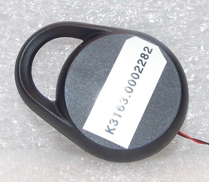
T8H-1SWFOB
Feb 20, 2020Wireless lock FOB
Equipment Class
DTS - Digital Transmission System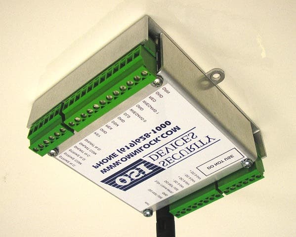
T8H-SDC2K
Mar 06, 2008Single Door Controller
Equipment Class
DTS - Digital Transmission System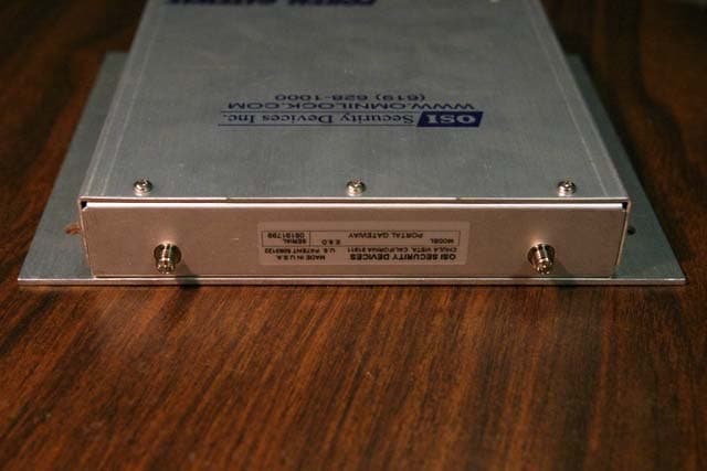
T8H-PG16
Jun 14, 2006Wireless Access Management System Portal Gateway
Equipment Class
DTS - Digital Transmission System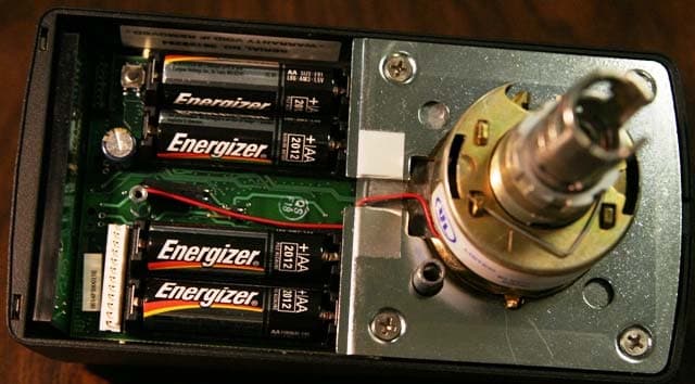
T8H-W2000
Jun 14, 2006Wireless Access Management System Reader
Equipment Class
DTS - Digital Transmission System