T8H-W2000Wireless Access Management System Reader
dormakaba USA Inc.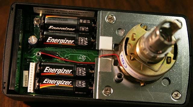
Click to zoom
Application Details
- Equipment Class
- DTS - Digital Transmission System
- Date of Grant
- Jun 14, 2006
- Application Purpose
- Original Equipment
- Date of Application
- Jun 14, 2006
- Equipment Note
- Wireless Access Management System Reader
- Frequency Range
- 2400.00000000 - 2483.50000000
- Company
- dormakaba USA Inc.
- Country
- United States
Documents & Files
Document Text
Text extracted from the exhibit documents filed with the FCC. Open a document above to read the original.
Users Manual
9-2 REMOVING OUTSIDE LEVER WITH INTERCHAN- GEABLE (I.C.) CORE a. Insert the control Key into the I.C. Core and ro tate it 15° clockwise. Pull on the Key to remove the I.C. Core. Be sure that the I.C. Tailpiece is removed wi th the Core. b. Ensure that the Retaining Ring and the Anti-Pick Plate are aligned with the Lever Catch as shown. c. Insert an awl or a small screwdriver through the I.C. Outside Lever and into the slot in the Anti-Pick Plate. Depress the Lever Catch toward the Door Hinge and slide the I.C. Outside Lever from the Spindle. SECURITY D E V I C E S OMNILOC K TWISTED PAIR SWITCH SECTION 6: INSTALL THE STRIKE a. Mark the location of the Latch Bolt on the Door Fra me. b. Center the Strike over the Latch Bolt Mark and, usi ng the Strike as a template, mark the Frame. c. Using the Strike Box as a template, mark the Frame. d. Mortise the Frame to accept the Strike and Strike B ox. e. Install the Strike Box and the Strike and secure wi th the Screws. SECTION 7: PROGRAM THE LOCKSET IMPORTANT: To avoid unauthorized access, it is important to pr ogram a new Programmer ID . Refer to the OMNILOCK Administrator’s Guide for programming instructions. If the System has been installed on a door before the required programming information is available, and your system has a keypad, the access Level may be s et to Unlocked as follows: a. Enter the Default Manager ID 2222 , at the keypad, the green light will flash. b. Press 2 , the green light will flash. c. Press and hold the CL key until the green light flashes four times. (The light will flash once when the CL key is pressed, continue to hold the key until the light flashes th ree more times.) d. The System will remain in the Unlocked mode. SECTION 8: INTERCHANGEABLE CORE 8-1 INTERCHANGEABLE (I.C.) CORE AND TAILPIECE INSTRUCTIONS FOR ARROW I.C. CORES Be certain to use the correct Tailpiece with the Co re. Six-Pin Cores use only the “L6” Tailpiece and Seven-Pin Cores use only the “L7” Tailpiece. SECTION 9: REMOVAL OF LEVERS 9-1 REMOVING OUTSIDE LEVER WITH STANDARD CYLINDER a. Insert the Key into the Cylinder and turn 45° clockwise. b. Depress the Lever Catch through the hole in the Outside Lever by using the Push Pin provided or another suitable tool. c. Slide the Outside Lever from the Spindle. 9-3 REMOVING THE INSIDE LEVER a. Depress the Lever Catch through the hole in the Inside Lever by using the Push Pin provided or another suitable tool. b. Slide the Inside Lever from the Spindle. SECTION 10: REMOTE SWITCH a. Remote operation of the System may be accomplish ed by a momentary Switch closure. This may be desirable for someone monitoring a protected entrance, such as a receptionist. Momentarily pressing the Switch will cause the Syst em to go through a normal unlock and lock sequence. If the Switch is held closed, the op en time will be extended. b. Connect a twisted pair of wires from the Terminal Block on the PC Board t o a normally open momentary contact Switch. Plan the route for your w ire and the access route through the door to the PC Board in the OMNILOCK Module. Plan f or disconnecting the wires in the Lock area so that the System can be removed from the doo r to change the Batteries as required. 1580 JAYKEN WAY CHULA VISTA, CALIFORNIA 91911 (619) 628-1000 FAX (619) 628-1001 (Website: WWW.OMNILOCK.COM) PAGE 4 OF 4 STRIKE BOX STRIKE SCREW #12 X 3/4" (2 REQ’D) Copyright 2003 OSI Security Devices Inc. All Rights Reserved. OMNILOCK is a Registered Trademark of OSI Security Devices Inc. Arrow is a Trademark of Arrow Lock Co. 12831 Rev.A NOTE: There are two styles of Tailpieces, one style has equal length pins and the other style has unequal length pins. Use the Tailpiece with equal length pins if the pins will completely enter the holes in the Core. Otherwise use the Tailpiece with unequal length pins and install the O-ring onto the Tailpiece tab. 8-2 INTERCHANGEABLE (I.C.) CORE INSTALLATION Insert the applicable I.C. Tailpiece into the I.C. Core. Insert the Control Key into the I.C. Core and turn it 15° clockwise. Insert the Core into the I.C. Outside Le ver and turn the Control K ey 15° counterclockwise to lock the Core in the Lever. Remove the Control Key. I.C. TAILPIECE I.C. CORE CONTROL KEY I.C OUT SIDE LEVER KEY OUTSIDE LEVER PUSH PIN (PROVIDED) INTSIDE LEVER PUSH PIN (PROVIDED) I.C. CORE TAILPIECE (UNEQUAL LENGTH PINS) TAILPIECE (EQUAL LENGTH PINS) O-RING OUTSIDE SPINDLE END VI EW ANTI-PICK PLATE LEVER CATCH OUTSIDE SPINDLE RETAINING RING + - + - PAGE 1 OF 4 BATTERY COVER BACK PLATE GASKET HOUSING ASSEMBLY OUTSIDE LEVER I.C.CORE AA ALKALINE BATTERY, 1.5V, 3VOLT (4 REQ’D) LOCK BODY USE APPLICABLE TAILPIECE SEMS, PAN HEAD, #4- 40 X 1/4LG SCREW, FLAT HEAD, #8-32 X 3/8” LG (4 REQ’D) NUT SCREW, FLAT HEAD, #8 X 3/4” LG (2 REQ’D) SCREW, FLAT HEAD, #10-32 X 2-1/4”LG (2 REQ’D) SCREW, PAN HEAD, #6 X 3/4”LG (2 REQ’D) SCREW, FLAT HEAD, #12 X 3/4” LG (2 REQ’D) CONTROL KEY ROSE OUTSIDE ROSE INSERT ASSEMBLY MOTOR CONNECTOR FLEXIBLE ADAPTER PLATE DOOR SPINDLE LATCH UNIT STRIKE BOX STRIKE NUT ROSE OUTSIDE ROSE INSERT ASSEMBLY FLEXIBLE ADAPTER PLATE INSIDE LEVER WARNING: THIS PRODUCT IS NOT WARRANTED FOR OUTDOOR USE! WARNING: CHANGES OR MODIFICATIONS NOT EXPRESSLY APPROVED BY OSI SECURITY DEVICES COULD VOID THE USER’S AUTHORITY TO OPERATE THE EQUIPMENT. NOTE: A DOOR-CLOSER IS HIGHLY RECOMMENDED FOR USE WITH THIS PRODUCT. THIS PRODUCT IS NORMALLY FACTORY-PACKED FOR RIGHT-HAND 1-3/4” THICK DOORS. TO CHANGE HAND OF LOCK SEE INSTRUCTION SECTION 3 DO NOT USE ON DOORS THICKER THAN 1-3/4”. KEY DETECTION CONNECTOR (OPTION 1) I.C. OUTSIDE LEVER CYLINDER KEY RETAINER PUSH PIN (PROVIDED) RESET BUTTON MOTOR CONNECTOR RED WIRE BLACK WIRE 2 YELLOW WIRES NO POLARITY (OPTION 1 ONLY) KEY DETECTION CONNECTOR CONNECTOR SECURITY DEVICES OMNILOCK ® ACCESS CONTROL SYSTEMS INSTALLATION INSTRUCTIONS FOR OPW2000 SERIES NON-WEATHERIZED, CYLINDRICAL LOCKSET USING ARROW™ Q-SERIES LOCK (LEVER) READ COMPLETE INSTRUCTION BEFORE PROCEEDING. RIGHT HAND SHOWN RIGHT HAND REV…
Text truncated - open the document above for the full version.
External Photos
READER MOUNTED SIDE VIEW INSIDE
Internal Photos
INSIDE BOARD MOUNTED BOARD
Test Report
Report No. SC601953-08 Page 1 of 29 Rev.No 1.0 TÜV AMERICA INC 10040 Mesa Rim Road San Diego, CA 92121-2912 Phone 858 678 1400 FAX 858 546 0364 MEASUREMENT AND TECHNICAL REPORT OSI SECURITY DEVICES 1580 Jayken Way San Diego, CA 91911 DATE: 22 May 2006 This Report Concerns: Original Grant: X Class II Change: Equipment Type: Reader, Model OW2000, S/N 06189294 Deferred grant requested per 47 CFR 0.457(d)(1)(ii)? Yes: Defer until: No: X Company Name agrees to notify the Commission by: N/A of the intended date of announcement of the product so that the grant can be issued on that date. Transition Rules Request per 15.37? Yes: No: X* (*) FCC Part 15, Paragraph(s) 15.247(a), 15.247(b), 15.247(c), 15.247(d), and 15.209(a) Report Prepared by: TÜV AMERICA, INC 10040 Mesa Rim Road San Diego, CA 92121-2912 Phone: 858 678 1400 Fax: 858 546 0364 Report No. SC601953-08 Page 2 of 29 Rev.No 1.0 TÜV AMERICA INC 10040 Mesa Rim Road San Diego, CA 92121-2912 Phone 858 678 1400 FAX 858 546 0364 TABLE OF CONTENTS Pages 1.0 GENERAL INFORMATION 3 - 6 1.1 Product Description 3 - 4 1.2 Related Submittal Grant 5 1.3 Tested System Details 5 1.4 Test Methodology 5 1.5 Test Facility 6 2.0 SYSTEM TEST CONFIGURATION 7 2.1 Justification 7 2.2 EUT Exercise Software 7 2.3 Special Accessories 7 2.4 Equipment Modifications 7 2.5 Configuration of Test System 7 3.0 BAND EDGE EQUIPMENT/DATA BANDWIDTH EQUIPMENT/DATA RF OUTPUT POWER EQUIPMENT/DATA RF CONDUCTED SPURIOUS EMISSIONS EQUIPMENT/DATA RADIATED SPURIOUS EMISSIONS EQUIPMENT/DATA POWER SPECTRAL DENSITY/RADIATED SPURIOUS EMISSIONS EQUIPMENT/DATA RADIATED EMISSIONS EQUIPMENT/DATA 8 - 28 4.0 ATTESTATION STATEMENT 29 Report No. SC601953-08 Page 3 of 29 Rev.No 1.0 TÜV AMERICA INC 10040 Mesa Rim Road San Diego, CA 92121-2912 Phone 858 678 1400 FAX 858 546 0364 1.0 GENERAL INFORMATION 1.1 Product Description Please complete each section. Enter N/A if field is not applicable. Applicant Company Name & Contact: OSI Security Devices Address (Street): 1580 Jayken Way Address (: City: Chula Vista State: California Country: USA Zip: 91911 Person to Receive Report: Chris McGill Title Engineer Phone: (619)628-1000 Fax: (619)628-1001 E-mail Address: [email protected] General Equipment Description: EUT Description: Wireless Access Management System reader . EUT Name: Reader Model No.: OW2000 Serial No.: 06189294 Product Options: N/A Configurations and modes to be tested: Typical Operation EUT Specifications Length : 10 inches Width: 5 inches Height: 3 inches Weight: 3 pounds Report No. SC601953-08 Page 4 of 29 Rev.No 1.0 TÜV AMERICA INC 10040 Mesa Rim Road San Diego, CA 92121-2912 Phone 858 678 1400 FAX 858 546 0364 Power Requirements ( Regulations require testing to be performed at typical power ratings in the countries of intended use. (i.e., European power is typically 230 VAC 50 Hz or 400 VAC 50 Hz, single and three phase, respectively)) Voltage: Battery Powered (If battery powered, make sure battery life is sufficient to complete testing.) # of Phases: Current (Amps/phase(max)): Current (Amps/phase(nominal)): EUT Operating Modes to be Tested -- list the operating modes to be used during test. It is recommended the equipment be tested while operating in a typical operation mode. FCC testing of personal computers and/or peripherals requires that a simple program generate a complete line of upper case H’s. Provide a general description of all software, firmware, and PLD algorithms used in the equipment. List all code modules as described above, with the revision level used during testing. Typical Operation. Report No. SC601953-08 Page 5 of 29 Rev.No 1.0 TÜV AMERICA INC 10040 Mesa Rim Road San Diego, CA 92121-2912 Phone 858 678 1400 FAX 858 546 0364 1.2 Related Submittal Grant None 1.3 Tested System Details The FCC ID’s for all equipment, plus descriptions of all cables used in the tested system are: None 1.4 Test Methodology Purpose of Test: To demonstrate compliance with the following tests. Test Summary Summary of Results Test Description Paragraph Number Low Channel Mid Channel High Channel Pass/Fail Band Edge 15.247(a)(1) No Emissions Detected -- No Emissions Detected Pass Bandwidth 15.247(a)(2) 2.655 MHz 2.650 MHz 2.650 MHz Pass RF Output Power 15.247(b) 15.69 dBm 15.85 dBm 15.57 dBm Pass RF Conducted Spurious Emissions 15.247(c) -28 dB -29 dB -29 dB Pass Radiated Spurious Emissions – Restricted Bands (1GHz to 25GHz) 15.247(c)/ 15.209(a) -6.25 dB @ 7217.68 MHz -3.26 dB @ 7335.7 MHz -0.8 dB @ 7440.6 MHz Pass Power Spectral Density/Radiated Spurious Emissions 15.247(d) -7.7 dB -7.7 dB -7.8 dB Pass Radiated Emissions (30 to 1000 MHz) 15.209(a) -8.8 dB @ 595.74 MHz -- -- Pass Testing was performed according to the procedures in FCC/ANSI C63.4 and CSA 108.8-M1983. Report No. SC601953-08 Page 6 of 29 Rev.No 1.0 TÜV AMERICA INC 10040 Mesa Rim Road San Diego, CA 92121-2912 Phone 858 678 1400 FAX 858 546 0364 1.5 Test Facility The open area test site and conducted measurement data were tested by: TÜV AMERICA, INC 10040 Mesa Rim Road San Diego, CA 92121-2912 Phone: 858 678 1400 Fax: 858 546 0364 The Test Site Data and performance comply with ANSI C63.4 and are registered with the FCC, 7435 Oakland Mills Road, Columbia Maryland 21046. All Measurement Data is acquired according to the content of FCC Measurement Procedure and ANSI C63.4, unless supplemented with additional requirements as noted in the test report. Report No. SC601953-08 Page 7 of 29 Rev.No 1.0 TÜV AMERICA INC 10040 Mesa Rim Road San Diego, CA 92121-2912 Phone 858 678 1400 FAX 858 546 0364 2.0 SYSTEM TEST CONFIGURATION 2.1 Justification The EUT was initially tested for FCC emissions in the following configuration: See Test Setup Photos Exhibit 2.2 EUT Exercise Software None 2.3 Special Accessories None 2.4 Equipment Modifications None 2.5 Configuration of Test System See Test Setup Photos Exhibit Report No. SC601953-08 Page 8 of 29 Rev.No 1.0 TÜV AMERICA INC 10040 Mesa Rim Road San Diego, CA 92121-2912 Phone 858 678 1400 FAX 858…
Text truncated - open the document above for the full version.
Contact Information
Applicant
Arthur James Croone(Senior Compliance Engineer)
Test Firm
TUV America Inc.Jim Owen
Technical Specifications
| # | Rule Parts | Frequency Range | Power Output |
|---|---|---|---|
| 1 | 15C | 2.40 GHz - 2.48 GHz | 38.00 mW |
Other Applications from dormakaba USA Inc.
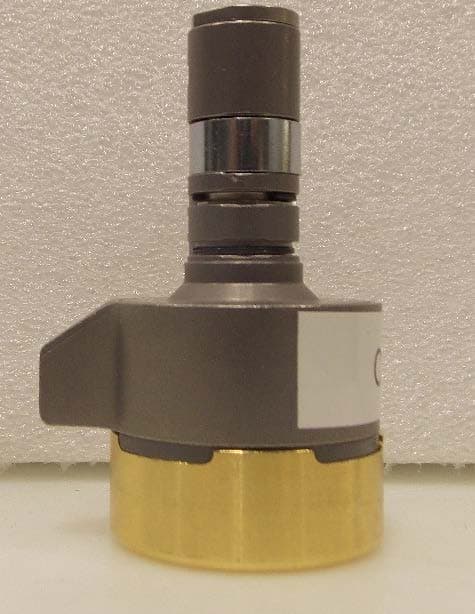
T8H-1SW100
Feb 26, 2020Wireless Lock Switch Core
Equipment Class
DTS - Digital Transmission System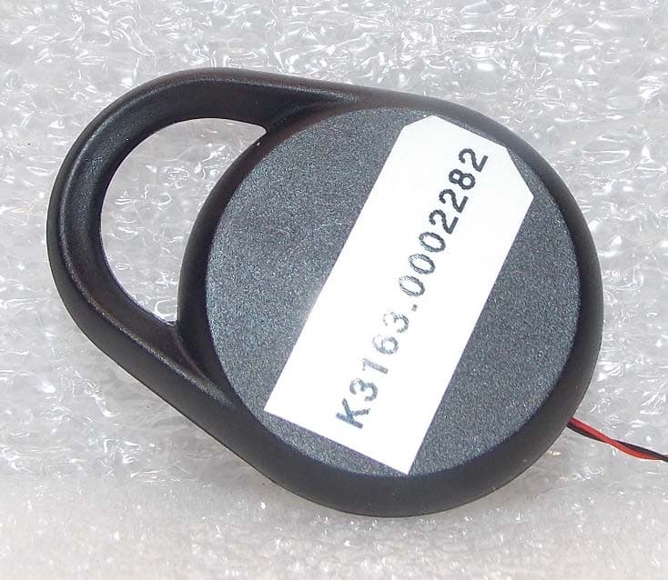
T8H-1SWFOB
Feb 20, 2020Wireless lock FOB
Equipment Class
DTS - Digital Transmission System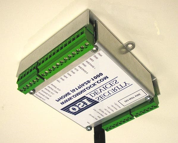
T8H-SDC2K
Mar 06, 2008Single Door Controller
Equipment Class
DTS - Digital Transmission System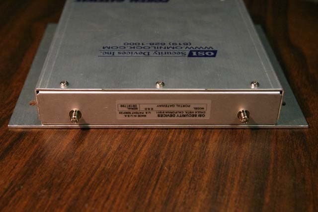
T8H-PG16
Jun 14, 2006Wireless Access Management System Portal Gateway
Equipment Class
DTS - Digital Transmission System