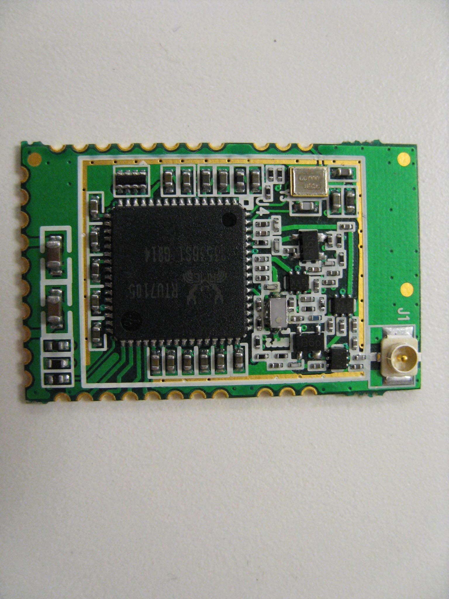
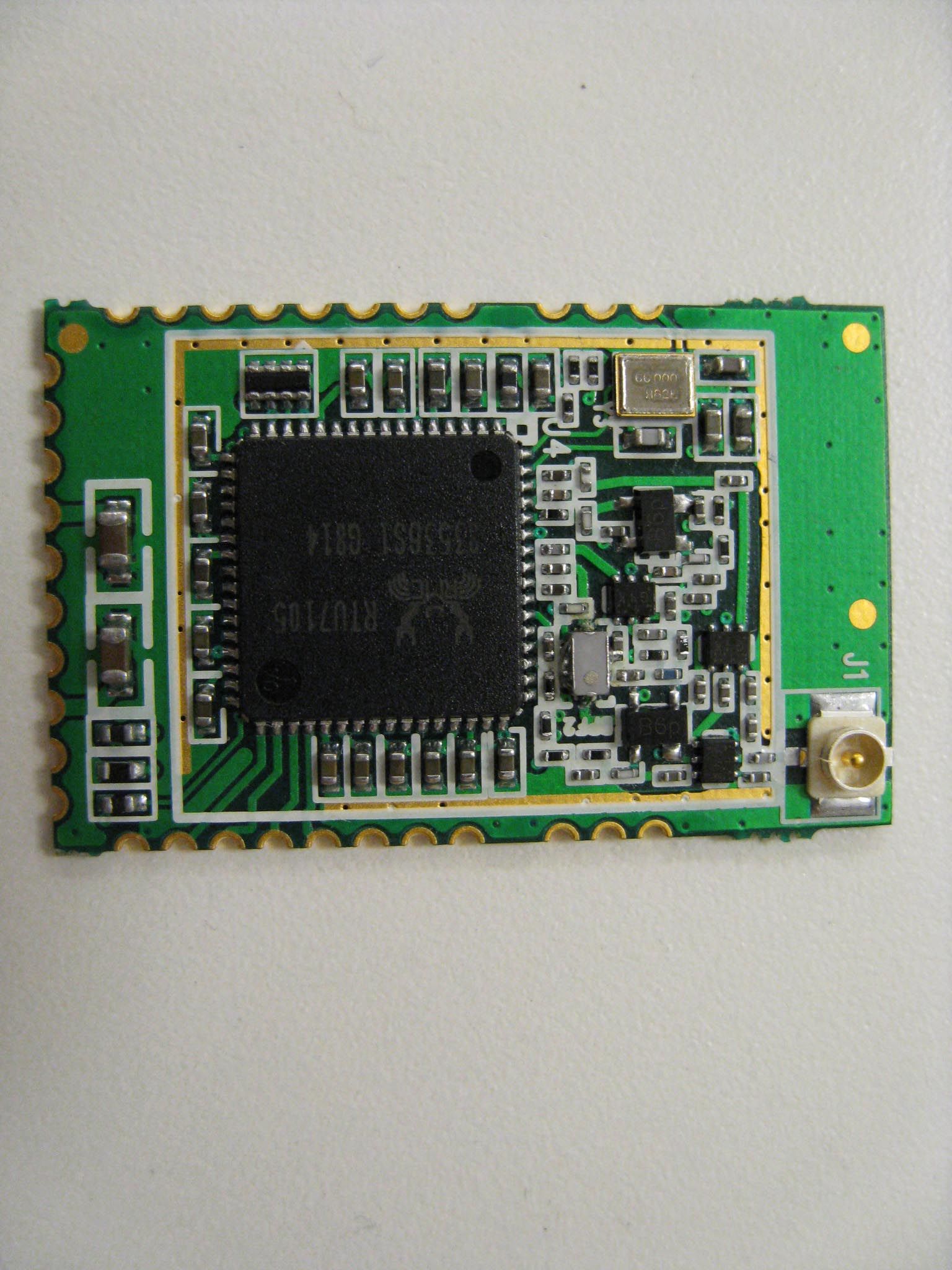
T8YRTU7105-MOD-V3Wireless USB Module
Starix Technology, Inc.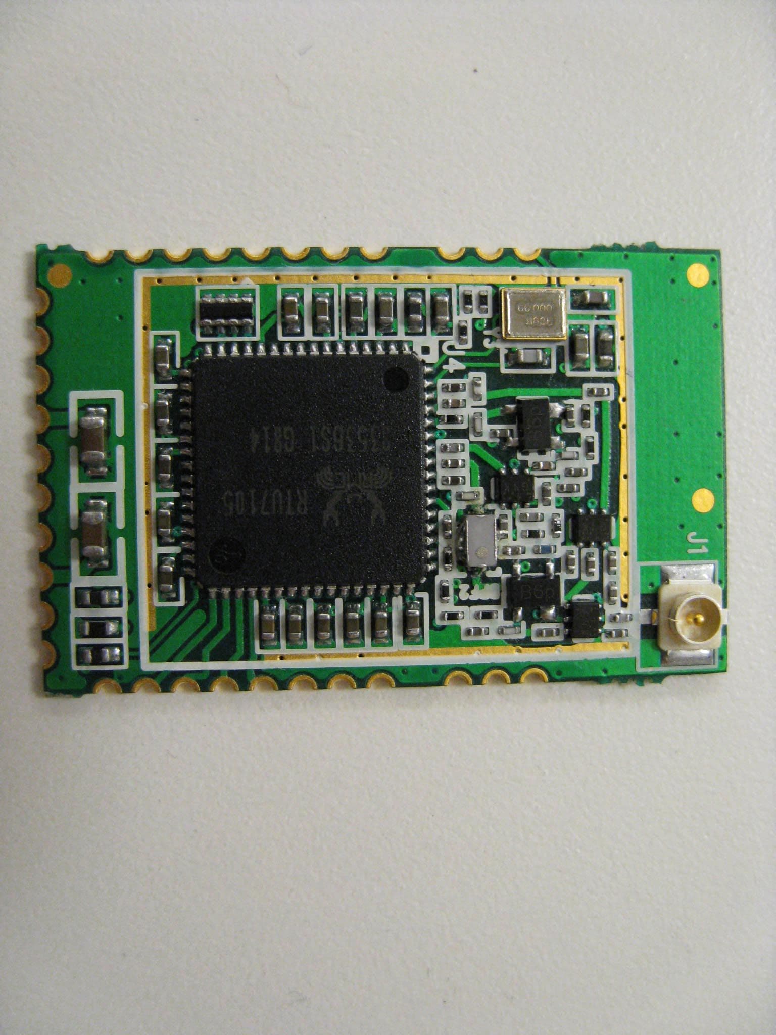
Click to zoom
Application Details
- Equipment Class
- UWB - Ultra Wideband Transmitter
- Date of Grant
- Nov 12, 2008
- Application Purpose
- Original Equipment
- Date of Application
- Jul 13, 2008
- Equipment Note
- Wireless USB Module
- Frequency Range
- 6300.00000000 - 8000.00000000
- Company
- Starix Technology, Inc.
- Country
- United States
Documents & Files
Document Text
Text extracted from the exhibit documents filed with the FCC. Open a document above to read the original.
Users Manual
Wireless USB Module_User’sManual_Rev1.doc Wireless USB Module User’s Manual Rev 1 Hak C. Sok 1 All Rights Reserved by Realtek Semiconductor Corp. Wireless USB Module_User’sManual_Rev1.doc 1 Introduction This document describes the system operation of a Wireless USB Module, as well as driver installation and the use of control software. 2 System Operation 2.1 General Description Wireless USB Module is a UWB module. It can be used in various UWB applications, such as 4- port HWA and WUSB docking station. 2.2 System Block Diagram (with a Carrier Board) The following figure shows the system block diagram of a Wireless USB Module and a carrier board. It accepts +5V from a power adapter or +5V from USB device and converts it to various voltages required by the MAC-PHY chip. Only one crystal is used in the system, which is 66MHz. The system is designed to support both BG1 and BG3 UWB bands as defined in the WiMedia standard. MAC- PHY Chip 66MHz External USB Device USB connector External Power Adapter Power socket BG 1 & 3 Antenna Antenna connector Power Management 2 All Rights Reserved by Realtek Semiconductor Corp. Wireless USB Module_User’sManual_Rev1.doc 2.3 Connector Location Wireless USB Module Carrier Board 3.3 V Regulator Micro Coaxial connector RTU7105 1.8 V Regulator DC Power Jack Not Used Mini-USB Receptacle Type- B 1.2 V Regulator 3 Driver Installation 3.1.Setup the USB connection between the PC and Wireless USB Module. 3.2.Power up Wireless USB Module by inserting the connection between the mini-USB receptacle and the PC. The mini-USB supplies the +5Vdc to the three regulators on the carrier board, which then convert it to various voltages required by the MAC-PHY chip. 3.3.Follow the steps below for the driver installation process. STEP 1. After plugged in the mini-USB connector, Windows will prompt to install driver for the Found New Hardware Wizard. 3 All Rights Reserved by Realtek Semiconductor Corp. Wireless USB Module_User’sManual_Rev1.doc STEP 2. Select, “No, not this time”, then “Next”. STEP 3. Select, “Install from a list or specific location (Advanced)”, then “Next”. 4 All Rights Reserved by Realtek Semiconductor Corp. Wireless USB Module_User’sManual_Rev1.doc STEP 4. Select, “Don’t search, I will choose the driver to install”, then “Next”. STEP 5. Select, “Next”. 5 All Rights Reserved by Realtek Semiconductor Corp. Wireless USB Module_User’sManual_Rev1.doc STEP 6. Select, “Have Disk”. STEP 7. Select “Browse” to search for the driver in a specific folder. STEP 8. Select “TridentFW.inf”, then “Open”. 6 All Rights Reserved by Realtek Semiconductor Corp. Wireless USB Module_User’sManual_Rev1.doc STEP 9. After selecting “TridentFW.inf” it shows the driver name call “RealTek USB Firmware Upgrade Device”, then “Next”. STEP 10. Please ignore all the warning messages generated by Windows and keep installing the driver by selecting the button, “Continue Anyway”. 7 All Rights Reserved by Realtek Semiconductor Corp. Wireless USB Module_User’sManual_Rev1.doc 3.4.Once the previous driver has been installed, Windows will prompt to install another driver for “Generic Cable Association Device for WUSB”. Please cancel the installation of this driver. It is not required for the control software. 4 The Control Software 4.1 Startup procedure of the control software – Wireless USB Module 1. Setup the USB connection between the PC and Wireless USB Module. 2. Power up Wireless USB Module by connecting mini-USB receptacle to PC. 3. Complete the USB driver installation process. 4. Activate Wireless USB Module by double-clicking the “TridentTest.exe” icon. The following window called “RTU7105 Test Utility” should pop up showing the proper execution of Wireless USB Module. 8 All Rights Reserved by Realtek Semiconductor Corp. Wireless USB Module_User’sManual_Rev1.doc 4.2 Control procedure for BG1 or BG3 1. Set “TX PAYLOAD” to 4095. 2. Set “TX IFS” to 10. 3. Select proper options for “TX TFC” (Valid: 1~10) and “TX RATE”. 4. Click “TX/RX Parameters” field’s “Apply” button to activate the above settings. 5. Select “Band Group 1”/ “Band Group 3” option, depending on which BG is being tested, and proper EUT number (according to the marking on the EUT) in the “Band Group” field. 9 6. Click “TX” button once to start the transmission. All Rights Reserved by Realtek Semiconductor Corp.
Block Diagram
Wireless USB Module_System Block Diagram.doc 1.1 System Block Diagram (with a Carrier Board) The following figure shows the system block diagram of a Wireless USB Module and a carrier board. It accepts +5V from a power adapter or +5V from USB device and converts it to various voltages required by the MAC-PHY chip. Only one crystal is used in the system, which is 66MHz. The system is designed to support both BG1 and BG3 UWB bands as defined in the WiMedia standard. MAC- PHY Chip 66MHz External USB Device USB connector External Power Adapter Power socket BG 1 & 3 Antenna Antenna connector Power Management 1 All Rights Reserved by Realtek Semiconductor Corp.
Cover Letter(s)
49 Discovery, Suite 100, Irvine, California 92618, U.S.A. Tel.: 949-296-4195 Fax 949-753-1329 Request for Confidentiality July 10, 2008 Chief, Authorizations Branch Federal Communications Commission 7435 Oakland Mills Road Columbia, MD 21046 Re: Realtek Semiconductor Corp. Certification Application FCC ID: T8YRTU7105-MOD-V3 To Whom It May Concern: Realtek Semiconductor Corp. considers the following materials in its application for certification to be confidential: • Schematics • Bill of Materials These technical items we consider to be proprietary and as such any disclosure would be detrimental to our business and our position in the market place. Sincerely, Jason Li _______________________ RF System Director Confidential and Proprietary Information of Realtek Semiconductor Corp.
Cover Letter(s)
7/10/2008 Chief, Authorizations Branch Federal Communications Commission 7435 Oakland Mills Road Columbia, MD 21046 Modular Approval Request Letter FCC ID: T8YRTU7105-MOD-V3 To Whom It May Concern: Wionics Research, a branch of Realtek Semiconductor Corp. based in Taiwan, would like to have your authorization as a Singular Modular Transmitter of Wireless USB Module, FCC ID T8YRTU7105- MOD-V3. The eight requirements of 47 CFR 15.212 have been met and shown on the following statements. 1. “The modular transmitter must have its own RF shielding”: All shielding necessary for ultra- wideband operation is accomplished by multi-layer construction of printed wire board of Wireless USB Module. 2. “The modular transmitter must have buffered modulation/data inputs”: The Wireless USB Module has buffered data inputs; it is integrated in RTU7105 chip. 3. “The modular transmitter must have its own power supply regulation”: Power regulation function is built in RTU7105 chip, as shown in the block diagram. 4. “The modular transmitter must comply with the antenna requirements of section 15.203 and 15.204(C)”: The Wireless USB Module has a unique micro coaxial coupling between antenna and Wireless USB Module, shown in the following picture and its meets the FCC antenna requirements. Micro coaxial connector Wireless USB Module 5. “The modular transmitter must be tested in a stand-alone configuration ”: The Wireless USB Module was tested in a stand-alone configuration. The detailed test configuration is described in the test report. 6. “The modular transmitter must be equipped with either a permanently affixed label or must be capable of electronically displaying its FCC identification number.”: The EUT Name is marketed with a permanently affixed label shown in label drawing. This label is equipped to the Wireless USB Module at the place shown in the following picture. FCC ID: T8YRTU7105‐MOD‐V3 Product Name: Wireless USB Module Serial Number: 0001 0.74 in. 0.5 in. FCC ID: T8YR T U 7 105 ‐ MO D ‐ V3 Pr od uc t Na me: Wi r e l e ss USB Mo dule Se r i a l Nu m b er : 000 1 Actual size FCC ID: T8YRTU7105‐MOD‐V3 Product Name: Wireless USB Module Serial Number: 0001 7. “The modular transmitter must comply with any specific rule or operating requirements”: The Wireless USB Module was tested as reported in the attached test report. The Wireless USB Module complies with the requirement of 47 CFR part 15 Subsection F. Detailed compliance information is described in the test report. 8. “The modular transmitter must comply with any applicable RF exposure requirements.”: The Wireless USB Module complies with Maximum Permissible Exposure requirement and its calculation is shown in the test report. If you have any questions, please feel free to contact me. Sincerely, __________________________________ Jason Li, 7/10/2008 RF Systems Director Wionics Research Realtek Semiconductor Corp. 49 Discovery #100, Irvine, CA 92618
Cover Letter(s)
49 Discovery, Suite 100, Irvine, California 92618, U.S.A. Tel.: 949-296-4195 Fax 949-753-1329 7/10/08 Federal Communications Commission 7435 Oakland Mills Road Columbia, Maryland 2l046 Gentlemen: This is a letter of authorization to accept TDK RF Solutions as an Agent for Realtek Semiconductor Corp. located at 49 Discovery Suite 100, Irvine, CA 92618, for a period of one year, to sign applications before the Commission on our behalf, to make representations to you on our behalf, and to receive and exchange data between our company and the Commission in connection with certification of the following Realtek Semiconductor product: 4-port HWA and WUSB under FCC Docket Number 20780 and General Docket Number 80-284 pursuant to Part l5 of FCC Rules and Regulations. Please also accept this letter as an attestation that neither Realtek Semiconductor Corp. nor any of its officers, directors, or persons holding 5% or more of the outstanding stock or shares, voting or non-voting, have been denied federal benefits under section 5301 of the Anti-Drug-Abuse act of 1988,21 U.S.C. 853(a). In addition, Realtek Semiconductor Corp. will notify the Federal Communications Commission if, at any time, the situation changes causing Realtek Semiconductor Corp. to be denied federal benefits. If you have any further questions or need additional information, please feel free to give me a call at 949-296-4195. Sincerely, Jason Li ___________________________ RF System Director
ID Label/Location Info
Wireless USB Module FCC Label Placement 6. “The modular transmitter must be equipped with either a permanently affixed label or must be capable of electronically displaying its FCC identification number.”: The EUT Name is marketed with a permanently affixed label shown in label drawing. This label is equipped to the Wireless USB Module at the place shown in the following picture. FCC ID: T8YRTU7105‐MOD‐V3 Product Name: Wireless USB Module Serial Number: 0001 0.74 in. 0.5 in. FCC ID: T8YR T U 7 1 05 ‐ MO D ‐ V3 Pr od uc t Na me: Wi r e l e ss USB Mo dule Se r i a l Nu m b er : 000 1 FCC ID: T8YRTU7105‐MOD‐V3 Product Name: Wireless USB Module Serial Number: 0001 Actual size
Operational Description
Wireless USB Module_TheoryOfOperation.doc Wireless USB Module Theory of Operation Rev 1 1 All Rights Reserved by Realtek Semiconductor Corp. Wireless USB Module_TheoryOfOperation.doc 1 Introduction This document describes how the system operates as a UWB (Ultra-wideband) device. 2 System Operation 2.1 General Description Wireless USB Module is a UWB module. It can be used in various UWB applications, such as 4-port HWA and WUSB docking station. 2.2 Operation A UWB module can operate in both BG1 and BG3. Only one of the band groups will be operating at a given time and this is determined by the MAC-PHY chip. It searches for WiMedia standard-compliant UWB hosts that have associated relationship with it. Once such a host is found, the communication link will be set up and the USB device, e.g. a flash drive attached to the UWB module, can be accessed by the host (computer). 2 All Rights Reserved by Realtek Semiconductor Corp.
Test Report
All services undertaken are subject to the following general policy. Reports are submitted for exclusive use of the client to whom they are addressed. Their significance is subject to the adequacy and representative character of the samples and to the comprehensiveness of the tests, examinations or surveys made. This report shall not be reproduced except in full, without written consent of TDK RF Systems Inc. This report must not be used to claim product endorsement by A2LA, NVLAP nor any other agency of the US Government Compliance report of RTU7105 Module Customer: Realtek Semiconductor Corp. Date: June 23, 2008 TDK Report: TTS-TR-T113-108 Test performed by: TDK R&D Corporation 1101 Cypress Creek Rd Cedar Park, TX 78613 Technician Checked by Radiated 30 MHz to 40 GHz A. Medina K. Yata Report A. Medina K. Yata/P. Carson This document contains confidential information and cannot be disclosed outside of Realtek Semiconductor Corp. or any affiliated company in whole or in part without the express written permission of TDK R&D Corporation. TTS-TR-T113-108 page 2 of 76 1. Executive Summary An EMC evaluation to determine compliance of the RTU7105 Module with requirements of FCC 47 CFR Part 15, Subpart F Section 15.519 was conducted. All references are to the most current version of the Code of Federal Regulations 47 that are currently in effect. In accordance with §2.1033, the following data is presented in support of the Certification of the RTU7105 Module with Chip and Dipole antennas. The client should retain a copy of this document on file for at least 5 years after the manufacturing of the product has been discontinued. Test Description FCC 47 CFR Section Compliance Operational Limitations 15.519(a) The client has been notified of these limitations. In normal operating mode the transmitter will only send data when associated with a receiver. See section 5 for detail. UWB Bandwidth 15.503(d) Yes Radiated Emissions 15.519(c), 15.209 Yes Radiated Emissions in GPS Bands 15.519(d) Yes Peak Emissions within a 50 MHz Bandwidth 15.519(e) Yes Labelling Requirements 15.19/15.212 Yes Report prepared by Approved by Armando Medina Kunio Yata June 23, 2008 June 27, 2008 Page 3 of 76 2. Task Description 2.1. Scope Reference FCC ET Docket No. 98-153, FCC 02-48 First R&O; FCC 47 CFR, Part 15, Subpart A; FCC 47 CFR, Part 15, Subpart B; FCC 47 CFR, Part 15, Subpart C; FCC 47 CFR, Part 15, Subpart F FCC ET Docket No. 04-352, Petition for Waiver of the Part 15 UWB Regulations Filed by MBOA-SIG (Adopted: March 10, 2005) FCC Second R&O 07-56A1 Part 15 unlicensed modular transmitter approval 47 CFR 15.212 Title Revision of Part 15 of the Commission’s Rules Regarding Ultra-Wideband Transmissions Systems; Code of Federal Regulations, Part 15 Subpart A: General Code of Federal Regulations, Part 15 Subpart B: Unintentional Radiators Code of Federal Regulations, Part 15 Subpart C: Intentional Radiators Code of Federal Regulations, Part 15 Subpart F: Ultra-Wideband Operation Purpose of Test To gain FCC Certification for technical requirements for Modular UWB Systems operating between 3.1 GHz and 10.6 GHz. Test Procedures The tests were conducted in accordance with the following documents: FCC ET Docket 98-153, FCC 02-48 First R&O ANSI C63.4: 2003: Methods of Measurement of Radio-Noise Emissions from Low-Voltage Electrical and Electronic Equipment in the Range of 9 kHz to 40 GHz FCC Code of Federal Regulations 47, Part 15 Subpart A: General FCC ET Docket No. 04-352, Petition for Waiver of the Part 15 UWB Regulations Filed by MBOA-SIG (Adopted: March 10, 2005) General Procedures FCC Code of Federal Regulations 47, Part 2 Frequency Allocations and Radio Treaty Matter: General Rules and Regulations Classification of EUT Modular Ultra-Wideband System (Hand-held limit) Page 4 of 76 2.2. Related Submittal(s)/Grant(s) As required in 07-56A1 and 47 CFR 15.212 a cover letter requesting modular approval is included in the application for equipment authorization 2.3. Test Plan Reference Publication Year Title FCC 47 CFR, Part 15, Subpart A 10/2007 Code of Federal Regulations, Part 15 Subpart A: General FCC 47 CFR, Part 15, Subpart B 10/2007 Code of Federal Regulations, Part 15 Subpart B: Unintentional Radiators FCC 47 CFR, Part 15, Subpart C 10/2007 Code of Federal Regulations, Part 15 Subpart C: Intentional Radiators FCC 47 CFR, Part 15, Subpart F 10/2007 Code of Federal Regulations, Part 15 Subpart F: Ultra-Wideband Operation FCC ET Docket 98-153, FCC 02-48 First R&O 04/2002 Revision of Part 15 of the Commission’s Rules Regarding Ultra- Wideband Transmissions Systems: First Report & Order ANSI C63.4 01/2004 Methods of Measurement of Radio- Noise Emissions from Low-Voltage Electrical and Electronic Equipment in the Range of 9 kHz to 40 GHz FCC ET Docket No. 04- 352 3/2005 Petition for Waiver of the Part 15 UWB Regulations Filed by MBOA-SIG FCC 47 CFR, Part 15, Subpart C 04/2007 Part 15.212 unlicensed Modular Transmitter Approval 2.4. Client Information APPLICANT Name: Wionics Research Address: 16269 Laguna Canyon Road, #100, Irvine, CA 92618 Contact Person: Child Sun MANUFACTURER Name: Wionics Research Address: 16269 Laguna Canyon Road, #100, Irvine, CA 92618 Page 5 of 76 Contact Person: Child Sun Page 6 of 76 2.5. Equipment Under Test (EUT) The following information (with the exception of the date information) has been supplied by the applicant. The test results in this report pertain only to the item tested. General Brand Name Realtek Semiconductor Product Name Wireless USB module Model Name or Number RTU7105-Module-V3 Serial Number 0001 Type of Equipment UWB Radio Transmitter Input Power Supply Type DC (3.3V, 1.8V and 1.3V) Classification Modular Ultra-Wideband system (Hand- held limit) Antenna Type Cable length (cm) INPAQ Chip 53.5 ACON Dipole rod 10 Technical Power Supply Requirements 3.3Vdc, 1.8Vdc, 1.3Vdc RF Output Rating -42 dBm EIRP @ 3 meters Operating Frequency Range 3100 MHz to 4800 MHz 6300 MHz to 8000 MHz RF Outpu…
Text truncated - open the document above for the full version.
Contact Information
Applicant
Frederic Battaglia(CEO)
Technical Contact
TDK RF SolutionsArmando Medina
[email protected]512-258-9478
1101 Cypress Creek Rd · Cedar Park, Texas · United States
Non-Technical Contact
TDK RF SolutionsPat Carson
[email protected]209-351-1584
Test Firm
TDK RF Solutions, Inc.Robert Sutton
Technical Specifications
| # | Rule Parts | Frequency Range | Power Output |
|---|---|---|---|
| 2 | 15F | 6.30 GHz - 8.00 GHz | - |
Other Applications from Starix Technology, Inc.
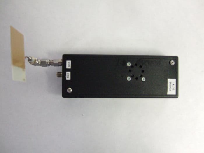
T8YP0029B
Dec 18, 2007One-Port DWA (Device Wire Adapter)
Equipment Class
UWB - Ultra Wideband Transmitter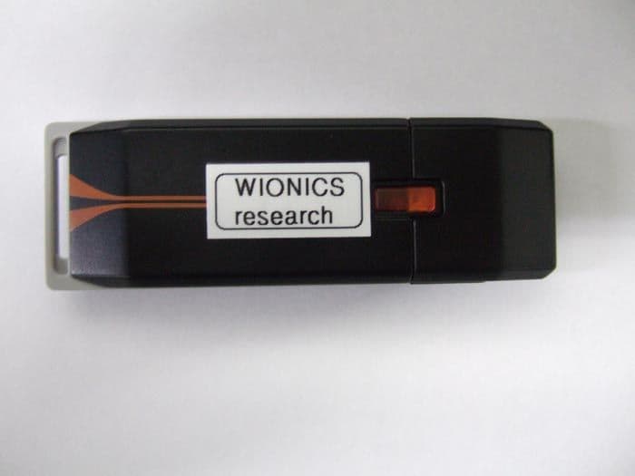
T8YDGLR7CV1
Jul 01, 2007Wireless USB 2.0 Adapter
Equipment Class
UWB - Ultra Wideband Transmitter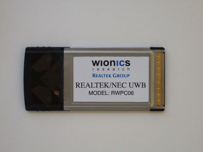
T8YRWPC06
Mar 22, 2007UltraWideband PC Card Adapter
Equipment Class
UWB - Ultra Wideband Transmitter