TA8AKRC163007Radio Unit
Ericsson AB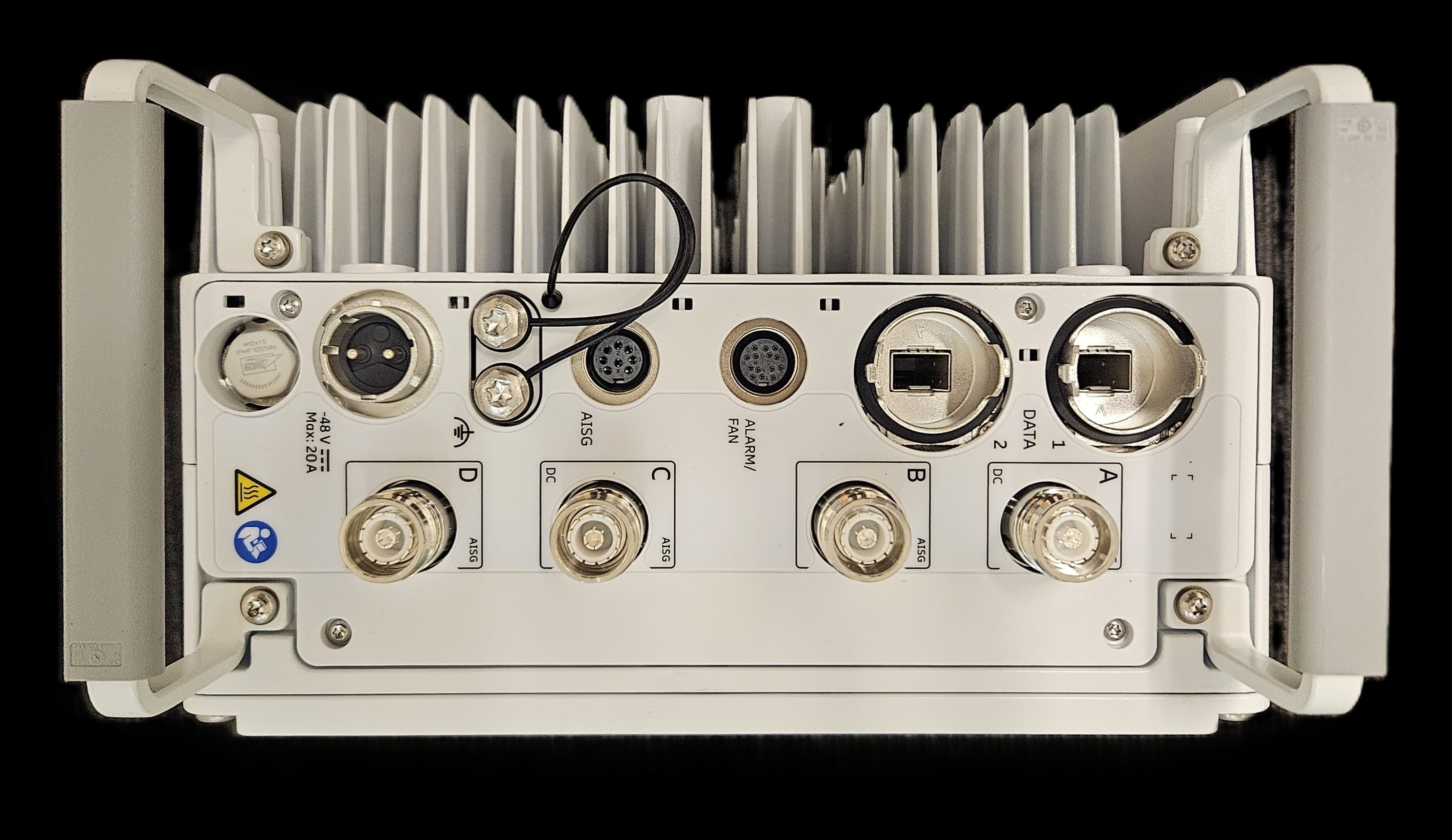
Click to zoom
Application Details
- Equipment Class
- PCB - PCS Licensed Transmitter
- Date of Grant
- Jun 19, 2026
- Application Purpose
- Original Equipment
- Equipment Note
- Radio Unit
- Frequency Range
- 1930.20000000 - 1994.80000000
- Company
- Ericsson AB
- Country
- Sweden
Documents & Files
Document Text
Text extracted from the exhibit documents filed with the FCC. Open a document above to read the original.
RF Exposure Info
www.nemko.com Nemko Canada Inc., a testing laboratory, is accredited by ANSI National Accreditation Board (ANAB). The test results included in this report are within the scope of this accreditation. The ANAB symbol is an official symbol of the ANSI National Accreditation Board, used under licence. FCC and ISED RSS-102– MPE Calculation; Date: January 2026 RF Exposure Compliance – MPE Calculation Report C h o o s e S c a n d i n a v i a n t r u s t Applicant company: Ericsson AB Model number (HVIN): AS163007 Model name (PMN): Radio 4438 44B2/B25 44B66 C FCC Identification: FCC ID: TA8AKRC163007 ISED certification number: IC: 287AB-AS163007 Product type: Fixed Device Device category 1 Consumer Device for General Population/Uncontrolled Exposure Device category 2 Professional Device for Occupational/Controlled Exposure Date of issue: June 18, 2026 Compliance Specifications: FCC 47 CFR Part 1 Subpart I, §§1.1307, 1.1310 FCC 47 CFR Part 2 Subpart J, §§2.1091, 2.1093 FCC KDB 447498 D01 General RF Exposure Guidance v06 FCC KDB 865664 D01 RF Exposure Procedures and Equipment Authorization Policies ISED Canada RSS-102 Issue 6 December 15, 2023 MPE calculation report Product info: FCC ID: TA8AKRC163007 IC: 287AB-AS163007 Model: Radio 4438 44B2/B25 44B66 C Page 2 of 8 Test locations of Nemko Canada Inc. Ottawa site Montréal site GTA Cambridge site Facility address 303 River Road Ottawa, Ontario Canada K1V 1H2 Tel: +1 613 737 9680 Fax: +1 613 737 9691 292 Labrosse Avenue Pointe-Claire, Québec Canada H9R 5L8 Tel: +1 514 694 2684 Fax: +1 514 694 3528 1-130 Saltsman Drive Cambridge, Ontario Canada N3E 0B2 Tel: +1 519 650 4811 Test site identifier - FCC CA2040 CA2041 CA0101 Test site identifier – ISED Canada 2040A-4 2040G-5 24676 ANAB File Number AT-3195 AT-3193 AT-3194 Andrey Adelberg Senior EMC/Wireless Specialist Prepared by Signature Limits of responsibility The results presented in this report apply solely to the specific device model tested and are valid only for the operating conditions and installation requirements specified herein. Testing was conducted in accordance with ISO/IEC 17025:2017 requirements, and all results fall within the scope of Nemko Canada's accreditation. This MPE evaluation is based on the maximum power levels and operating conditions specified. Any modifications to the device hardware, software, or installation that could affect RF output power or antenna characteristics may invalidate this compliance demonstration. Copyright notification This report may be reproduced by the applicant in its entirety for regulatory submission and internal use. Any use of this report by third parties, including reliance on its contents or decisions made based on it, is solely at the risk of those third parties. Nemko Canada Inc. assumes no responsibility for any damages incurred by third parties as a result of actions taken based on this report. © Nemko Canada Inc. All rights reserved. MPE calculation report Product info: FCC ID: TA8AKRC163007 IC: 287AB-AS163007 Model: Radio 4438 44B2/B25 44B66 C Page 3 of 8 1. Executive Summary This report presents the Maximum Permissible Exposure (MPE) analysis to demonstrate compliance with FCC and ISED RF exposure requirements. The evaluation considers both single transmitter operation and simultaneous multi-transmitter scenarios where applicable. 2. Key Findings Compliance status Complies Critical separation distances FCC Uncontrolled: 18 m, FCC Controlled: 7.8 m ISED Uncontrolled: 26.2 m, ISED Controlled: 10.4 m Special conditions or limitations N/A MPE calculation report Product info: FCC ID: TA8AKRC163007 IC: 287AB-AS163007 Model: Radio 4438 44B2/B25 44B66 C Page 4 of 8 MPE calculations for simultaneous transmission Device Classification Requirements Portable Device Definition (§2.1093) Devices designed for use by a person where the radiating structure is within 20 cm of the user's body require SAR evaluation rather than MPE calculation. Mobile Device Definition Devices installed in vehicles or with permanently installed antennas may use MPE calculations if minimum separation distances can be established. Fixed/Base Station Definition Stationary transmitters with controlled access to antenna locations may use MPE calculations for both occupational and general population exposure scenarios. 3. References, definitions and limits for FCC FCC §2.1091(d) (2) For operations within the frequency range of 300 kHz and 6 GHz (inclusive), the limits for maximum permissible exposure (MPE), derived from whole-body SAR limits and listed in Table 1 in paragraph (e)(1) of this section, may be used instead of whole-body SAR limits as set forth in paragraphs (a) through (c) of this section to evaluate the environmental impact of human exposure to RF radiation as specified in §1.1307(b) of this part, except for portable devices as defined in §2.1093 of this chapter as these evaluations shall be performed according to the SAR provisions in §2.1093. Table 1: §1.1310(e)(1)—Power Density Limits for Maximum Permissible Exposure (MPE) Frequency range (MHz) Power density (mW/cm 2 ) Averaging time (minutes) (i) Limits for Occupational/Controlled Exposure 0.3–3.0 *(100) ≤6 3.0–30 *(900 / f 2 ) <6 30–300 1.0 <6 300–1500 f / 300 <6 1500–100000 5 <6 (ii) Limits for General Population/Uncontrolled Exposure 0.3–1.34 *(100) <30 1.34–30 *(180 / f 2 ) <30 30–300 0.2 <30 300–1500 f / 1500 <30 1500–100000 1.0 <30 Notes: f = frequency in MHz. * = Plane-wave equivalent power density. MPE calculation report Product info: FCC ID: TA8AKRC163007 IC: 287AB-AS163007 Model: Radio 4438 44B2/B25 44B66 C Page 5 of 8 4. References, definitions and limits for ISED RSS-102 Section 5.3.2 The power density reference levels, and associated reference period for devices employed by the general public (uncontrolled environment) and controlled-use devices (controlled environment) are specified in table below. Note that the power density limits specified in this table apply to whole body exposure conditions. Ta…
Text truncated - open the document above for the full version.
Test Setup Photos
Section 3: Equipment under test (EUT) details Report ID: REP163346 Page 12 of 218 3.5 Setup photographs Figure 3.5-1: Set up photo for Radio Compliance Testing Figure 3.5-2: Set up photo for Radio Compliance Testing (Frequency Stability) Section 3: Equipment under test (EUT) details Report ID: REP163346 Page 13 of 218 Setup photographs, continued Figure 3.5-3: EUT Set-up photo for Radiated Emissions [30 MHz to 1000 MHz] Figure 3.5-4: EUT Set-up photo for Radiated Emission above 1 GHz Section 3: Equipment under test (EUT) details Report ID: REP163346 Page 14 of 218 Setup photographs, continued Figure 3.5-5: EUT Set-up photo for Radiated Emissions [18-40 GHz]
Test Report
CapacityCompactCoverage ericsson.com/antenna-system Antenna 2200 0L 2M 1.3m KRE 101 2452/1 65° | 2x 1695–2690 MHz | 18.0 dBi Electrical downtilt set by integrated RET Y1Y2 LeftRight 2Ericsson Antenna System | KRE 101 2452/1 – Antenna 2200 0L 2M 1.3mAugust 2021 Left side, midbandY1, connector 1–2 Frequency RangeMHz1695 – 18801850 – 19901920 – 21702300 – 24002490 – 2690 Gain at mid TiltdBi17.417.617.817.817.9 Gain over all TiltsdBi17.4 ± 0.517.6 ± 0.517.7 ± 0.617.8 ± 0.817.8 ± 0.8 Horizontal Pattern: Azimuth Beamwidth°67 ± 2.565 ± 1.365 ± 1.164 ± 2.661 ± 3.2 Front-to-Back Ratio, Total Power, ± 30° dB> 25> 25> 25> 25> 25 Cross Polar Discrimination at Boresight dB> 30> 29> 29> 24> 22 Cross Polar Discrimination over Sector dB> 18.0> 17.5> 14.5> 8.0> 5.5 Azimuth Beam Port-to-Port Tracking dB< 1.5< 1.5< 1.5< 2.0< 3.0 Vertical Pattern: Elevation Beamwidth°7.5 ± 0.57.0 ± 0.26.7 ± 0.55.9 ± 0.25.4 ± 0.3 Electrical Downtilt continuously adjustable °0.0 – 10.0 Tilt Accuracy°< 0.5< 0.5< 0.6< 0.5< 0.6 First Upper Sidelobe Suppression dB> 15> 16> 17> 18>15 Upper Sidelobe Suppression, 20° Sector above Main Beam dB> 14> 15> 16> 16> 14 Intra-Cluster IsolationdB≥ 28 Port to Port IsolationdB≥ 28 (Y1 // Y2) Max. Effective Power per Port W200 Values based on NGMN-P-BASTA (version 11.1) requirements. Right side, midbandY2, connector 3–4 Frequency RangeMHz1695 – 18801850 – 19901920 – 21702300 – 24002490 – 2690 Gain at mid TiltdBi17.317.517.717.717.9 Gain over all TiltsdBi17.3 ± 0.717.5 ± 0.717.7 ± 0.717.6 ± 0.917.8 ± 0.9 Horizontal Pattern: Azimuth Beamwidth°67 ± 2.564 ± 1.564 ± 1.162 ± 2.960 ± 3.1 Front-to-Back Ratio, Total Power, ± 30° dB> 24> 24> 23> 23> 24 Cross Polar Discrimination at Boresight dB> 33> 30> 30> 22> 22 Cross Polar Discrimination over Sector dB> 16.0> 15.5> 14.0> 8.5> 6.5 Azimuth Beam Port-to-Port Tracking dB< 1.5< 1.5< 2.0< 2.0< 3.5 Vertical Pattern: Elevation Beamwidth°7.5 ± 0.57.0 ± 0.36.7 ± 0.45.8 ± 0.25.3 ± 0.3 Electrical Downtilt continuously adjustable °0.0 – 10.0 Tilt Accuracy°< 0.4< 0.4< 0.3< 0.3< 0.3 First Upper Sidelobe Suppression dB> 17> 16> 18> 17>16 Upper Sidelobe Suppression, 20° Sector above Main Beam dB> 15> 15> 17> 15> 15 Intra-Cluster IsolationdB≥ 28 Port to Port IsolationdB≥ 28 (Y2 // Y1) Max. Effective Power per Port W200 Values based on NGMN-P-BASTA (version 11.1) requirements. 3Ericsson Antenna System | KRE 101 2452/1 – Antenna 2200 0L 2M 1.3mAugust 2021 1081 | 42.61260 | 49.6 1293.7 | 50.9 Material:Reflector screen and dipoles: Aluminum. Fiberglass housing: It covers totally the internal antenna components. The special design reduces the sealing areas to a minimum and guarantees the best weather protection. Fiberglass material guarantees optimum performance with regards to stability, stiffness, UV resistance and painting. The color of the radome is light grey. All nuts and bolts: Stainless steel or hot-dip galvanized steel. Grounding:The metal parts of the antenna including the mounting kit and the inner conductors are DC grounded. Electrical specifications, all ports ImpedanceΩ50 VSWR< 1.5 Return LossdB> 14 Inter-Cluster IsolationdB> 28 Passive IntermodulationdBc< −153 (2 x 43 dBm carrier) Polarization°+45, −45 Max. Effective Power for the Antenna W600 Values based on NGMN-P-BASTA (version 11.1) requirements. Mechanical specifications Input4x 4.3-10 female Connector Position bottom Adjustment MechanismIntegrated RET, continuously adjustable Wind load (at Rated Wind Speed: 150 km/h) N | lbfFrontal: 345 | 78 Maximal: 345 | 78 Max. Wind Velocitykm/h mph 200 124 Height / Width / Depthmm inches 1260 / 265 / 120 49.6 / 10.4 / 4.7 Weightkg lb 10.8 / 13.6 (clamps incl.) 23.8 / 30 (clamps incl.) Packing Size mm inches 1535 / 315 / 185 60.4 / 12.4 / 7.3 Scope of SupplyAntenna, mounting kit (50–115 mm) incl. mech. Tilt-kit (0°–16°) SXA 120 131/1, integr. RET KRY 121 78/1 Correlation Table Frequency rangeArrayConnector / Ports 1695–2690 MHzY11–2 1695–2690 MHzY23–4 Layout of interface Y1Y2 LeftRight 141.7 | 5.6 129.4 | 5.1 265 | 10.4 185 | 7.3 65 | 2.5 94.3 | 37.1 88.3 | 34.7 Bottom view * Dimensiones refer to radome All dimensions in mm | inches Ericsson enables communications service providers to capture the full value of connectivity. The company’s portfolio spans Networks, Digital Services, Mana- ged Services, and Emerging Business and is designed to help our customers go digital, increase efficiency and find new revenue streams. Ericsson’s investments in innovation have delivered the benefits of telephony and mobile broadband to billions of people around the world. The Ericsson stock is listed on Nasdaq Stockholm and on Nasdaq New York. Read more on www.ericsson.com The content of this document is subject to revision without notice due to continued progress in methodology, design and manufacturing. Ericsson shall have no lia- bility for any error or damage of any kind resulting from the use of this document ericsson.com KRE 101 2452/1 Rev. B © Ericsson AB 2021
Test Report
Section 8 Testing data Test name Occupied bandwidth (Band 66) Specification FCC Part 2, RSS-Gen, Issue 5 Report ID: REP163346 Page 212 of 218 Test data, continued Figure 8.13-9: Sample plot for NR 25 MHz channel Figure 8.13-10: Sample plot for NR 30 MHz channel Figure 8.13-11: Sample plot for NR 35 MHz channel Figure 8.13-12: Sample plot for NR 40 MHz channel Figure 8.13-13: Sample plot for SA 0.4 MHz channel Section 8 Testing data Test name Occupied bandwidth (Band 2/25) Specification FCC Part 2, RSS-Gen, Issue 5 Report ID: REP163346 Page 213 of 218 8.14 Occupied bandwidth (Band 2/25) 8.14.1 Definitions and limits FCC §2.1049: The emission bandwidth is defined as the width of the signal between two points, one below the carrier center frequency and one above the carrier center frequency, outside of which all emissions are attenuated at least 26 dB below the transmitter power. RSS-Gen, 6.7 The occupied bandwidth or the “99% emission bandwidth” is defined as the frequency range between two points, one above and the other below the carrier frequency, within which 99% of the total transmitted power of the fundamental transmitted emission is contained. The occupied bandwidth shall be reported for all equipment in addition to the specified bandwidth required in the applicable RSSs. 8.14.2 Test summary Test date May 05,2026 – May 08, 2026 Test engineer Sagarkumar Patel 8.14.3 Observations, settings and special notes Testing was performed per ANSI C63.26 Paragraphs 5.4.3 and 5.4.4 methods. All modulation configurations were pretested to identify the representative modulation yielding the worst-case power level. The modulations that resulted in the worst-case scenarios were MODtm1p1 or QPSK. Spectrum analyzer settings: Detector mode Peak Resolution bandwidth ≥1 % of EBW Video bandwidth RBW × 3 Trace mode Max Hold Section 8 Testing data Test name Occupied bandwidth (Band 2/25) Specification FCC Part 2, RSS-Gen, Issue 5 Report ID: REP163346 Page 214 of 218 8.14.4 Test data Table 8.14-1: Occupied bandwidth results for LTE 5 MHz channel Remarks Frequency, MHz 26 dB BW, MHz 99% OBW, MHz 5 MHz, Low channel 1932.5 4.747 4.490 5 MHz, Mid channel 1962.5 4.780 4.484 5 MHz, Top channel 1992.5 4.755 4.485 Table 8.14-2: Occupied bandwidth results for LTE 10 MHz channel Remarks Frequency, MHz 26 dB BW, MHz 99% OBW, MHz 10 MHz, Low channel 1935.0 9.524 8.944 10 MHz, Mid channel 1962.5 9.538 8.943 10 MHz, Top channel 1990.0 9.583 8.967 Table 8.14-3: Occupied bandwidth results for LTE 15 MHz channel Remarks Frequency, MHz 26 dB BW, MHz 99% OBW, MHz 15 MHz, Low channel 1937.5 14.270 13.455 15 MHz, Mid channel 1962.5 14.390 13.401 15 MHz, Top channel 1987.5 14.320 13.487 Table 8.14-4: Occupied bandwidth results for LTE 20 MHz channel Remarks Frequency, MHz 26 dB BW, MHz 99% OBW, MHz 20 MHz, Low channel 1940.0 19.100 17.911 20 MHz, Mid channel 1962.5 19.330 17.930 20 MHz, Top channel 1985.0 19.190 17.893 Table 8.14-5: Occupied bandwidth results for NR 5 MHz channel Remarks Frequency, MHz 26 dB BW, MHz 99% OBW, MHz 5 MHz, Low channel 1932.5 4.050 4.495 5 MHz, Mid channel 1962.5 4.786 4.499 5 MHz, Top channel 1992.5 4.833 4.492 Table 8.14-6: Occupied bandwidth results for NR 10 MHz channel Remarks Frequency, MHz 26 dB BW, MHz 99% OBW, MHz 10 MHz, Low channel 1935.0 9.764 9.243 10 MHz, Mid channel 1962.5 9.759 9.256 10 MHz, Top channel 1990.0 9.269 9.736 Table 8.14-7: Occupied bandwidth results for NR 15 MHz channel Remarks Frequency, MHz 26 dB BW, MHz 99% OBW, MHz 15 MHz, Low channel 1937.5 14.960 14.158 15 MHz, Mid channel 1962.5 14.930 14.180 15 MHz, Top channel 1987.5 14.950 14.166 Table 8.14-8: Occupied bandwidth results for NR 20 MHz channel Remarks Frequency, MHz 26 dB BW, MHz 99% OBW, MHz 20 MHz, Low channel 1940.0 19.990 19.044 20 MHz, Mid channel 1962.5 20.020 19.076 20 MHz, Top channel 1985.0 19.970 19.087 Section 8 Testing data Test name Occupied bandwidth (Band 2/25) Specification FCC Part 2, RSS-Gen, Issue 5 Report ID: REP163346 Page 215 of 218 Test data, continued Table 8.14-9: Occupied bandwidth results for NR 25 MHz channel Remarks Frequency, MHz 26 dB BW, MHz 99% OBW, MHz 25 MHz, Low channel 1942.5 24.970 23.794 25 MHz, Mid channel 1962.5 25.030 23.828 25 MHz, Top channel 1982.5 24.970 23.848 Table 8.14-10: Occupied bandwidth results for NR 30 MHz channel Remarks Frequency, MHz 26 dB BW, MHz 99% OBW, MHz 30 MHz, Low channel 1945.0 29.990 28.427 30 MHz, Mid channel 1962.5 29.860 28.460 30 MHz, Top channel 1980.0 29.890 28.360 Table 8.14-11: Occupied bandwidth results for NR 35 MHz channel Remarks Frequency, MHz 26 dB BW, MHz 99% OBW, MHz 30 MHz, Low channel 1947.5 35.270 33.657 30 MHz, Mid channel 1962.5 35.330 33.560 30 MHz, Top channel 1977.5 35.290 33.598 Table 8.14-12: Occupied bandwidth results for NR 40 MHz channel Remarks Frequency, MHz 26 dB BW, MHz 99% OBW, MHz 40 MHz, Low channel 1950.0 40.420 38.720 40 MHz, Mid channel 1962.5 40.410 38.726 40 MHz, Top channel 1975.0 40.410 38.697 Table 8.14-13: Occupied bandwidth results for SA 0.4 MHz channel Remarks Frequency, MHz 26 dB BW, kHz 99% OBW, kHz 0.4 MHz, Low channel 1930.2 316.2 210.49 0.4 MHz, Mid channel 1962.5 317.9 212.75 0.4 MHz, Top channel 1994.8 319.2 211.11 Figure 8.14-1: Sample plot for LTE 5 MHz channel Figure 8.14-2: Sample plot for LTE 10 MHz channel Section 8 Testing data Test name Occupied bandwidth (Band 2/25) Specification FCC Part 2, RSS-Gen, Issue 5 Report ID: REP163346 Page 216 of 218 Test data, continued Figure 8.14-3: Sample plot for LTE 15 MHz channel Figure 8.14-4: Sample plot for LTE 20 MHz channel Figure 8.14-5: Sample plot for NR 5 MHz channel Figure 8.14-6: Sample plot for NR 10 MHz channel Figure 8.14-7: Sample plot for NR 15 MHz channel Figure 8.14-8: Sample plot for NR 20 MHz channel Section 8 Testing data Test name Occupied bandwidth (Band 2/25) Specification FCC Part 2, RSS-Gen, Issue 5 Report ID: REP163346 Page 217 of 218 Test data, continued Figure 8.14-9: Sample plot for NR 25 MHz channel Figure 8.14-10: Sam…
Text truncated - open the document above for the full version.
Test Report
Section 8 Testing data Test name Spurious emissions at RF antenna connector (Band 66 & 2/25) Specification FCC Part 27 and RSS-139 Issue 4 and FCC Part 24 and RSS-133 Issue 7 Report ID: REP163346 Page 178 of 218 Test data, continued Figure 8.8-13: Conducted spurious LTE 5 MHz+ NR 5 MHz (Band 2/25) and LTE 5 + NR 5 MHz (Band 66) channel bandwidth l, Dual Band operation Figure 8.8-14: Conducted spurious NR 5 MHz+ SA (Band 2/25) and LTE 5 + NR 5 MHz (Band 66) channel bandwidth, Dual Band operation Figure 8.8-15: Conducted spurious emissions of NR 5 MHz+ LTE 5 MHz + LTE 5 MHz (Band 2/25) and NR 5 MHz + LTE 5 MHz + SA (Band 66) MHz channel bandwidth, Dual Band operation Section 8 Testing data Test name Band edge measurement at RF antenna connector (Band 66 & 2/25) Specification FCC Part 27 and RSS-139 Issue 4 and FCC Part 24 and RSS-133 Issue 7 Report ID: REP163346 Page 179 of 218 8.9 Band edge measurement at RF antenna connector (Band 66 & Band 2/25) 8.9.1 Definitions and limits FCC §27.53: (h) AWS emission limits (1) General protection levels. Except as otherwise specified below, for operations in the 1695–1710 MHz, 1710–1755 MHz, 1755–1780 MHz, 1915–1920 MHz, 1995–2000 MHz, 2000–2020 MHz, 2110–2155 MHz, 2155–2180 MHz, and 2180–2200 bands, the power of any emission outside a licensee's frequency block shall be attenuated below the transmitter power (P) in watts by at least 43 + 10 log 10 (P) dB. (3) Measurement procedure. (i) Compliance with this provision is based on the use of measurement instrumentation employing a resolution bandwidth of 1 megahertz or greater. However, in the 1-megahertz bands immediately outside and adjacent to the licensee's frequency block, a resolution bandwidth of at least one percent of the emission bandwidth of the fundamental emission of the transmitter may be employed. The emission bandwidth is defined as the width of the signal between two points, one below the carrier center frequency and one above the carrier center frequency, outside of which all emissions are attenuated at least 26 dB below the transmitter power. (ii) When measuring the emission limits, the nominal carrier frequency shall be adjusted as close to the licensee's frequency block edges, both upper and lower, as the design permits. (iii) The measurements of emission power can be expressed in peak or average values, provided they are expressed in the same parameters as the transmitter power. FCC §24.238(a): Out of band emissions. The power of any emission outside of the authorized operating frequency ranges must be attenuated below the transmitting power (P) by a factor of at least 43 + 10 log(P) dB. (b) Measurement procedure. Compliance with these rules is based on the use of measurement instrumentation employing a resolution bandwidth of 1 MHz or greater. However, in the 1 MHz bands immediately outside and adjacent to the frequency block a resolution bandwidth of at least one percent of the emission bandwidth of the fundamental emission of the transmitter may be employed. A narrower resolution bandwidth is permitted in all cases to improve measurement accuracy provided the measured power is integrated over the full required measurement bandwidth (i.e. 1 MHz or 1 percent of emission bandwidth, as specified). The emission bandwidth is defined as the width of the signal between two points, one below the carrier center frequency and one above the carrier center frequency, outside of which all emissions are attenuated at least 26 dB below the transmitter power. RSS-139, Section 5.6: For the unwanted emission limits, in the 1 MHz bands immediately outside and adjacent to the frequency block group, the power shall be measured with a resolution bandwidth of at least 1% of the occupied bandwidth (OBW). Beyond these 1 MHz bands, a resolution bandwidth of 1 MHz shall be used. A narrower resolution bandwidth may be used, provided that the measured power is integrated over the full required measurement bandwidth of 1 MHz, or 1% of the OBW, as applicable. Unwanted emissions shall be measured in terms of average values. For all equipment, the TRP or total conducted power (sum of conducted power across all antenna connectors) of the unwanted emissions outside the frequency block or frequency block group shall not exceed the limits shown in table below: Table 8.9-1: Unwanted emissions limits Offset from the edge of the frequency block or frequency group Unwanted emission limits 1 MHz -13 dBm/(1% of OB*) > 1 MHz -13 dBm/MHz Notes: *OB is the occupied bandwidth 8.9.2 Test summary Test date May 05,2026 – May 08, 2026 Test engineer Sagarkumar Patel Section 8 Testing data Test name Band edge measurement at RF antenna connector (Band 66 & 2/25) Specification FCC Part 27 and RSS-139 Issue 4 and FCC Part 24 and RSS-133 Issue 7 Report ID: REP163346 Page 180 of 218 8.9.3 Observations, settings and special notes − All measurements were performed using an average (RMS) detector per ANSI C63.26 Paragraph 5.7.2 method. − Limit line (43 + 10 log 10 (P) or −13 dBm) was adjusted for MIMO operation by 6 dB* or 3 dB*: −13 dBm – 6 dB = −19 dBm, −13 dBm – 3 dB = −16 dBm *MIMO correction factor for LTE and NR: 10 × Log 10 (4) = 6 dB *MIMO correction factor for NB-IoT SA: 10 × Log 10 (2) = 3 dB − RBW 1 MHz, VBW was wider than RBW. − − All modulation configurations were pretested to identify the representative modulation yielding the worst-case power level. The modulations that resulted in the worst-case scenarios were 16-QAM. − The measurements were performed using the calibrated path. Section 8 Testing data Test name Band edge measurement at RF antenna connector (Band 66 & 2/25) Specification FCC Part 27 and RSS-139 Issue 4 and FCC Part 24 and RSS-133 Issue 7 Report ID: REP163346 Page 181 of 218 8.9.4 Test data On the plots below the measured Channel Power value in the “Total Channel Power” column must be −19 dBm and lower. Figure 8.9-1: Conducted emission at the lower band edge Figure 8.9-2: Conducted emission 1 MHz away at the l…
Text truncated - open the document above for the full version.
Test Report
Section 8 Testing data Test name Band edge measurement at RF antenna connector (Band 2/25) Specification FCC Part 24 and RSS-133, Issue 7 Report ID: REP163346 Page 153 of 218 Test data, continued On the plots below the measured Channel Power value in the “Total Channel Power” column must be −19 dBm and lower. Figure 8.7-74: Conducted emission at the lower band edge Figure 8.7-75: Conducted emission at the upper frequency block edge of the low channel Frequency: 1930 MHz Mode: Single-carrier operation Frequency: 1995 MHz Mode: Single-carrier operation Meas. BW: 1 MHz Tech.: NR 25 MHz Meas. BW: 1 MHz Tech.: NR 25 MHz Limit: −19 dBm/1 MHz Notes: None Limit: −19 dBm/MHz Notes: None Figure 8.7-76 : Conducted emission at the upper band edge Figure 8.7-77: Conducted emission at the lower frequency block edge of the top channel Frequency: 1995 MHz Mode: Single-carrier operation Frequency: 1970 MHz Mode: Single-carrier operation Meas. BW: 1 MHz Tech.: NR 25 MHz Meas. BW: 1 MHz Tech.: NR 25 MHz Limit: −19 dBm/1 MHz Notes: None Limit: −19 dBm/1 MHz Notes: None Section 8 Testing data Test name Band edge measurement at RF antenna connector (Band 2/25) Specification FCC Part 24 and RSS-133, Issue 7 Report ID: REP163346 Page 154 of 218 Test data, continued On the plots below the measured Channel Power value in the “Total Channel Power” column must be −19 dBm and lower. Figure 8.7-78: Conducted emission at the lower band edge Figure 8.7-79: Conducted emission at the upper frequency block edge of the low channel Frequency: 1930 MHz Mode: Single-carrier operation Frequency: 1960 MHz Mode: Single-carrier operation Meas. BW: 1 MHz Tech.: NR 30 MHz Meas. BW: 1 MHz Tech.: NR 30 MHz Limit: −19 dBm/1 MHz Notes: None Limit: −19 dBm/MHz Notes: None Figure 8.7-80 : Conducted emission at the upper band edge Figure 8.7-81: Conducted emission at the lower frequency block edge of the top channel Frequency: 1995 MHz Mode: Single-carrier operation Frequency: 1965 MHz Mode: Single-carrier operation Meas. BW: 1 MHz Tech.: NR 30 MHz Meas. BW: 1 MHz Tech.: NR 30 MHz Limit: −19 dBm/1 MHz Notes: None Limit: −19 dBm/1 MHz Notes: None Section 8 Testing data Test name Band edge measurement at RF antenna connector (Band 2/25) Specification FCC Part 24 and RSS-133, Issue 7 Report ID: REP163346 Page 155 of 218 Test data, continued On the plots below the measured Channel Power value in the “Total Channel Power” column must be −19 dBm and lower. Figure 8.7-82: Conducted emission at the lower band edge Figure 8.7-83: Conducted emission at the upper frequency block edge of the low channel Frequency: 1930 MHz Mode: Single-carrier operation Frequency: 1965 MHz Mode: Single-carrier operation Meas. BW: 1 MHz Tech.: NR 35 MHz Meas. BW: 1 MHz Tech.: NR 35 MHz Limit: −19 dBm/1 MHz Notes: None Limit: −19 dBm/MHz Notes: None Figure 8.7-84 : Conducted emission at the upper band edge Figure 8.7-85: Conducted emission at the lower frequency block edge of the top channel Frequency: 1995 MHz Mode: Single-carrier operation Frequency: 1960 MHz Mode: Single-carrier operation Meas. BW: 1 MHz Tech.: NR 35 MHz Meas. BW: 1 MHz Tech.: NR 35 MHz Limit: −19 dBm/1 MHz Notes: None Limit: −19 dBm/1 MHz Notes: None Section 8 Testing data Test name Band edge measurement at RF antenna connector (Band 2/25) Specification FCC Part 24 and RSS-133, Issue 7 Report ID: REP163346 Page 156 of 218 Test data, continued On the plots below the measured Channel Power value in the “Total Channel Power” column must be −19 dBm and lower. Figure 8.7-86: Conducted emission at the lower band edge Figure 8.7-87: Conducted emission at the upper frequency block edge of the low channel Frequency: 1930 MHz Mode: Single-carrier operation Frequency: 1970 MHz Mode: Single-carrier operation Meas. BW: 1 MHz Tech.: NR 40 MHz Meas. BW: 1 MHz Tech.: NR 40 MHz Limit: −19 dBm/1 MHz Notes: None Limit: −19 dBm/MHz Notes: None Figure 8.7-88 : Conducted emission at the upper band edge Figure 8.7-89: Conducted emission at the lower frequency block edge of the top channel Frequency: 1995 MHz Mode: Single-carrier operation Frequency: 1955 MHz Mode: Single-carrier operation Meas. BW: 1 MHz Tech.: NR 40 MHz Meas. BW: 1 MHz Tech.: NR 40 MHz Limit: −19 dBm/1 MHz Notes: None Limit: −19 dBm/1 MHz Notes: None Section 8 Testing data Test name Band edge measurement at RF antenna connector (Band 2/25) Specification FCC Part 24 and RSS-133, Issue 7 Report ID: REP163346 Page 157 of 218 Test data, continued On the plots below the measured Channel Power value in the “Total Channel Power” column must be −19 dBm and lower. Figure 8.7-90: Conducted emission at the lower band edge Figure 8.7-91: Conducted emission 1 MHz away at the lower band edge Frequency: 1930 MHz Mode: Multi-carrier operation Frequency: 1929 MHz Mode: Multi-carrier operation Meas. BW: 1% of EBW Tech.: 3xNR 5 MHz Meas. BW: 1 MHz Tech.: 3xNR 5 MHz Limit: −19 dBm/50 kHz Notes: None Limit: −19 dBm/MHz Notes: None Figure 8.7-92: Conducted emission at the upper frequency block edge of the lower channel Figure 8.7-93: Conducted emission 1 MHz away at the upper frequency block edge of the lower channel Frequency: 1945 MHz Mode: Multi-carrier operation Meas. BW: 1% of EBW Tech.: 3xNR 5 MHz Limit: −19 dBm/50 kHz Notes: None Frequency: 1946 MHz Mode: Multi-carrier operation Meas. BW: 1 MHz Tech.: 3xNR 5 MHz Limit: −19 dBm/MHz Notes: None Section 8 Testing data Test name Band edge measurement at RF antenna connector (Band 2/25) Specification FCC Part 24 and RSS-133, Issue 7 Report ID: REP163346 Page 158 of 218 Test data, continued On the plots below the measured Channel Power value in the “Total Channel Power” column must be −19 dBm and lower. Figure 8.7-94: Conducted emission at the upper band edge Figure 8.7-95: Conducted emission 1 MHz away at the upper band edge Frequency: 1995 MHz Mode: Multi-carrier operation Frequency: 1996 MHz Mode: Multi-carrier operation Meas. BW: 1% of EBW Tech.: 3xNR 5 MHz Meas. BW: 1 MHz Tech.: 3xNR 5 MHz Limit: −19 dBm/150 kHz Notes:…
Text truncated - open the document above for the full version.
Test Report
Section 8 Testing data Test name Spurious emissions at RF antenna connector (Band 25) Specification FCC Part 27, and RSS-133 Issue 7 Report ID: REP163346 Page 130 of 218 Test data, continued Figure 8.6-49: Conducted spurious emissions of 3xNR 20 MHz mid channel, three -carrier contiguous operation Figure 8.6-50: Conducted spurious emissions of 3xNR 20 MHz top channel, …
Text truncated - open the document above for the full version.
Contact Information
Applicant
Qiwei Wang(Head of PEU Radio Atlantic)
[email protected]Fax: +46 10 716 00 28
Technical Contact
Ericsson IncRanjeet Bhattacharya
6300 Legacy Drive · Plano, Texas, 75024 · United States
Test Firm
Nemko Canada Inc. (Ottawa)Charles Neal
[email protected]Fax: 613-737-9691
Technical Specifications
| # | Rule Parts | Frequency Range | Power Output | Emission | Tolerance |
|---|---|---|---|---|---|
| 1 | 24E | 1.93 GHz - 1.99 GHz | 21.38 W | 5M00W7D | 1.74Hz |
| 2 | 24E | 1.94 GHz - 1.99 GHz | 41.5 W | 15M0W7D | 1.74Hz |
| 3 | 24E | 1.94 GHz - 1.99 GHz | 41.4 W | 20M0W7D | 1.74Hz |
| 4 | 24E | 1.94 GHz - 1.99 GHz | 41.8 W | 10M0W7D | 1.74Hz |
| 5 | 24E | 1.94 GHz - 1.98 GHz | 41.5 W | 25M0W7D | 1.74Hz |
| 6 | 24E | 1.95 GHz - 1.98 GHz | 41.5 W | 30M0W7D | 1.74Hz |
| 7 | 24E | 1.95 GHz - 1.98 GHz | 40.6 W | 35M0W7D | 1.74Hz |
| 8 | 24E | 1.95 GHz - 1.98 GHz | 41.2 W | 40M0W7D | 1.74Hz |
| 9 | 24E | 1.93 GHz - 1.99 GHz | 21.23 W | 400KW7D | 1.74Hz |
| 1 | 27 | 2.11 GHz - 2.20 GHz | 21.63 W | 5M00W7D | 2.37Hz |
| 11 | 27 | 2.12 GHz - 2.19 GHz | 42.46 W | 10M0W7D | 2.37Hz |
| 12 | 27 | 2.12 GHz - 2.19 GHz | 42.46 W | 15M0W7D | 2.37Hz |
| 13 | 27 | 2.12 GHz - 2.19 GHz | 42.66 W | 20M0W7D | 2.37Hz |
| 14 | 27 | 2.12 GHz - 2.19 GHz | 42.56 W | 25M0W7D | 2.37Hz |
| 15 | 27 | 2.13 GHz - 2.19 GHz | 42.46 W | 30M0W7D | 2.37Hz |
| 16 | 27 | 2.13 GHz - 2.18 GHz | 42.07 W | 35M0W7D | 2.37Hz |
| 17 | 27 | 2.13 GHz - 2.18 GHz | 42.46 W | 40M0W7D | 2.37Hz |
| 18 | 27 | 2.11 GHz - 2.20 GHz | 21.62 W | 400KW7D | 2.37Hz |
Other Applications from Ericsson AB

TA8BKRY901523
Jul 23, 2026Radio Unit
Equipment Class
PCB - PCS Licensed Transmitter
TA8BKRY901515
Jul 23, 2026Radio Unit
Equipment Class
TNB - Licensed Non-Broadcast Station Transmitter
TA8BKRY901551
Jul 06, 2026Radio Unit
Equipment Class
TNB - Licensed Non-Broadcast Station Transmitter
TA8AKRD901316
Jun 29, 2026Multi-standard remote radio
Equipment Class
PCB - PCS Licensed Transmitter
TA8AKRD901303
Jun 17, 2026Antenna Integrated Radio Unit
Equipment Class
TNB - Licensed Non-Broadcast Station Transmitter