TDA-FA1Adapter for Wireless headset for two-way radios
Radeum, Inc. (DBA FreeLinc)
Click to zoom
Application Details
- Equipment Class
- DXT - Part 15 Low Power Transceiver, Rx Verified
- Date of Grant
- Oct 13, 2005
- Application Purpose
- Original Equipment
- Date of Application
- Oct 13, 2005
- Equipment Note
- Adapter for Wireless headset for two-way radios
- Frequency Range
- 13.56000000 - 13.95900000
- Company
- Radeum, Inc. (DBA FreeLinc)
- Country
- United States
Documents & Files
Document Text
Text extracted from the exhibit documents filed with the FCC. Open a document above to read the original.
Users Manual
FCC Compliance This equipment has been tested and found to comply with the limits for a class B digital device, pursuant to Part 15 of the FCC rules. These limits are designed to provide reasonable protection against harmful interference in a residential installation. This equipment generates, uses and can radi - ate radio frequency energy and, if not installed and used in accordance with the manufacturer’s instructions, may cause interference harmful to radio communications. There is no guarantee however, that interference will not occur in a particular installation. If this equipment does cause harmful interference to radio or television reception, which can be determined by comparing the equipment off and on, the user is encouraged to try to correct the interference by one or more of the following measures: • Reorient or relocate the receiving antenna. • Increase the separation between the equipment and receiver. • Connect the equipment into an outlet on a circuit different from that to which the receiver is connected. • Consult your supplier or an experienced radio/TV technician for assistance. Warning: Changes or modifications to this unit not expressly approved by the party responsible for compliance could void the user’s authority to operate this equipment. Safety Information Caution: To reduce the risk of fire or injury to persons, read and follow these instruc- tions. Do not dispose of headset in a fire. The cells may explode. Check with local codes for possible battery disposal instructions. Use only the supplied charging unit to charge the headset from an AC voltage or wall outlet. If the headset becomes hot during charging, disconnect the AC adapter from the wall and contact qualified support personnel. Do not disassemble the AC adapter of this product as it may expose you to danger - ous voltages or other risks. Incorrect reassembly can cause electric shock when the product is subsequently used. Do not use the charger outdoors or in damp areas. Only charge the headset battery in accordance with the instructions of this manual. Never submerge your headset in water or other liquids. Protect your headset from spills, excessive rain, and wet locations. Do not use liquid cleaners or aerosol cleaners as they may damage the headset or fin- ish of the headset. Use a dry cloth to clean the external portions of the headset. Do not stick anything inside the product as this may damage internal components. This product conforms to the following safety standards: ANSI/UL 60950-1 1st Ed. CAN/CSA C22.2 No. 60950-1-03 EN 60950-1 1st Ed. SAFETY AND WARRANTY INFORMATION Warranty FCC Compliance Safety Information TABLE OF CONTENTS INTRODUCTION AND GENERAL INFORMATION CONTENTS IN PACKAGES PARTS OF THE PRODUCT Diagram/Terms Indicator Lights GENERAL OPERATION Using Your Headset for the First Time Step One: Attach Adapter Step Two: Turn On Adapter TIPS AND SUGGESTIONS TROUBLESHOOTING Table of Contents Introduction and General Information Congratulations, and thank you for choosing FreeLinc products to enhance your two-way radio communications. Each FreeLinc adapter is compatible with other FreeLinc commu- nications accessories that use cutting-edge LibertyLink™ wire- less technology from Aura Communications, Inc. Based on near- field magnetic induction communication (NFMC), LibertyLink supports mobility, freedom-of-motion, exceptional battery life, audio integrity, ease-of-use, durability, secure communications and comfort. LibertyLink is the first technology of its kind to be implemented into practical voice and audio solutions. FreeLinc communications accessories operate in a “bubble” that envelops one to three meters of each user’s personal space, and is – by the laws of physics – fully private and secure. The result is an easier to use, lower cost system that makes far more efficient use of power and bandwidth than conventional RF systems. By limiting the range and bandwidth to only what the applica- tion requires, the product achieves a very substantial savings in power. Signals are designed to propagate only within a two- meter range, enabling a huge power and battery advantage (up to six times) over standard RF technology. Thank you for choosing FreeLinc. Anthony J. Sutera President & CEO Contents in Package: FreeLinc Adapter: One Adapter One User Guide Parts of the Product - Adapter Diagram/Terms Here are the components of your FreeMotion 200 adapter. ��� �� LED Indicator On/Off Toggle Switch Push-to-Talk Button Locking Screw Locking Hole Radio Mounting Clip Adapter Indicator Lights The indicator light on your FreeMotion 200 adapter indicates wireless communication status as follows: General Operation Using Your Headset for the First Time Step One: Attach Adapter Fit adapter to the accessory interface of the portable radio (see your portable radio’s user manual if you need assistance locating the accessory interface). If your adapter has a mounting clip on top, this will fit into a corresponding notch on top of your portable radio. If your adapter does not have a mounting clip, use the set screw (see diagram) to secure it to your radio. When properly attached, the spring-loaded pins should align with the contacts on the accessory interface of your portable radio and adapter should fit securely. Step Two: Turn On Adapter Turn on your portable radio and set toggle switch to “On” position. (see diagram) Note that this will auto - LED BEHAVIORINDICATION Red, Flashing 2x per secondSeek mode Green, SolidMate found, pairing/linking in progress Green, Flashing 2x per secondLink active Orange, Flashing 2x per secondVOX mode active LED not illuminated Sleep mode matically silence the speaker on your portable radio and route all communications to the headset. For information on how to operate this product in conjunction with a FreeLinc communications accessory, please refer to the user manual that came with the acces - sory. Tips and Suggestions To learn more about Magnetic Induction Technology, pleas…
Text truncated - open the document above for the full version.
Users Manual
From: John Lair [[email protected]] Sent: Tuesday, October 11, 2005 6:11 PM To: Roland Gubisch ES-Box; Terre Wolak ES-Atl Cc: 'Tony Sutera '; 'Doug Dobyns' Subject: RE: TCB Review of FreeLinc FCC ID: TDA-FA1 and TDA-FMT200 Roland & Terre, Attached please find the artwork for the sticker that we will adhere to the bottom left corner of the outside front cover of the current user manual. Please let me know if this solves the problem. Thank you, John Lair -----Original Message----- From: Roland Gubisch ES-Box [mailto:[email protected]] Sent: Monday, October 10, 2005 8:59 AM To: John Lair; Terre Wolak ES-Atl Subject: RE: TCB Review of FreeLinc FCC ID: TDA-FA1 and TDA-FMT200 John, 15.19(a)(5) allows devices which are too small for the full text to be included on the device label, to place the required text either in the user manual or on the device package. A sticker could be used either for adding the text in the manual, or onto the package. The rule is not specific as to the outside of the packaging or inside of the lid, so either location would be acceptable. In any case you will need to specify which location will be used, either by description or illustration. Regards, Roland
Cover Letter(s)
1(1) Attention: Application Examiner Reviewing Engineer Re: Request for confidentiality Applicant: Radeum, Inc. FCC ID: TDA-FA1 under project number 3079725 To whom it may concern, Request is hereby submitted by Radeum, Inc. (DBA FreeLinc) to withhold permanently from public review certain portions of the application for equipment certification for the referenced FCC identifiers. This request for confidentiality is made pursuant to 47 CFR 0.457(d) and 0.459 of the FCC Rules. In particular, the following sections of the application are to be kept permanently confidential: • Schematics • Detailed Block diagrams • Detailed Operational/Functional Description Rationale for request for confidentiality: Radeum, Inc. has invested considerable time and materials in research and development to produce the referenced product. Disclosure of the permanently confidential portions of this application to competitors would not only give them significant competitive advantages in developing similar products, but would also disclose successful implementation of unpublished, leading edge technology developed by us. The fee for confidentiality has been submitted along with the fee for certification. If you have questions or need further information, please contact the undersigned. Sincerely, John Lair President Radeum, Inc. (DBA FreeLinc)
Cover Letter(s)
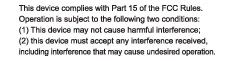
-----Original Message----- From: John Lair [mailto:[email protected]] Sent: Wednesday, October 12, 2005 11:48 AM To: Roland Gubisch ES-Box; Terre Wolak ES-Atl Cc: 'Tony Sutera '; 'Doug Dobyns' Subject: RE: TCB Review of FreeLinc FCC ID: TDA-FA1 and TDA-FMT200 Roland, Attached are forms 731; please let me know right away if you can or cannot open them. Also attached are revised confidentiality requests. Please let me know right away if they are acceptable. If there are any other issues, please let me know right away. Thank you, John -----Original Message----- From: Roland Gubisch ES-Box [mailto:[email protected]] Sent: Wednesday, October 12, 2005 8:34 AM To: John Lair; Terre Wolak ES-Atl Cc: Tony Sutera ; Doug Dobyns Subject: RE: TCB Review of FreeLinc FCC ID: TDA-FA1 and TDA-FMT200 John, Here are the remaining issues to be addressed: A. I cannot open the updated Form 731 you submitted in PDF format. Please re-send. Without being able to read the Form 731, I can't tell if you answered the prior open question: ****************************** ADMINISTRATIVE (2) The frequency range of operation is not specified in the Form 731 for either device. The frequency should be entered either as the center of the band for single-band operation, or the centers of the highest and lowest bands for multi-band operation. ***************************** B. The updated Confidentiality request asks for the internal photos to be held confidential. This is not normally allowed, on the basis that anyone can purchase the product and look at the inside. You should consider deleting this item from the Confidentiality request, or provide additional justification in the letter, such as: the device is potted, and would be damaged or destroyed by user entry. Regards, Roland -----Original Message----- From: John Lair [mailto:[email protected]] Sent: Wednesday, October 12, 2005 10:14 AM To: Roland Gubisch ES-Box; Terre Wolak ES-Atl Cc: 'Tony Sutera '; 'Doug Dobyns' Subject: RE: TCB Review of FreeLinc FCC ID: TDA-FA1 and TDA-FMT200 Roland, Excellent. Am I correct then to assume that we are all set to receive our FCC Grant of Authorization? If not, please let me know what to expect from here. Thanks, John -----Original Message----- From: Roland Gubisch ES-Box [mailto:[email protected]] Sent: Wednesday, October 12, 2005 7:48 AM To: John Lair; Terre Wolak ES-Atl Cc: Tony Sutera ; Doug Dobyns Subject: RE: TCB Review of FreeLinc FCC ID: TDA-FA1 and TDA-FMT200 John, The label, with your description of its location, is acceptable for meeting the labeling requirements of FCC Part 15. Regards, Roland -----Original Message----- From: John Lair [mailto:[email protected]] Sent: Tuesday, October 11, 2005 6:11 PM To: Roland Gubisch ES-Box; Terre Wolak ES-Atl Cc: 'Tony Sutera '; 'Doug Dobyns' Subject: RE: TCB Review of FreeLinc FCC ID: TDA-FA1 and TDA-FMT200 Roland & Terre, Attached please find the artwork for the sticker that we will adhere to the bottom left corner of the outside front cover of the current user manual. Please let me know if this solves the problem. Thank you, John Lair -----Original Message----- From: Roland Gubisch ES-Box [mailto:[email protected]] Sent: Monday, October 10, 2005 8:59 AM To: John Lair; Terre Wolak ES-Atl Subject: RE: TCB Review of FreeLinc FCC ID: TDA-FA1 and TDA-FMT200 John, 15.19(a)(5) allows devices which are too small for the full text to be included on the device label, to place the required text either in the user manual or on the device package. A sticker could be used either for adding the text in the manual, or onto the package. The rule is not specific as to the outside of the packaging or inside of the lid, so either location would be acceptable. In any case you will need to specify which location will be used, either by description or illustration. Regards, Roland -----Original Message----- From: John Lair [mailto:[email protected]] Sent: Saturday, October 08, 2005 3:59 PM To: Roland Gubisch ES-Box; Terre Wolak ES-Atl Subject: RE: TCB Review of FreeLinc FCC ID: TDA-FA1 and TDA-FMT200 Roland, What about a sticker? If that's acceptable, would it need to go on the outside of the packaging, or on the inside of the package lid? Thanks, John -----Original Message----- From: Roland Gubisch ES-Box [mailto:[email protected]] Sent: Saturday, October 08, 2005 1:54 PM To: Terre Wolak ES-Atl; John Lair Subject: RE: TCB Review of FreeLinc FCC ID: TDA-FA1 and TDA-FMT200 Terre, A user manual insert is acceptable. We will need a copy of the insert or its text. Roland -----Original Message----- From: John Lair [mailto:[email protected]] Sent: Tuesday, October 04, 2005 3:00 PM To: Terre Wolak ES-Atl Subject: RE: TCB Review of FreeLinc FCC ID: TDA-FA1 and TDA-FMT200 We've already printed mass quantities of these manuals. Is it acceptable to include an insert? Thanks, John -----Original Message----- From: Terre Wolak ES-Atl [mailto:[email protected]] Sent: Tuesday, October 04, 2005 12:52 PM To: John Lair Cc: Roland Gubisch ES-Box; Nicholas Abbondante ES-Box Subject: RE: TCB Review of FreeLinc FCC ID: TDA-FA1 and TDA-FMT200 John, Thank you for the 731 forms and confidentiality request letters received today. On another note, Roland's final review of the FCC labels and User manuals indicate that neither of them carries the label text required in 15.19(a)(3): "This device complies with part 15 of the FCC Rules. Operation is subject to the following two conditions: (1) This device may not cause harmful interference, and (2) this device must accept any interference received, including interference that may cause undesired operation." When the device is smaller than the palm of a normal hand (as it is in these cases), it is permissible to delete the text from the FCC ID label and place it in the User manual. Similar text is now present in the User manuals, but it is not identical to the text above. Please resolve this issue as soon as possible. Regards, Terre -----Or…
Text truncated - open the document above for the full version.
External Photos
Request for new FCC Certification for FCC ID: TDA-FA1 under project number 3079725 Exhibit 7b: Housing Photographs: Section 1: Housing interior Section 2: Housing Interior with Electronics Section 3: Exterior, Assembled
ID Label/Location Info
Request for new FCC Certification for FCC ID: TDA-FA1 under project number 3079725 Exhibit 7c: FCC ID Label Photographs:
Internal Photos
Request for new FCC Certification for FCC ID: TDA-FA1 under project number 3079725 Exhibit 7a: Interior Photographs: Section 1: Assembled electronic boards Section 2: Individual Electronic Boards
Test Report
EMI Report for Radeum on Model: Freelinc Wireless Headset System Report Number 3079725.EMI Page 2 of 21 1.0 Job Description 1.1 Client Information This EUT has been tested at the request of Company: Radeum 2144 S. Highland Drive Suite #160 Salt Lake City, UT, 84106 Contact: John Lair Telephone: Fax: 801-467-1199 801-467-6099 1.2 Equipment Under Test Equipment Type: Wireless Headset System Model Number(s): Freelinc Wireless Headset System Serial number(s): BOX0507271156-(001, 003, 005, 007) (ITS assigned) -001 and –005 are Headsets, –003 and –007 are Relays Manufacturer: Radeum EUT receive date: 07/27/2005 EUT received condition: Good Test start date: 07/28/2005 Test end date: 08/12/2005 1.3 Test Plan Reference: Tested according to the standards listed and ANSI C63.4-2003. 1.4 Test Configuration 1.4.1 Block Diagram The EUT set must be in the proximity of another EUT set in order to trigger transmission at 13.956 MHz in addition to the normal 13.56 MHz transmission. The Headset and Relay must be ~1.1 meters apart maximum, and the two systems must be ~0.5 meters apart. Headset Turntable Headset Relay Relay EMI Report for Radeum on Model: Freelinc Wireless Headset System Report Number 3079725.EMI Page 3 of 21 1.4.2 Cable List: Cable Shielding Connector Length (m) Qty. None 1.4.3 Support Equipment: Name: Model No.: Serial No.: None 1.5 Mode of Operation: The EUT was activated from a fresh, charged battery in transmit mode. The EUT software disables transmission while in charge mode, so this mode was not tested to the transmitter requirements. EMI Report for Radeum on Model: Freelinc Wireless Headset System Report Number 3079725.EMI Page 4 of 21 2.0 Test Summary TEST STANDARD RESULTS FCC Part 15 Subpart C 15.225 SUB-TEST TEST PARAMETER COMMENT FCC Parts 15.205, 15.209, 15.215, 15.225 RF Output Power and Radiated and Restricted Band Emissions Emissions below specified limits Pass FCC Part 15.207 Line-Conducted Emissions Emissions below specified limits Pass FCC Parts 15.225 Frequency Stability Frequency drift must not exceed ±0.01% Pass FCC Parts 15.205 Occupied Bandwidth and Restricted Bands The 20dB bandwidth must not extend into or drift into the restricted bands Pass EMI Report for Radeum on Model: Freelinc Wireless Headset Sysem Report Number 3079725.EMI Page 5 of 21 3.0 Sample Calculations The field strength is calculated by adding the Antenna Factor and Cable Factor, and subtracting the Amplifier Gain (if any) from the measured reading. The basic equation with a sample calculation is as follows: FS = RA + AF + CF - AG Where FS = Field Strength in dBμV/m RA = Receiver Amplitude (including preamplifier) in dBμV CF = Cable Attenuation Factor in dB AF = Antenna Factor in dB AG = Amplifier Gain in dB In the following table(s), the reading shown on the data table reflects the preamplifier gain. An example for the calculations in the following table is as follows. Assume a receiver reading of 52.0 dBμV is obtained. The antenna factor of 7.4 dB and cable factor of 1.6 dB is added. The amplifier gain of 29 dB is subtracted, giving a field strength of 32 dBμV/m. This value in dBμV/m was converted to its corresponding level in μV/m. RA = 52.0 dBμV AF = 7.4 dB/m CF = 1.6 dB AG = 29.0 dB FS = 32 dBμV/m Level in μV/m = [10( 32 dBμV/m)/20] = 39.8 μV/m The following is how net line-conducted readings were determined: NF = RF + LF + CF + AF Where NF = Net Reading in dBμV RF = Reading from receiver in dBμV LF = LISN Correction Factor in dB CF = Cable Correction Factor in dB AF = Attenuator Loss Factor in dB To convert from dBμV to μV or mV the following was used: UF = 10 (NF / 20) where UF = Net Reading in μV Example: NF = RF + LF + CF + AF = 28.5 + 0.2 + 0.4 + 20.0 = 49.1 dBμV UF = 10 (48.1 dBμV / 20) = 254 μV/m EMI Report for Radeum on Model: Freelinc Wireless Headset System Report Number 3079725.EMI Page 6 of 21 3.1 Measurement Uncertainty Compliance of the product is based on the measured value. However, the measurement uncertainty is included for informational purposes. The expanded uncertainty (k = 2) for radiated emissions from 30 to 1000 MHz has been determined to be: ±3.5 dB at 10m, ±3.8 dB at 3m The expanded uncertainty (k = 2) for mains conducted emissions from 150 kHz to 30 MHz has been determined to be: ±2.6 dB The expanded uncertainty (k = 2) for telecom port conducted emissions from 150 kHz to 30 MHz has been determined to be: ±3.2 for ISN and voltage probe measurements ±3.1 for current probe measurements EMI Report for Radeum on Model: Freelinc Wireless Headset Sysem Report Number 3079725.EMI Page 7 of 21 3.2 Site Description Test Site(s): 2, Field Behind Site 2 Our OATS are 3m and 10m sheltered emissions measurement ranges located in a light commercial environment in Boxborough, Massachusetts. They meet the technical requirements of ANSI C63.4-2003 and CISPR 22:1993/EN 55022:1994 for radiated and conducted emission measurements. The shelter structure is entirely fiberglass and plastic, with outside dimensions of 33 ft x 57 ft. The structure resembles a quonset hut with a center ceiling height of 16.5 ft. The testing floor is covered by a galvanized sheet metal groundplane that is earth-grounded via copper rods around the perimeter of the site. The joints between individual metal sheets are bridged with a 2 inch wide metal strips to provide low RF impedance contact throughout. The sheets are screwed in place with stainless steel, round-head screws every three inches. Site illumination and HVAC are provided from beneath the ground reference plane through flush entry ports, the port covers are electrically bonded to the ground plane. A flush metal turntable with 12 ft. diameter and 5000 lb. load capacity (12,000 lb. in Site 3) is provided for floor-standing equipment. A wooden table 80 cm high is used for table-top equipment. The turntable is electrically connected to the ground plane with three copper straps. The straps are connected to the turntable at the center of it with ground braid. T…
Text truncated - open the document above for the full version.
Test Setup Photos
Setup Photos
Contact Information
Applicant
Douglas H. Dobyns(President)
Technical Contact
FreeLincDoug Dobyns
[email protected]801 467 1199
2144 South Highland Drive · Salt Lake City, Utah · United States
Non-Technical Contact
FreeLincTony Sutera
[email protected]801 467 1199
Test Firm
Intertek Testing Services NA Inc.Roland Gubisch
Technical Specifications
| # | Rule Parts | Frequency Range | Power Output |
|---|---|---|---|
| 1 | 15C | 13.56 MHz - 13.959 MHz | - |
Other Applications from Radeum, Inc. (DBA FreeLinc)

TDA-FPTT
May 16, 2011Wireless PTT
Equipment Class
DXX - Part 15 Low Power Communication Device Transmitter
TDA-FA02
Apr 01, 2007Adapter for wireless devices for two-way Radios
Equipment Class
DXT - Part 15 Low Power Transceiver, Rx Verified
TDA-FMC200
Apr 27, 2006Wireless speaker-microphone for two-way radios
Equipment Class
DXT - Part 15 Low Power Transceiver, Rx Verified
TDA-FMT200
Oct 13, 2005Wireless headset for two-way radios
Equipment Class
DXT - Part 15 Low Power Transceiver, Rx Verified