TE6-DM2200ARemote Transceiver Module
Murata Electronics North America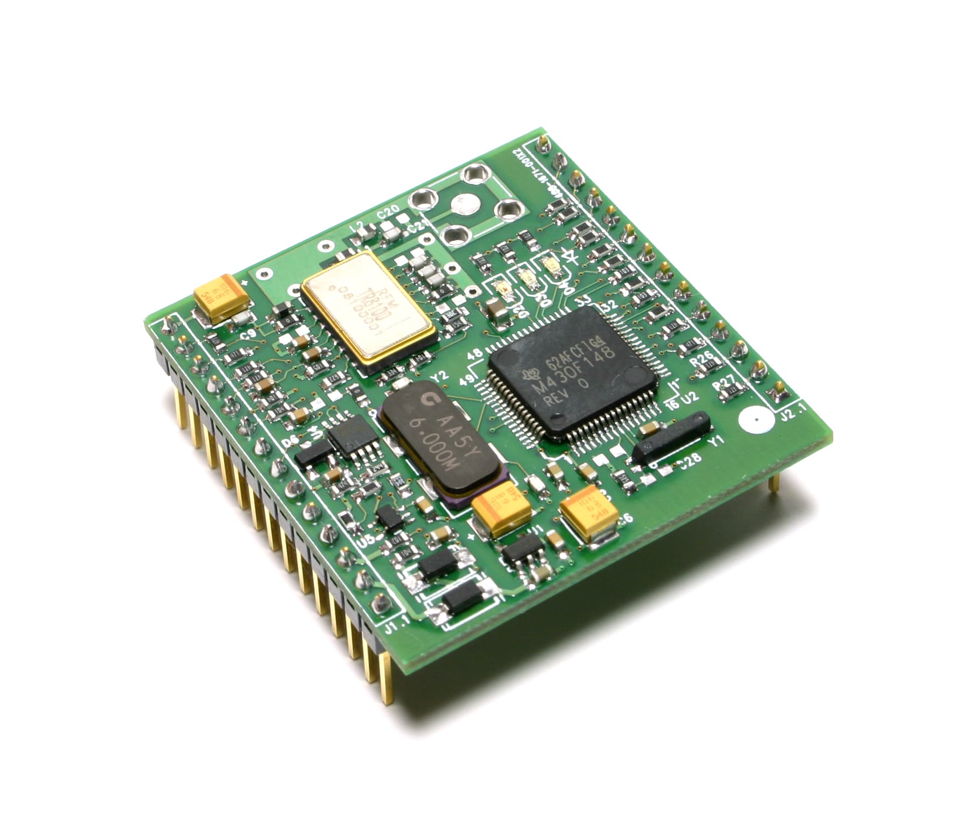
Click to zoom
Application Details
- Equipment Class
- DTS - Digital Transmission System
- Date of Grant
- May 15, 2006
- Application Purpose
- Original Equipment
- Date of Application
- May 15, 2006
- Equipment Note
- Remote Transceiver Module
- Frequency Range
- 916.50000000 - 916.50000000
- Country
- United States
Documents & Files
Document Text
Text extracted from the exhibit documents filed with the FCC. Open a document above to read the original.
Users Manual
1 ® DM2200- 916VM The DM2200-916VM is a 916.5 MHz transceiver module designed for wireless industrial sensor ap - plications. The transceiver module is equipped with two ADC inputs, three digital inputs, two digital outputs and a serial port. The communication range of the DM2200-916VM in an “open field” envi - ronment is typically 600 meters/hop. The DM2200-916VM combines RFM’s low-current ASH radio technology with low-power microprocessor technology to achieve very long battery life. The DM2200-916VM employs RFM’s VersaMESH TM V2.0 mesh network protocol, which provides ro - bust wireless network routing, an integrated multitasking operating system, and an extensive appli - cation command set. The DM2200-916VM is certified under FCC 15.247 regulations. RatingValueUnits All I/O Pins Except VIN-0.3 to +4.0V Non-Operating Ambient Temperature Range-50 to +100 o C Absolute Maximum Ratings • RFM Multitasking VersaMESH TM V2.0 Network Protocol • Analog, Digital and Serial I/O Ports • 3 V, Very Low Current Operation plus Sleep Mode • FCC 15.247 Certified Electrical Characteristics CharacteristicSymNotesMinimumTypicalMaximumUnits Operating Frequencyf O 916.30916.70MHz Modulation TypeOOK on BPSK Spreading Code RF Encoded Data Transmission Rate9.6kb/s Receive Mode: Average Input Current, 5 Vdc VIN SupplyI R 4.5mA Pulse Input Signal for 10 -3 BER, 25°C -102dBm Transmit Mode: Peak Input Current, 5 Vdc VIN SupplyI TP 32mA Peak Transmitter Output PowerP O 10dBm Average Sleep Mode Input Current, 5 Vdc VIN SupplyI S 68μA Analog Input Measurement Range (12-bit ADC)0V DD V External Source Impedance to Analog Input10K Digital Output Source Current, 1K Load1mA Digital Output Sink Current, 1K Load1.2mA Serial Port Data Rate19.2kb/s Internal Power Supply Input Voltage Range3.114.0Vdc External Power Supply Voltage RangeV DD 2.93.7Vdc External Power Supply Voltage Ripple10mV P-P Operating Ambient Temperature RangeT A -40+85 o C 916.50 MHz Transceiver Module In Development DM2200-916VM Theory of Operation The major components of the DM2200-916VM include the TR8100 ASH transceiver and the TI MSP430F148 microcontroller. The TR8100 operates on 916.5 MHz, with a nominal output power of 10 mW. The MSP- 430F148 can operate referenced to either a 32.768 kHz or 6 MHz crystal. The MSP430F148 UART is used to provide a CMOS serial interface on connector J2. The microcontroller’s I/O pins are also available on connector J2 for external monitoring or control. Note that GP0 is dedicated to measuring the value of the received signal strength indicator (RSSI) circuit and should always be set as an analog input. The three LEDs on the transceiver module display RF communication activity. DM2200-916VM operation is based on RFM’s multi- tasking VersaMESH TM network protocol, which supports data and command transfers through both the serial in - terface and the RF channel. See theVersaMESH TM Pro - tocol User’s Guidefor further details. 2 56789104321 GNDVIN 11121314 VRENVDDTD0TD1TWSTCKRSTCFG0CFG1CFG2CFG3GND J1 1 2 3 4 5 6 7 8 9 10 11 12 13 14 J2 3 VDC GRN YEL RED TR8100 ASH Transceiver RSSI Low Voltage Reset TXMOD RXDATA CFGDAT CFGCLK 3 VDC Voltage Regulator DM2200 Block Diagram GND GP7 GP6 GP5 GP4 GP3 GP2 GP1 GP0/RSSI RTS CTS TXD RXD GND MSP430F148 Microcontroller CFG Figure 1 DM2200-916VM FCC Certification The DM2200-916VM is certified for operation under FCC Part 15 Rules, Section 15.247. When the DM2200-916VM is run from an off-board power supply (applied to J1-4), the supply voltage must be limited to a maximum of 3.7 Vdc, and the power supply voltage ripple must not exceed 10 mV P-P . FCC Labels and Notices A clearly visible label is required on the outside of the user’s (OEM) enclosure stating that this product con - tains a DM2200-916VM radio module, FCC ID: TE6-DM2200A. This device complies with Part 15 of the FCC rules. Operation is subject to the following two conditions: (1) this device may not cause harmful interference, and (2) this device must accept any interference received, in - cluding interference that may cause undesired opera - tion. WARNING:This device operates under Part 15 of the FCC rules. Any modification to this device, not ex- pressly authorized by RF Monolithics, Inc., may void the user’s authority to operate this device. DM2200-916VM Applications There are two ways to use the DM2200-916VM in an application. The transceiver module can be used with a companion application interface board, the IM2200. The IM2200 has provisions for powering the transceiver module from a USB cable, an external unregulated DC supply such as a 5 Vdc “wall” transformer, an external regulated 3 Vdc power supply, or an external battery. The IM2200 also provides the choice of UART, RS232, RS485 (single drop) or USB for a host computer serial interface. In addition, the IM2200 includes captured- screw terminal strips for connecting analog inputs, digi - tal logic inputs, digital logic outputs and form C relay outputs. Refer to the IM2200 data sheet for additional details. The DM2200-916VM can also be integrated into the user’s own application board. The DM2200-916VM pin descriptions are given in the Table on pages 4 and 5. The transceiver module pin-out locations are show in Figure 2, and the PCB layout for the mating connectors is shown in Figure 3. The operating range of the DM2200-916VM critically depends on the antenna being located properly. When using the standard DM2200-916VM antenna (RFM part number 400-1687-001), care should be taken to keep the antenna at least 0.5 inch away from the sides of its enclosure. The enclosure must be made from a plastic with low RF attenuation, such as fiberglass, PVC or ABS.Note: other antenna configurations are possible, but each new antenna configuration must be added to the DM2200-916VM FCC module certification before deployment.Contact RFM for details. The DM2200-916VM enclosure should be mounted so the antenna is at least 4 feet off the ground, and ideally 6 or more feet off the ground.…
Text truncated - open the document above for the full version.
External Photos
DM2200 M odule FCC Reference Photo #1
External Photos
DM2200 M odule FCC Reference Photo #3 (Standard Antenna)
ID Label/Location Info
F C C L a b e l L o c a t i o n D M 2 2 0 0 M o d u l e F C C I D : T E 6 - D M 2 2 0 0 A F C C L a b e l F o r m a t
Internal Photos
DM2200 M odule FCC Reference Photo #1
Internal Photos
6 MHzCrystal 32.768 kHzCrystal 3.0 VdcRegulator MSP430F148Microprocessor TR8100 ShieldedTransceiver Hybrid,916.5 MHz BPSK-OOKDigital Modulation DM2200 M odule FCC Reference Photo #2
Internal Photos
DM2200 M odule FCC Reference Photo #3 (Standard Antenna)
Test Setup Photos
Nemko USA FCC PART 15, SUBPART C Digital Transmission Systems EQUIPMENT: DM2200-916VM Test Report No.: 6L0188RUS1 Page 13 of 24 Test Setup Photograph
Contact Information
Applicant
Mark Tucker(Manager, Hardware Engineering Group)
Technical Contact
Nemko USA, Inc.David Light
[email protected]972-436-9600
802 N. Kealy · Lewisville, Texas · United States
Non-Technical Contact
Nemko USA, Inc.Pravin Patel
[email protected]972-436-9600
Test Firm
Nemko USA, Inc.Tom Tidwell
Technical Specifications
| # | Rule Parts | Frequency Range | Power Output |
|---|---|---|---|
| 1 | 15C | 916.5 MHz - 916.5 MHz | 10.00 mW |
Other Applications from Murata Electronics North America
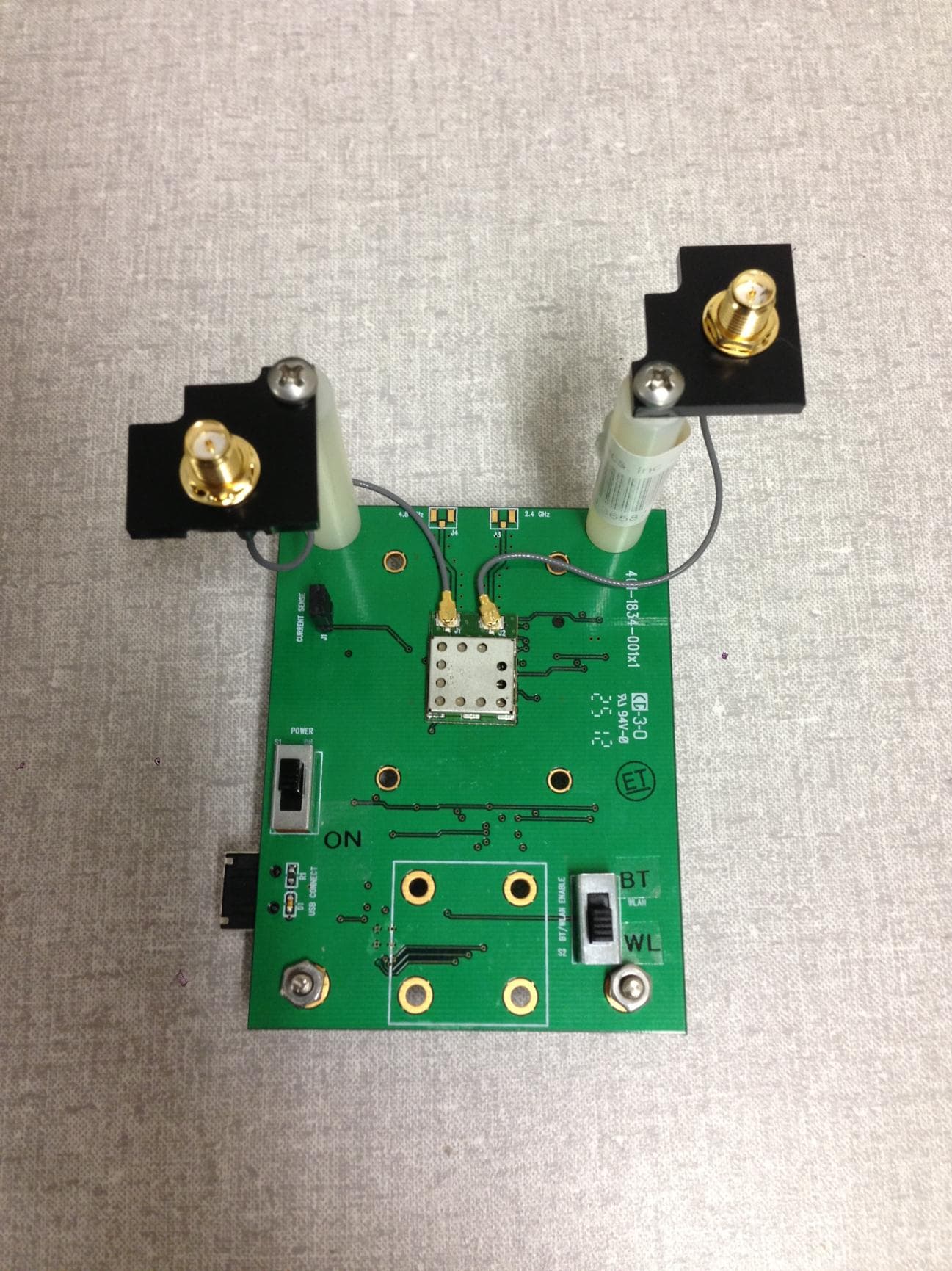
TE6-DRWLS1273L
Dec 16, 2012DR-WLS1273L-102
Equipment Class
DTS - Digital Transmission System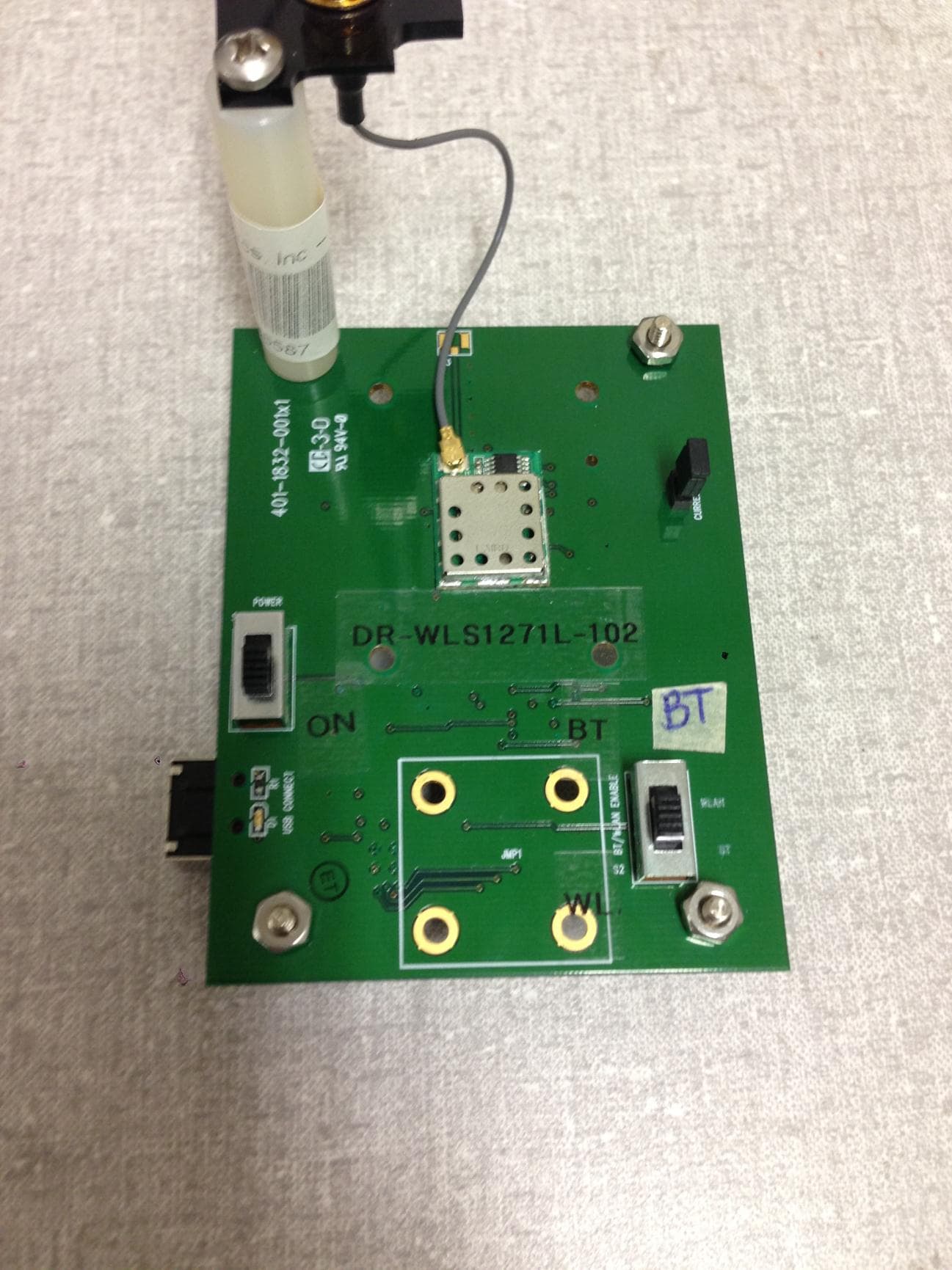
TE6-DRWLS1271L
Dec 16, 2012DR-WLS1271L-102
Equipment Class
DSS - Part 15 Spread Spectrum Transmitter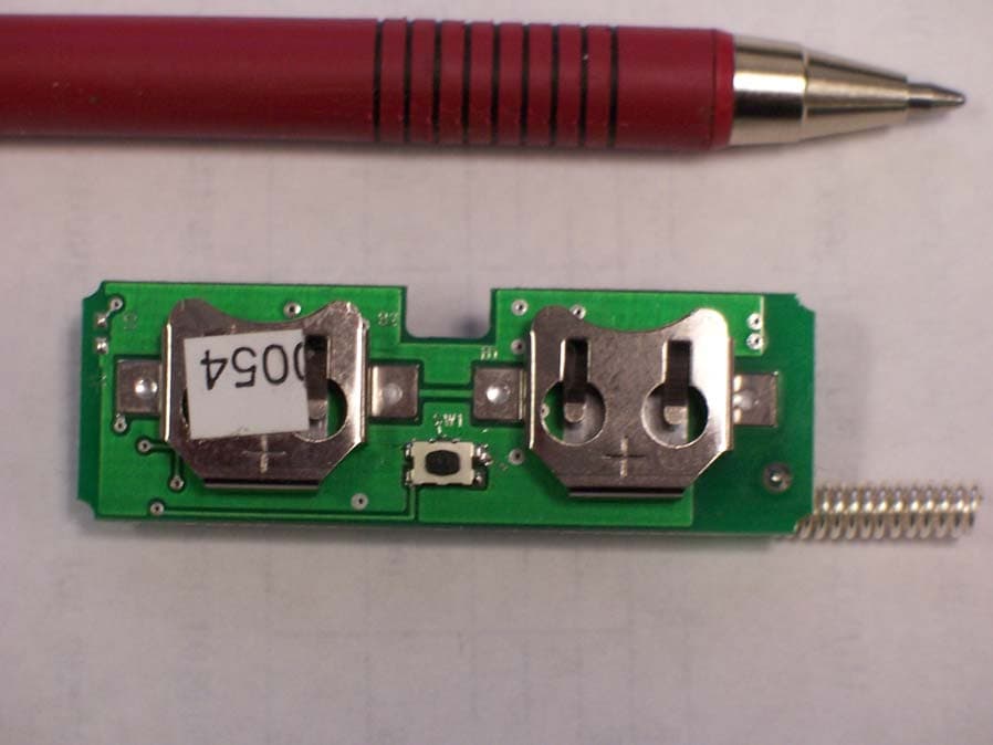
TE6CM2202N
Mar 16, 2006Remote Data Transmitter
Equipment Class
DXX - Part 15 Low Power Communication Device Transmitter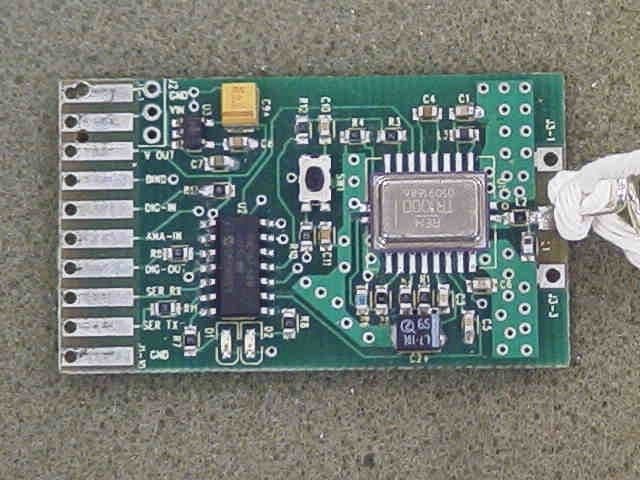
TE6DM1800
Dec 13, 2005TRANSMITTER-MODULAR APPROVAL
Equipment Class
DXX - Part 15 Low Power Communication Device Transmitter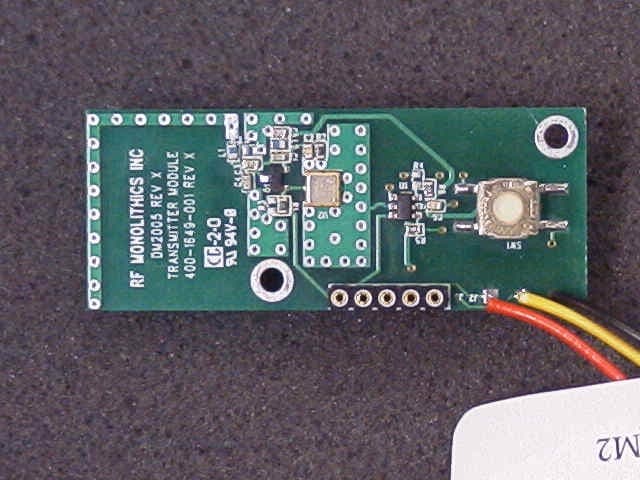
TE6-CM2201N
Nov 02, 2005TRANSCEIVER MODULE
Equipment Class
DXX - Part 15 Low Power Communication Device Transmitter