TE6CM2202NRemote Data Transmitter
Murata Electronics North America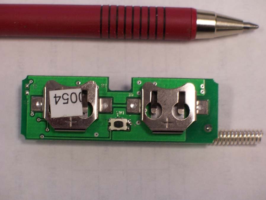
Click to zoom
Application Details
- Equipment Class
- DXX - Part 15 Low Power Communication Device Transmitter
- Date of Grant
- Mar 16, 2006
- Application Purpose
- Original Equipment
- Date of Application
- Mar 16, 2006
- Equipment Note
- Remote Data Transmitter
- Frequency Range
- 916.50000000 - 916.50000000
- Country
- United States
Documents & Files
Document Text
Text extracted from the exhibit documents filed with the FCC. Open a document above to read the original.
Users Manual
1 ® CM2202N RatingValueUnits All In put/Out put Pins-0.3 to +4.0V Non-Operating Am bi ent Tem per a ture Range-40 to +85 o C Ab so lute Max i mum Rat ings Cus tom Elec tri cal Char ac ter is tics CharacteristicSymNotesMinimumTypicalMaximumUnits Op er ating Fre quencyf O 916.30916.70MHz Mod u la tion TypeOOK En coded Data RF Trans mis sion Rate4.8kb/s Peak Radiated Field Strength (FCC OP-1)E O 20,000μV/m Bat teryBR1225 Dig i tal In put Logic High (Sen sor).85 VDDVDDV Dig i tal In put Logic Low (Sen sor)0.15 VDDV Op er ating Am bi ent Tem per a ture RangeT A -20+70 o C 916.50 MHz Transmitter Module The CM2202N is a 916.5 MHz trans mit ter mod ule de signed to mon i tor in dus trial alarm sen sors. Com mu ni ca tion range in an “open field” en vi ron ment is typ i cally 100 me ters. The CM2202N com bines RFM’s very low-cur rent SAW res o na tor sta bi lized trans mit ter tech nol ogy with low-power microcontroller tech nol ogy to achieve long bat tery life. The mod ule is com pat i ble with RFM’s miniMESH TM net work pro to col, which pro vides add-on “plug-and-play” multicast mesh net work rout ing. The CM2202N is cer ti fied for op er a tion un der FCC 15.249 reg u la tions. • In te grated Sen sor In ter face • Very Low Cur rent Op er a tion from 2 BR1225 Bat teries •Com pat i ble with RFM miniMESH TM Net work Pro to col • Ready-to-Use Mod ule 2 The ory of Op er a tion The ma jor com po nents of the CM2202N in clude an RFM SAW res o na tor sta bi lized trans mit ter and a Micro chip PIC12F635 microcontroller. The trans mit ter op er ates on a fre quency of 916.5 MHz, at a nom i nal out put power of 0.5 mW. The microcontroller gen er - ates “heart beat” trans mis sions pe ri od i cally, plus an im me di ate trans mis sion in the event of a sen sor alarm or test but ton ac ti va tion. The CM2202N is pow ered by 2 re place able 3 V BR1225 lith ium “coin cell” bat tery. The CM2202N is com pat i ble with RFM’s miniMESH TM net work pro to col, which pro vides add-on “plug-and- play” multicast mesh net work rout ing to im prove com - mu ni ca tion range and ro bust ness. FCC La bels and No tices This de vice com plies with Part 15 of the FCC rules. Op er a tion is sub ject to the fol low ing two con di tions: (1) this de vice may not cause harm ful in ter fer ence, and (2) this de vice must ac cept any in ter fer ence re - ceived, in clud ing in ter fer ence that may cause un de - sired op er a tion. A clearly vis i ble la bel is re quired on the out side of the user’s (OEM) en clo sure stat ing that this prod uct con - tains a CM2202N ra dio mod ule, FCC ID: TE6-CM2202N. WARNING: This de vice op er ates un der Part 15 of the FCC rules. Any mod i fi ca tion to this de vice, not ex- pressly au tho rized by RF Monolithics, Inc., may void the user’s au thor ity to op er ate this de vice. + + Test Button SAW Resonator CM2202N Sensor Transmitter Block Diagram Power Su pply is 2 3V BR1225 "Coin Cell" Batteries Tuning J2-2 J2-3 J2-1 J2-5 J2-4 Figure 1 PinNameDescription J2-1GNDThis pad is the ground return for the ex ter nal alarm sen sor. J2-2SENSORThis pad is a logic in put driven by the ex ter nal alarm sen sor. J2-3SNR PowerThis pad is the +3V power supply for the ex ter nal alarm sen sor. J2-4PclkThis pad is used to pro gram the microcontroller. No con nec tion should be made to it in nor mal op er a tion. J2-5VDDThis pad is used to pro gram the microcontroller. No con nec tion should be made to it in nor mal op er a tion. 3 Pin and Pad De scrip tions 4 Figure 2 Note 1: La ser mark on shield top with FCC ID and made in Phil ip pines. Note 2: Place la bel with bar code and al pha nu meric se rial num ber. Note 3: Place la bel with bat tery ori en ta tion. Note: Spec i fi ca tions sub ject to change with out no tice. file: CM2202.vp, 031006 rev
Cover Letter(s)
3/16/06 To Whom It May Concern: RF Monolithics Inc. would like to apply for Limited Modular FCC approval. This letter is our request for such according to FCC public notice DA 00- 1407. Modular Transmitter Requirements Modular Transmitter Requirements Manufacturer Clarification •1) The modular transmitter must have its own RF shielding. This is intended to ensure that the module does not have to rely upon the shielding provided by the device into which it is installed in order for all modular transmitter emissions to comply with Part 15 limits. It is also intended to prevent coupling between the RF circuitry of the module and any wires or circuits in the device into which the module is installed. Such coupling may result in non-compliant operation. The transmitter is complete with its own rf shielding. The shield is permanently attached to the module’s PCB •2) The modular transmitter must have buffered data inputs (if such inputs are provided). This is intended to ensure that the module will comply with Part 15 requirements in the event of excessive data rates or over- modulation conditions. The module has a buffered amplifier input for the data input pins on the TX chip. •3) The modular transmitter must have its own power supply regulation. This is intended to ensure that the module will comply with Part 15 requirements regardless of the design of the power supplying circuitry in the device into which the module is installed. The module operates on two “coin” battery cells. The battery holder is permanently attached to the module. •4) The modular transmitter must comply with the requirements of Section 15.203 - the antenna must either be permanently attached or employ a “unique” antenna coupler (at all connections between the module and the antenna, including the cable). The “professional installation” provision of this Section may not be applied to modules. Please note that Section 15.204(c) also applies to modules - any antenna used with the module must be approved with the module, The antenna is permanently soldered to the PCB. The antenna is a ¼ wavelength wire formed into a coil. There is no antenna connector provided on the PCB. either at the time of initial authorization or through a Class II permissive change. 5) The modular transmitter must be tested in a stand-alone configuration, i.e., the antenna, AC or DC power, and data input/output lines must be connected to the module, but the module must not be inside another device during testing. This is intended to demonstrate that the module is capable of complying with Part 15 emission limits regardless of the device into which it is eventually installed. Unless the transmitter module will be battery powered, it must comply with the AC line conducted requirements found in Section 15.207. AC or DC power lines and data input/output lines connected to the module must not contain ferrites, unless they will be marketed with the module (see Section 15.27(a)). The length of these lines shall be the length typical of actual usage or, if that length is unknown, at least 10 centimeters to insure that there is no coupling between the case of the module and supporting equipment. Any accessories, peripherals, or support equipment connected to the module during testing shall be unmodified or commercially available (see Section 15.31(i)). The module was tested as a stand-alone device. There are no AC, DC, or I/O lines. The only connection provided is data I/I through the header. •6) The modular transmitter must be labeled with its own FCC ID number, and, if the FCC ID is not visible when the module is installed inside another device, then the outside of the device into which the module is installed must also display a label referring to the enclosed module. This exterior label can use wording such as the The modular transmitter is inscribed with its own unique FCC ID. Instruction is given in the OEM manual as to labeling requirements. following: “Contains Transmitter Module FCC ID: XYZMODEL1” or “Contains FCC ID: XYZMODEL1.” Any similar wording that expresses the same meaning may be used. The Grantee may either provide such a label, an example of which must be included in the application for equipment authorization, or, must provide adequate instructions along with the module which explain this requirement. In the latter case, a copy of these instructions must be included in the application for equipment authorization. •7) The modular transmitter must comply with any specific rule or operating requirements applicable to the transmitter and the manufacturer must provide adequate instructions along with the module to explain any such requirements. A copy of these instructions must be included in the application for equipment authorization. For example, only cordless phones are permitted to operate under Section 15.233, thus, a module authorized under this Section would be limited to use in cordless phones and the instructions provided with the device must explain this limitation. The module meets all of the requirements of FCC Part 15, Subpart C. The device operates specifically under 15.249. •8) In the case of a modular transceiver, the modular approval policy only applies to the transmitter portion of such devices. Pursuant to Section 15.101(b), the receiver portion will either be subject to Verification, or it will not be subject to any authorization requirements (unless it is a Scanning Receiver, in which case it is also subject to Certification, The device is not a transceiver but is a transmitter. pursuant to Section 15.101(a)). •9) FCC Rules in Sections 2.1091, 2.1093 and specific Sections of Part 15, including 15.319(i), 15.407(f), 15.253(f) and 15.255(g), require that Unlicensed PCS, UNII and millimeter wave devices perform routine environmental evaluation for RF Exposure to demonstrate compliance. In addition, spread spectrum transmitters operating under Section 15.247 are required to address RF Exposure compliance in accordance with Sect…
Text truncated - open the document above for the full version.
ID Label/Location Info
F F C C C C I I D D : : T T E E 6 6 C C M M 2 2 2 2 0 0 2 2 N N I I C C : : X X X X X X X X X X - - C C 0 0 1 1 M M o o d d e e l l : : C C M M 2 2 2 2 0 0 2 2 F F C C C C I I D D : : T T E E 6 6 C C M M 2 2 2 2 0 0 2 2 N N I I C C : : X X X X X X X X X X - - C C 0 0 1 1 M M o o d d e e l l : : C C M M 2 2 2 2 0 0 2 2 N N
Internal Photos
THERE ARE NO COMPONENTS UNDER BATTERY HOLDERS.
Operational Description
CM2202N Transmitter 1.0 Description The CM2202N Transmitter is a battery-powered device using 2 BR1225 3V lithium batteries in parallel. The transmitter is OOK modulated at a data rate of 4800 bits/sec by the PICF635 processor on a nominal carrier frequency of 916.5 MHz. The transmitter is frequency stabilized using a SAW. The CM2202N transmitter is programmed to transmit a data packet every 6 hours in a random interval. Test packets are transmitted when the test button is pushed. When the SENSOR signal goes high alarm packets are transmitted in rapid intervals. Each unit is programmed with a unique electronic serial number (ESN). 2.0 Operation Procedure For test purposes, the units provided are programmed to operate as follows. 2.1 Install Batteries making sure the + side faces up. 2.2 Pressing SW1 button once will place the transmitter in the CW mode. 2.3 Pressing SW1 again will place the transmitter in a pulse mode. 2.4 Pressing SW1 a third time will turn the transmitter off. 3.0 Interface J2-1 GND J2-2 SENSOR input and VPP used for programming the processor J2-3 POWER to Sensor board and PDAT programming pin J1-4 PCLK programming pin J1-5 VDD Push button 4.0 Label The FCC ID will be laser printed on the shield as indicated on the assembly drawing using 8.5 font. 5.0 Warnings Batteries should be installed with + side up. Batteries installed backwards will not hurt the unit but the unit will not operate.
Test Report
Nemko Test Report: 6L0093RUS1 Applicant: RF Monolithics 4441 Sigma Road USA, TX 75244 USA Equipment Under Test: CM2202N (E.U.T.) In Accordance With: FCC Part 15, Subpart C, 15.249 For 900 MHz Transmitters Tested By: Nemko USA Inc. 802 N. Kealy Lewisville, Texas 75057-3136 Authorized By: Kevin Rose, Senior Wireless Engineer Date: March 16, 2006 Nemko USA, Inc. FCC PART 15, SUBPART C FOR 900 MHz TRANSMITTERS EQUIPMENT: CM2202N TEST REPORT NO.: 6L0093RUS1 Page 2 of 16 Table Of Contents Section 1. Summary Of Test Results ............................................................................3 Section 2. General Equipment Specification ...............................................................5 Section 3. Radiated Emissions ......................................................................................7 Section 4.Test Equipment List ......................................................................................13 ANNEX A TEST DIAGRAMS ....................................................................................14 Nemko USA, Inc. FCC PART 15, SUBPART C FOR 900 MHz TRANSMITTERS EQUIPMENT: CM2202N TEST REPORT NO.: 6L0093RUS1 Page 3 of 16 Section 1. Summary Of Test Results Manufacturer: RF Monolithics Model No.: CM2202N Serial No.: None General: All measurements are traceable to national standards. These tests were conducted on a sample of the equipment for the purpose of demonstrating compliance with FCC Part 15.249. All tests were conducted using measurement procedure ANSI C63.4-2003. Radiated Emissions were made on an open area test site. New Submission Production Unit Class II Permissive Change Pre-Production Unit THIS TEST REPORT RELATES ONLY TO THE ITEM(S) TESTED. THE FOLLOWING DEVIATIONS FROM, ADDITIONS TO, OR EXCLUSIONS FROM THE TEST SPECIFICATIONS HAVE BEEN MADE. See “ Summary of Test Data”. NVLAP LAB CODE: 100426-0 Nemko USA Inc. authorizes the above named company to reproduce this report provided it is reproduced in its entirety and for use by the company’s employees only. Any use which a third party makes of this report, or any reliance on or decisions to be made based on it, are the responsibility of such third parties. Nemko USA Inc. accepts no responsibility for damages, if any, suffered by any third party as a result of decisions made or actions based on this report. This report applies only to the items tested. Nemko USA, Inc. FCC PART 15, SUBPART C FOR 900 MHz TRANSMITTERS EQUIPMENT: CM2202N TEST REPORT NO.: 6L0093RUS1 Page 4 of 16 Summary Of Test Data NAME OF TEST PARA. NO. RESULT Conducted Emissions 15.207 NA Radiated Emissions 15.249 Complies Footnotes For N/A’s: The device is battery powered. The device was tested with a fresh battery. Nemko USA, Inc. FCC PART 15, SUBPART C FOR 900 MHz TRANSMITTERS EQUIPMENT: CM2202N TEST REPORT NO.: 6L0093RUS1 Page 5 of 16 Section 2. General Equipment Specification Frequency Range: 916.5 MHz (± 200 kHz) Operating Frequency(ies) of Sample: 916.5 MHz Tunable Bands: N/A Number of Channels: One Channel Spacing: NA User Frequency Adjustment: None Integral Antenna Yes No Nemko USA, Inc. FCC PART 15, SUBPART C FOR 900 MHz TRANSMITTERS EQUIPMENT: CM2202N TEST REPORT NO.: 6L0093RUS1 Page 6 of 16 Theory of Operation The CM2202N is a 916.5 MHz transmitter module designed to monitor industrial alarm sensors. Communication range in an “open field” environment is typically 100 meters. The CM2202N combines RFM’s very low-current SAW resonator stabilized transmitter technology with low- power microcontroller technology to achieve long battery life. System Diagram Nemko USA, Inc. FCC PART 15, SUBPART C FOR 900 MHz TRANSMITTERS EQUIPMENT: CM2202N TEST REPORT NO.: 6L0093RUS1 Page 7 of 16 Section 3. Radiated Emissions NAME OF TEST: Radiated Emissions PARA. NO.: 15.249 TESTED BY: David Light DATE: 3/13/06 Minimum Standard: Para no. 15.249 (a) The field strengths shall not exceed the following: Fundamental (MHz) Field Strength (mV/m) Field Strength (dBμV) Harmonic (mV/m) Harmonic (dBμV) 902-928 50 94 0.5 54 (b) Field strength limits are specified at a distance of 3 metres. (c) Emissions radiated outside of the specified frequency bands, except for harmonics, shall be attenuated by at least 50 dB below the level of the fundamental or to the general radiated limits of 15.209 whichever is the less attenuation. (d) ...for frequencies above 1000 MHz, the above field strength limits are based on average limits. However, the peak field strength of any emission shall not exceed the maximum permitted average limits specified above by more than 20 dB under any condition of modulation. Test Results: Complies Measurement Data: See attached table. Nemko USA, Inc. FCC PART 15, SUBPART C FOR 900 MHz TRANSMITTERS EQUIPMENT: CM2202N TEST REPORT NO.: 6L0093RUS1 Page 8 of 16 Test Data - Radiated Emissions Page 1 of 1 Job No.:6l0093Date: 3/13/2006 Specification:15.249Temperature(°C): 22 Tested By:David LightRelative Humidity(%) 45 E.U.T.: Configuration: Sample Number:1 Location:AC 3RBW:1 MHz Detector Type:PeakVBW:1 MHz Antenna:993Directional Coupler:#N/A Pre-Amp:1016Cable #1:1484 Filter:#N/ACable #2:1485 Receiver:1036Cable #3:#N/A Attenuator #1#N/ACable #4:#N/A Attenuator #2:#N/AMixer:#N/A Additional equipment: 759760791 Measurement Uncertainty: +/- 3.6 dB Meter Reading (dBuV) Antenna Factor (dB) Cable Loss (dB) Corrected Reading (dBuV/m) Detector / Polarity 916.582.224.01.824.383.794Peak/Vertical 916.570.024.01.824.371.594Peak/Horizontal 1833.046.327.22.932.144.37454Peak/Vertical 2749.546.529.43.732.746.97454Peak/Vertical 3666.057.230.53.632.359.074Peak/Vertical 3666.051.230.53.632.353.054Average/Vertical 4582.547.032.34.132.351.17454Peak/Vertical 5499.043.233.64.733.647.97454Peak/Vertical 6415.541.335.15.235.146.57454Peak/Vertical 7332.041.035.85.235.846.27454Peak/Vertical 8248.541.037.35.733.250.87454Peak/Vertical 9165.041.337.05.734.849.2Peak/Vertical 3666.050.030.53.632.351.874Peak/Horizontal 3666.044.030.53.632.345.854Average/Horizontal Spectrum…
Text truncated - open the document above for the full version.
Contact Information
Applicant
Mark Tucker(Manager, Hardware Engineering Group)
Technical Contact
Nemko USA, Inc.David Light
[email protected]972-436-9600
802 N. Kealy · Lewisville, Texas · United States
Non-Technical Contact
Nemko USA, Inc.Pravin Patel
[email protected]972-436-9600
Test Firm
Nemko USA, Inc.Tom Tidwell
Technical Specifications
| # | Rule Parts | Frequency Range | Power Output |
|---|---|---|---|
| 1 | 15C | 916.5 MHz - 916.5 MHz | - |
Other Applications from Murata Electronics North America
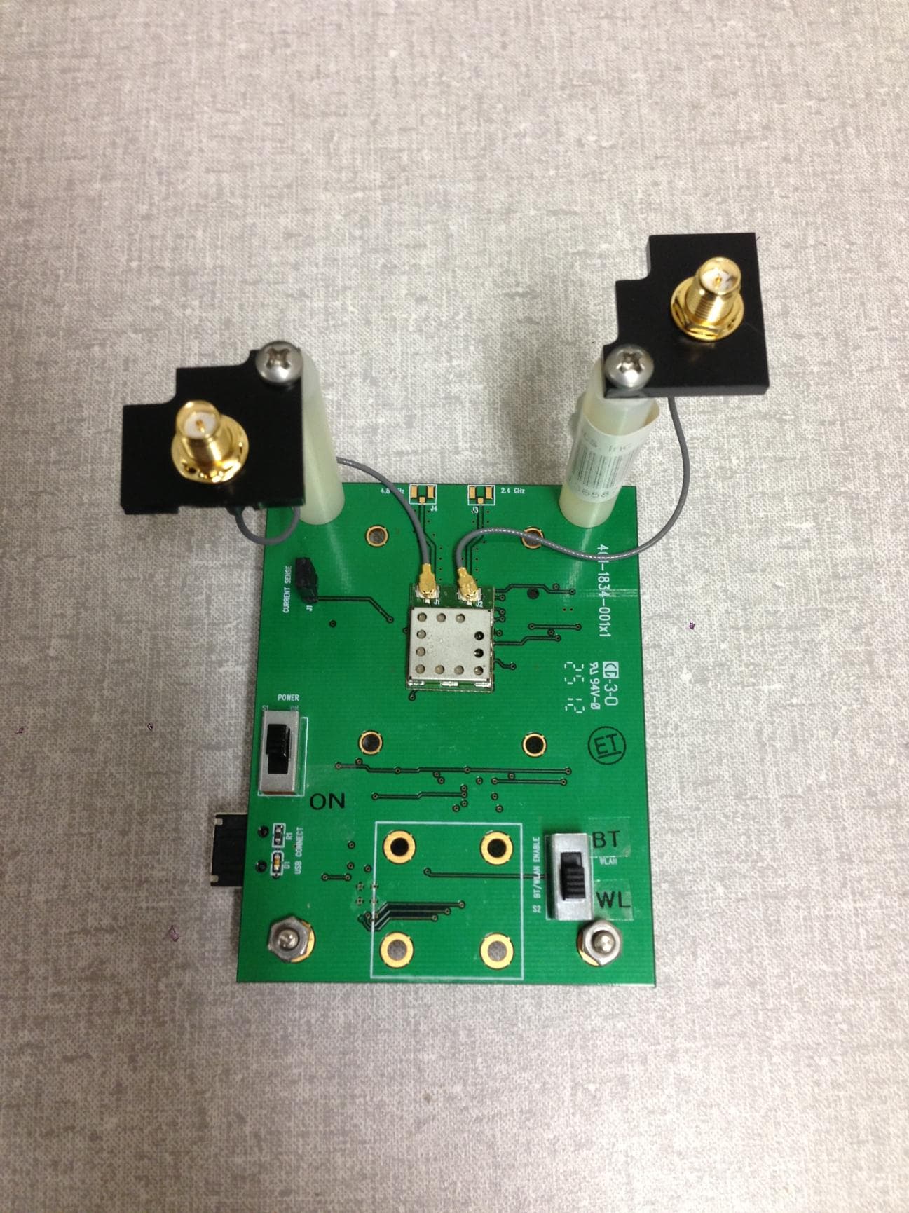
TE6-DRWLS1273L
Dec 16, 2012DR-WLS1273L-102
Equipment Class
DTS - Digital Transmission System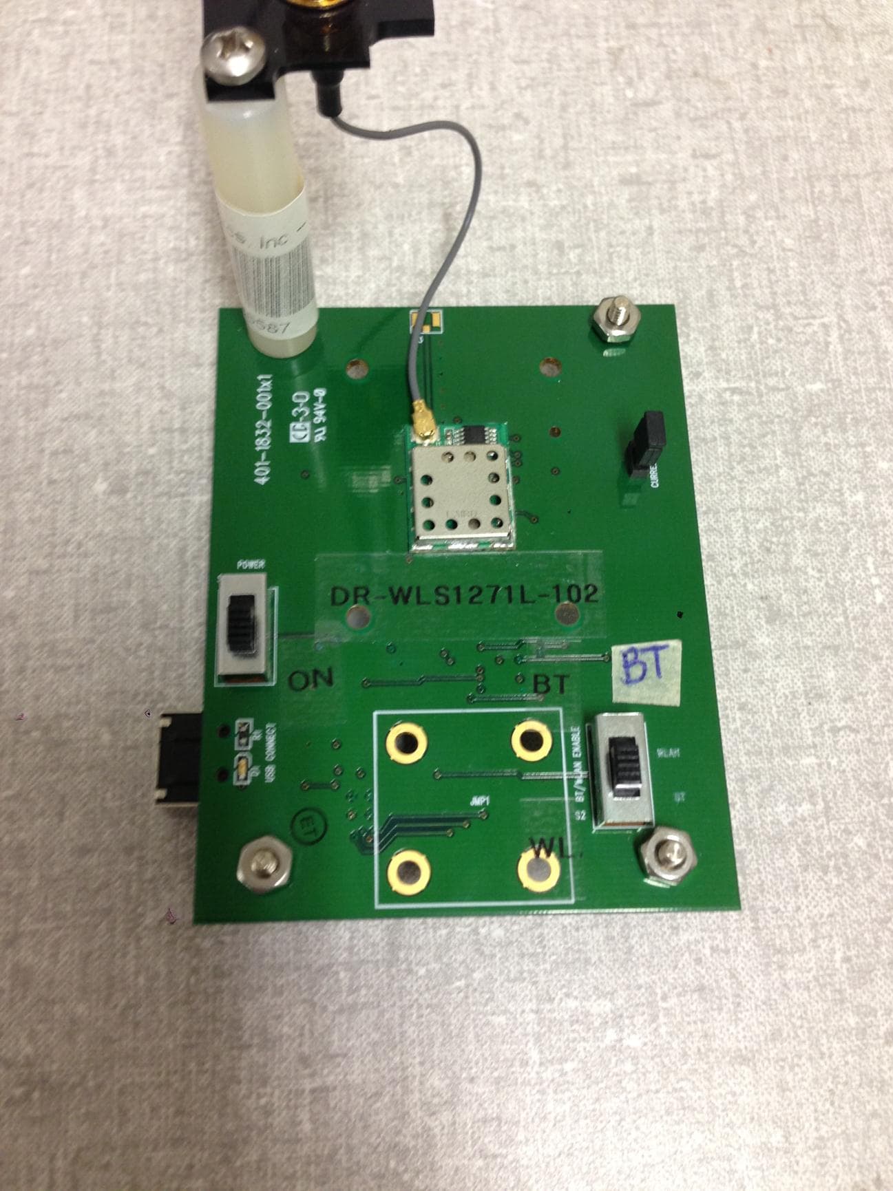
TE6-DRWLS1271L
Dec 16, 2012DR-WLS1271L-102
Equipment Class
DSS - Part 15 Spread Spectrum Transmitter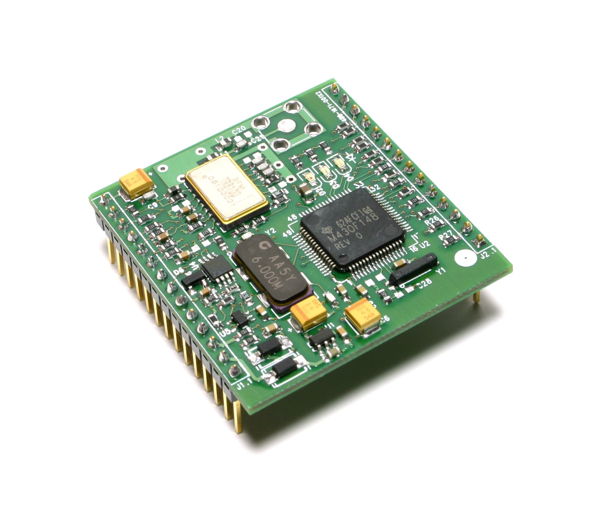
TE6-DM2200A
May 15, 2006Remote Transceiver Module
Equipment Class
DTS - Digital Transmission System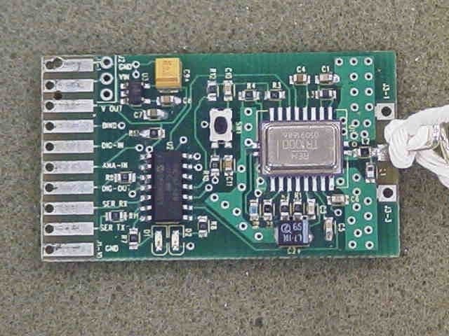
TE6DM1800
Dec 13, 2005TRANSMITTER-MODULAR APPROVAL
Equipment Class
DXX - Part 15 Low Power Communication Device Transmitter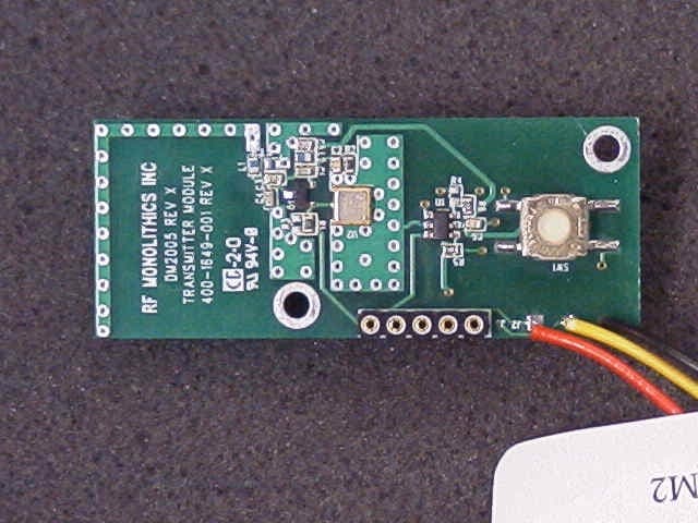
TE6-CM2201N
Nov 02, 2005TRANSCEIVER MODULE
Equipment Class
DXX - Part 15 Low Power Communication Device Transmitter