TE7RE230V2AC750 Wi-Fi Range Extender, AC1200 Wi-Fi Range Extender
TP-Link Technologies Co., Ltd.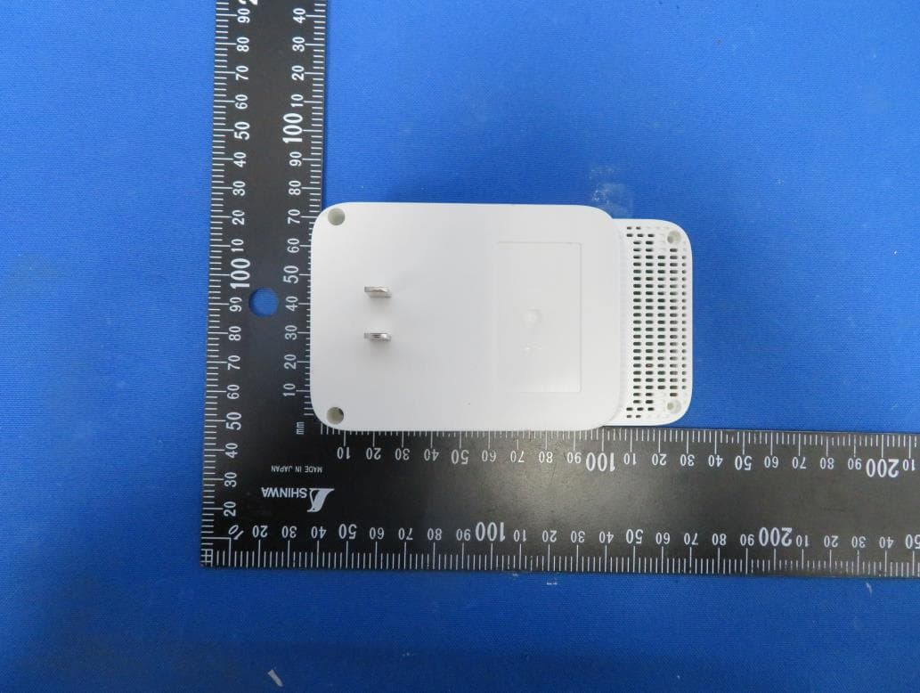
Click to zoom
Application Details
- Equipment Class
- DTS - Digital Transmission System
- Date of Grant
- Jan 13, 2021
- Application Purpose
- Original Equipment
- Date of Application
- Jan 11, 2021
- Equipment Note
- AC750 Wi-Fi Range Extender, AC1200 Wi-Fi Range Extender
- Frequency Range
- 2412.00000000 - 2462.00000000
- Country
- China
Documents & Files
Document Text
Text extracted from the exhibit documents filed with the FCC. Open a document above to read the original.
Users Manual
© 2020 TP-Link 1910012912 REV2.0.0 AC750 Wi-Fi Range Extender RE230 User Guide Contents About This Guide 1 Chapter 1 Get to Know About Your Extender 2 1. 1. Product Overview. . . . . . . . . . . . . . . . . . . . . . . . . . . . . . . . . . . . . . . . . . . . . . . . . . . . . . . . . . . . 3 1. 2. Appearance . . . . . . . . . . . . . . . . . . . . . . . . . . . . . . . . . . . . . . . . . . . . . . . . . . . . . . . . . . . . . . . . . 3 1. 2. 1. LED Explanation. . . . . . . . . . . . . . . . . . . . . . . . . . . . . . . . . . . . . . . . . . . . . . . . . . . . . . . 3 1. 2. 2. Button Description . . . . . . . . . . . . . . . . . . . . . . . . . . . . . . . . . . . . . . . . . . . . . . . . . . . . 4 Chapter 2 Set Up Internet Connection 5 2. 1. Power on the Extender. . . . . . . . . . . . . . . . . . . . . . . . . . . . . . . . . . . . . . . . . . . . . . . . . . . . . . . 6 2. 2. Set Up the Extender . . . . . . . . . . . . . . . . . . . . . . . . . . . . . . . . . . . . . . . . . . . . . . . . . . . . . . . . . 6 2. 2. 1. Method 1: Via the TP-Link Tether App. . . . . . . . . . . . . . . . . . . . . . . . . . . . . . . . . . 6 2. 2. 2. Method 2: Via a Web Browser. . . . . . . . . . . . . . . . . . . . . . . . . . . . . . . . . . . . . . . . . . 8 2. 2. 3. Method 3: Via the WPS Button. . . . . . . . . . . . . . . . . . . . . . . . . . . . . . . . . . . . . . . .12 Chapter 3 OneMesh with Seamless Roaming 15 3. 1. What‘s a OneMesh Network. . . . . . . . . . . . . . . . . . . . . . . . . . . . . . . . . . . . . . . . . . . . . . . . .16 3. 2. How to Set Up a OneMesh Network . . . . . . . . . . . . . . . . . . . . . . . . . . . . . . . . . . . . . . . . .17 3. 2. 1. Method 1: Via the TP-Link Tether App. . . . . . . . . . . . . . . . . . . . . . . . . . . . . . . . .17 3. 2. 2. Method 2: Via a Web Browser. . . . . . . . . . . . . . . . . . . . . . . . . . . . . . . . . . . . . . . . .18 3. 3. Remove Extender from OneMesh Network. . . . . . . . . . . . . . . . . . . . . . . . . . . . . . . . . .19 3. 3. 1. Method 1: Via the TP-Link Tether App. . . . . . . . . . . . . . . . . . . . . . . . . . . . . . . . .19 3. 3. 2. Method 2: Via a Web Browser. . . . . . . . . . . . . . . . . . . . . . . . . . . . . . . . . . . . . . . . .19 Chapter 4 TP-Link Cloud Service 21 4. 1. Register a TP-Link ID. . . . . . . . . . . . . . . . . . . . . . . . . . . . . . . . . . . . . . . . . . . . . . . . . . . . . . . .22 4. 2. Change Your TP-Link ID Information. . . . . . . . . . . . . . . . . . . . . . . . . . . . . . . . . . . . . . . . .22 4. 3. Manage the User TP-Link IDs . . . . . . . . . . . . . . . . . . . . . . . . . . . . . . . . . . . . . . . . . . . . . . .23 4. 3. 1. Add TP-Link ID to Manage the Extender . . . . . . . . . . . . . . . . . . . . . . . . . . . . . .24 4. 3. 2. Remove TP-Link ID(s) from Managing the Extender . . . . . . . . . . . . . . . . . . .24 4. 4. Manage the Extender via the TP-Link Tether App. . . . . . . . . . . . . . . . . . . . . . . . . . . .25 Chapter 5 Customize Your Network 26 5. 1. Check Internet Status. . . . . . . . . . . . . . . . . . . . . . . . . . . . . . . . . . . . . . . . . . . . . . . . . . . . . . .27 5. 2. Configure Wireless Network . . . . . . . . . . . . . . . . . . . . . . . . . . . . . . . . . . . . . . . . . . . . . . . .28 5. 3. Change LAN Settings. . . . . . . . . . . . . . . . . . . . . . . . . . . . . . . . . . . . . . . . . . . . . . . . . . . . . . .30 5. 4. Specify DHCP Server Settings. . . . . . . . . . . . . . . . . . . . . . . . . . . . . . . . . . . . . . . . . . . . . .30 5. 5. Set High Speed Mode. . . . . . . . . . . . . . . . . . . . . . . . . . . . . . . . . . . . . . . . . . . . . . . . . . . . . . .31 5. 6. Set Access Control . . . . . . . . . . . . . . . . . . . . . . . . . . . . . . . . . . . . . . . . . . . . . . . . . . . . . . . . .32 5. 7. Adjust Wi-Fi Coverage . . . . . . . . . . . . . . . . . . . . . . . . . . . . . . . . . . . . . . . . . . . . . . . . . . . . . .34 Chapter 6 More Features of Your Extender 36 6. 1. Use Your Extender as a Wireless Adapter. . . . . . . . . . . . . . . . . . . . . . . . . . . . . . . . . . . .37 6. 2. Transform Your Existing Wired Network to a Wireless One . . . . . . . . . . . . . . . . . . .37 6. 2. 1. To Set Up the Extender as an Access Point . . . . . . . . . . . . . . . . . . . . . . . . . . .37 6. 2. 2. To Connect Your Wireless Devices to the Extender via WPS. . . . . . . . . . .38 Chapter 7 Manage Your Extender 41 7. 1. Set System Time . . . . . . . . . . . . . . . . . . . . . . . . . . . . . . . . . . . . . . . . . . . . . . . . . . . . . . . . . . .42 7. 2. Control LEDs . . . . . . . . . . . . . . . . . . . . . . . . . . . . . . . . . . . . . . . . . . . . . . . . . . . . . . . . . . . . . . .43 7. 3. Set Power Schedule . . . . . . . . . . . . . . . . . . . . . . . . . . . . . . . . . . . . . . . . . . . . . . . . . . . . . . . .43 7. 4. Upgrade the Firmware . . . . . . . . . . . . . . . . . . . . . . . . . . . . . . . . . . . . . . . . . . . . . . . . . . . . . .44 7. 4. 1. Online Upgrade . . . . . . . . . . . . . . . . . . . . . . . . . . . . . . . . . . . . . . . . . . . . . . . . . . . . . .45 7. 4. 2. Local Upgrade . . . . . . . . . . . . . . . . . . . . . . . . . . . . . . . . . . . . . . . . . . . . . . . . . . . . . . .45 7. 5. Backup and Restore Configuration Settings. . . . . . . . . . . . . . . . . . . . . . . . . . . . . . . . .45 7. 6. Reboot the Extender. . . . . . . . . . . . . . . . . . . . . . . . . . . . . . . . . . . . . . . . . . . . . . . . . . . . . . . .47 7. 7. Change Login Password . . . . . . . . . . . . . . . . . . . . . . . . . . . . . . . . . . . . . . . . . . . . . . . . . . . .48 7. 8. Check System Log . . . . . . . . . . . . . . . . . . . . . . . . . . . . . . . . . . . . . . . . . . . . . . . . . . . . . . . . .48 FAQ 50 1 About This Guide This guide is a complement to Quick Installation Guide. The Quick Installation Guide provides instructions for quick inter…
Text truncated - open the document above for the full version.
Users Manual
46 Chapter 7Manage Your Extender 1. Visit http://tplinkrepeater.net, and log in with your TP-Link ID or the password you set for the extender. 2. Go to Settings > System Tools > Backup & Restore. • To backup configuration settings: Click BACK UP to save a copy of the current settings to your local computer. A ‘.bin’ file of the current settings will be stored on your computer. • To restore previous settings from a saved file: 1. Click BROWSE to locate the backup configuration file stored on your computer, and click RESTORE. 2. Wait a few minutes for the restore and reboot. Note: During the restore process, do not power off or reset the extender. • To restore configuration settings In Factory Default Restore, click RESTORE to restore all configuration settings to default values, except your login and cloud account information. Note: During the restore process, do not power off or reset the extender. • To reset the extender to factory default settings: 47 Chapter 7Manage Your Extender 1. Click FACTORY RESTORE to reset the extender. 2. Wait a few minutes for the reset and reboot. Note: 1. During the reset process, do not power off or reset the extender. 2. We strongly recommend you backup the current configuration settings before resetting the extender. 7 6 Reboot the Extender You can reboot your extender to clear cache and enhance running performance if needed. 1. Visit http://tplinkrepeater.net, and log in with your TP-Link ID or the password you set for the extender. 2. Go to Settings > System Tools > Reboot. • To reboot the extender Click REBOOT and wait a few minutes. • To set up reboot schedule Enable Reboot Schedule and set the corresponding settings. 48 Chapter 7Manage Your Extender 7 7 Change Login Password The account management feature allows you to change your login username and password of the web management webpage. 1. Visit http://tplinkrepeater.net, and log in with your TP-Link ID or the password you set for the extender. 2. Go to Settings > System Tools > Change Login Password. 3. Enter the old password. Then enter the new password twice (case-sensitive) and click S AV E. 4. Use the new password for future logins. 7 8 Check System Log If the extender is not working properly, you can save the system log and send it to our technical support team. 1. Visit http://tplinkrepeater.net, and log in with your TP-Link ID or the password you set for the extender. 2. Go to Settings > System Tools > System Log. • To save the system log locally: 1. Choose the type and level of the system log as needed. 2. Click SAVE LOG to save the system logs to a local disk. 49 Chapter 7Manage Your Extender 50 FAQ Q1 How to reset the extender to its factory default settings? • With the extender powered on, use a pin to press the Reset button for 1 second. The extender will reboot. • Log in to the extender’s web management page. Go to Settings > System Tools > Backup & Restore and click FACTORY RESTORE. Q2 What should I do if I forget my login password? • If you are using a TP-Link ID to log in, or you have enabled the Password Recovery feature of the extender, click Forgot Password? on the login page and then follow the instructions to reset it. • Refer to FAQ > Q1 to reset the extender, and then visit http://tplinkrepeater.net to create a new login password. Note: The extender must be reconfigured after a reset to access the internet. Please note down your login password for future logins. Q3 What should I do if I forget my wireless password? In Range Extender mode, the extender shares the same wireless passwords as those of your host networks. In Access Point mode, please connect your computer to the extender using an Ethernet cable and follow the steps below: 1. Visit http://tplinkrepeater.net, and log in with the password you set for the extender. 2. Go to Wireless to retrieve or reset your wireless password. Q4 What should I do if I can’t access the web management page? This can happen for a variety of reasons. Please try the methods below to log in again. • If your computer is wirelessly connected, make sure that you have connected to the extender’s SSID. • If your computer is connected via an Ethernet cable, please make sure that the connection is stable. • Make sure your computer is configured as Obtain an IP address automatically and Obtain DNS server address automatically. • Verify that http://tplinkrepeater.net is correctly entered in the web browser and press Enter. • Use the IP address to access the extender. The default IP is 192.168.0.254. If the extender is connected to the router, you should go to your router’s DHCP client list to obtain the extender’s current IP address. 51 • Reset the extender and try again. Q5 I have enabled wireless MAC filter, wireless access control, or access control list (ACL) on my router What should I do before configuring the extender? When a device connects through the extender to your router, the MAC address of the device shown on the router is translated to another MAC address. If your router’s MAC filter, wireless access control, or ACL is enabled, the devices connected to the extender cannot get an IP address from the extender and cannot access the Internet. To solve this problem, please follow the steps below: 1. Log in to your router and disable the MAC filter, wireless access control or ACL. Note: For more information about how to disable your router’s MAC filter, wireless access control or ACL, please refer to your router’s user guide. 2. Power on your extender, and run the Quick Setup to configure your extender. 3. Connect all of your devices to the extended network, and make sure the router’s Link LED remains lit. 4. On your router, add all the Online Devices’ MAC addresses to your router’s MAC filter table. 5. Enable the router’s MAC filter, wireless access control, or ACL to complete the configuration. 52 FCC compliance information statement Product Name: AC750 Wi-Fi Range Extender Model Number: RE230 Responsible Party: TP-Link USA Corporation, …
Text truncated - open the document above for the full version.
Cover Letter(s)
Attestation Letter Federal Communications Commission Authorization and Evaluation Division We Name: TP-Link Technologies Co., Ltd. Address: Building 24 (floors 1,3,4,5) and 28 (floors1-4), Central Science and Technology Park, Nanshan Shenzhen, 518057 China Declare that the device does not support channel 12 ~ 13 in 2.4GHz band and any non-US channels in all the operational mode(s) for the following product. Product: AC750 Wi-Fi Range Extender AC1200 Wi-Fi Range Extender FCC ID: TE7RE230V2 Model: RE230, RE330 Brand: tp-link Sincerely, _________________ Name: Huang Jing Position: Regulatory Compliance Manager Date: 2020-12-28
Cover Letter(s)
Confidentiality Request Letter Federal Communications Commission Authorization and Evaluation Division FCC ID: TE7RE230V2 Confidentiality Request Pursuant to Sections 0.457 and 0.459 of the Commission’s Rules, we hereby request confidential treatment of information accompanying this application as outlined below: 1. Block Diagram 2. Schematics 3. Operational Description The above materials contain trade secrets and proprietary information not customarily released to the public. The public disclosure of these matters might be harmful to the applicant and provide unjustified benefits to its competitors. The applicant understands that pursuant to Rule 0.457, disclosure of this application and all accompanying documentation will not be made before the date of the Grant for this application. Sincerely, _________________ Name: Huang Jing Position: Regulatory Compliance Manager Date: 2020-12-28
Cover Letter(s)
Declaration of Authorization We Name: TP-Link Technologies Co., Ltd. Address: Building 24 (floors 1,3,4,5) and 28 (floors1-4), Central Science and Technology Park, Nanshan Shenzhen, 518057 China Declare that: Name Representative of agent: Marlin Chen Agent Company name: MRT Technology (Suzhou) Co., Ltd Address: D8 Building, Youxin Industrial Park, No.2 Tian'edang Rd., Wuzhong Economic Development Zone City: Suzhou Country: China is authorized to apply for Certification of the following product(s): Product: AC750 Wi-Fi Range Extender AC1200 Wi-Fi Range Extender FCC ID: TE7RE230V2 Model: RE230, RE330 Brand: tp-link Sincerely, _________________ Name: Huang Jing Position: Regulatory Compliance Manager Date: 2020-12-28
External Photos
Report No.: 2008RSU036-UE 1 of 3 EUT Photograph (1) EUT Photo (2) EUT Photo Report No.: 2008RSU036-UE (3) EUT Photo (4) EUT Photo Report No.: 2008RSU036-UE (5) EUT Photo (6) EUT Photo
ID Label/Location Info
Label RE230 RE330 Label Location
Internal Photos
Report No.: 2008RSU036-UE 1 of 4 EUT Photograph (1) EUT Photo (2) EUT Photo Report No.: 2008RSU036-UE (3) EUT Photo (4) EUT Photo Report No.: 2008RSU036-UE (5) EUT Photo (6) EUT Photo 2.4G Ant 0 5G Ant 1 2.4G Ant 1 5G Ant 0 Report No.: 2008RSU036-UE (7) EUT Photo (8) EUT Photo
RF Exposure Info
MRT Technology (Suzhou) Co., Ltd Report No.: 2008RSU036-U5 Phone: +86-512-66308358 Report Version: V01 Web: www.mrt-cert.com Issue Date: 12-30-2020 Page Number: 1 of 8 RF Exposure Evaluation Declaration FCC ID: TE7RE230V2 APPLICANT: TP-Link Technologies Co., Ltd. Application Type: Certification Product: AC750 Wi-Fi Range Extender AC1200 Wi-Fi Range Extender Model No.: RE230, RE330 Trademark: tp-link FCC Classification: Digital Transmission System (DTS) Unlicensed National Information Infrastructure (NII) Test Date: December 22, 2020 Reviewed By: ( Kevin Guo ) Approved By: ( Robin Wu ) The test results relate only to the samples tested. The test results shown in the test report are traceable to the national/international standards through the calibration of the equipment and evaluated measurement uncertainty herein. The test report shall not be reproduced except in full without the written approval of MRT Technology (Suzhou) Co., Ltd. Report No.: 2008RSU036-U5 Page Number: 2 of 8 Revision History Report No. Version Description Issue Date Note 2008RSU036-U5 Rev. 01 Initial Report 12-30-2020 Valid Report No.: 2008RSU036-U5 Page Number: 3 of 8 CONTENTS Description Page 1. General Information ............................................................................................................ 4 1.1. Applicant ............................................................................................................................... 4 1.2. Manufacturer ........................................................................................................................ 4 1.3. Testing Facility ..................................................................................................................... 4 2. PRODUCT INFORMATION ................................................................................................... 5 2.1. Feature of Equipment under Test ..................................................................................... 5 2.2. Description of Available Antennas..................................................................................... 5 3. RF Exposure Evaluation ..................................................................................................... 6 3.1. Limits ..................................................................................................................................... 6 3.2. Test Result of RF Exposure Evaluation ........................................................................... 7 Appendix A - EUT Photograph ................................................................................................... 8 Report No.: 2008RSU036-U5 Page Number: 4 of 8 1. General Information 1.1. Applicant TP-Link Technologies Co., Ltd. Building 24 (floors 1,3,4,5) and 28 (floors1-4), Central Science and Technology Park, Nanshan Shenzhen, 518057 China 1.2. Manufacturer TP-Link Technologies Co., Ltd. Building 24 (floors 1,3,4,5) and 28 (floors1-4), Central Science and Technology Park, Nanshan Shenzhen, 518057 China 1.3. Testing Facility Test Site – MRT Suzhou Laboratory Laboratory Location (Suzhou - Wuzhong) D8 Building, No.2 Tian’edang Rd., Wuzhong Economic Development Zone, Suzhou, China Laboratory Location (Suzhou - SIP) 4b Building, Liando U Valley, No.200 Xingpu Rd., Shengpu Town, Suzhou Industrial Park, China Laboratory Accreditations A2LA: 3628.01 CNAS: L10551 FCC: CN1166 ISED: CN0001 VCCI: R-20025, G-20034, C-20020, T-20020 Test Site – MRT Shenzhen Laboratory Laboratory Location (Shenzhen) 1G, Building A, Junxiangda Building, Zhongshanyuan Road West, Nanshan District, Shenzhen, China Laboratory Accreditations A2LA: 3628.02 CNAS: L10551 FCC: CN1284 ISED: CN0105 Test Site – MRT Taiwan Laboratory Laboratory Location (Taiwan) No. 38, Fuxing 2nd Rd., Guishan Dist., Taoyuan City 333, Taiwan (R.O.C.) Laboratory Accreditations TAF: L3261-190725 FCC: 291082, TW3261 ISED: TW3261 Report No.: 2008RSU036-U5 Page Number: 5 of 8 2. PRODUCT INFORMATION 2.1. Feature of Equipment under Test Note: There is the same hardware design, PCB layout between the models, different models and product names for different marketing requirements. Only RE230 (Product name: AC750 Wi-Fi Range Extender) was selected for final tests. 2.2. Description of Available Antennas Antenna Type Frequency Band (MHz) T X Paths Max Antenna Gain (dBi) Beamforming Directional Gain (dBi) CDD Directional Gain (dBi) For Power For PSD PCB Antenna 2412 ~ 2462 2 2.0 -- 2.0 5.01 5150 ~ 5850 2 3.0 6.01 3.0 6.01 Note 1: The EUT supports Cyclic Delay Diversity (CDD) mode, and CDD signals are correlated. If all antennas have the same gain, G ANT , Directional gain = G ANT + Array Gain, where Array Gain is as follows. • For power spectral density (PSD) measurements on all devices, Array Gain = 10 log (N ANT / N SS ) dB; • For power measurements on IEEE 802.11 devices, Array Gain = 0 dB for N ANT ≤ 4; Note 2: The EUT also supports Beam Forming mode, and the Beam Forming support 802.11n/ac, not include 802.11a/b/g. BF Directional gain = G ANT + 10 log (N ANT ). Note 3: All information is provided by the manufacturer. Product Name AC750 Wi-Fi Range Extender AC1200 Wi-Fi Range Extender Model No. RE230, RE330 Brand Name: tp-link Wi-Fi Specification: 802.11a/b/g/n/ac Report No.: 2008RSU036-U5 Page Number: 6 of 8 3. RF Exposure Evaluation 3.1. Limits According to FCC 1.1310: The criteria listed in the following table shall be used to evaluate the environment impact of human exposure to radio frequency (RF) radiation as specified in 1.1307(b) LIMITS FOR MAXIMUM PERMISSIBLE EXPOSURE (MPE) Frequency Range (MHz) Electric Field Strength (V/m) Magnetic Field Strength (A/m) Power Density (mW/cm 2 ) Average Time (Minutes) (A) Limits for Occupational/ Control Exposures 300-1500 -- -- f/300 6 1500-100,000 -- -- 5 6 (B) Limits for General Population/ Uncontrolled Exposures 300-1500 -- -- f/1500 6 1500-100,000 -- -- 1 30 f= Frequency in MHz Calculation Formula: Pd = (Pout*G)/(4*pi*r…
Text truncated - open the document above for the full version.
Test Report
MRT Technology (Suzhou) Co., Ltd Report No.: 2008RSU036-U2 Phone: +86-512-66308358 Report Version: V01 Web: www.mrt-cert.com Issue Date: 12-30-2020 Page Number: 1 of 142 FCC ID: TE7RE230V2 Applicant: TP-Link Technologies Co., Ltd. Application Type: Certification Product: AC750 Wi-Fi Range Extender AC1200 Wi-Fi Range Extender Model No.: RE230, RE330 Brand Name: tp-link FCC Classification: Digital Transmission System (DTS) FCC Rule Part(s): Part 15 Subpart C (Section 15.247) Test Procedure(s): ANSI C63.10-2013 Test Date: August 30 ~ September 22, 2020 Reviewed By: ( Kevin Guo ) Approved By: ( Robin Wu ) MEASUREMENT REPORT FCC PART 15C / WLAN 802.11b/g/n The test results relate only to the samples tested. This equipment has been shown to be capable of compliance with the applicable technical standards as indicated in the measurement report and was tested in accordance with the measurement procedures specified in ANSI C63.10-2013. Test results reported herein relate only to the item(s) tested. The test report shall not be reproduced except in full without the written approval of MRT Technology (Suzhou) Co., Ltd. Report No.: 2008RSU036-U2 Page Number: 2 of 142 Revision History Report No. Version Description Issue Date Note 2008RSU036-U2 Rev. 01 Initial Report 12-30-2020 Valid Report No.: 2008RSU036-U2 Page Number: 3 of 142 CONTENTS Description Page 1. General Information ............................................................................................................... 5 1.1. Applicant ...................................................................................................................... 5 1.2. Manufacturer ................................................................................................................ 5 1.3. Testing Facility .............................................................................................................. 5 2. PRODUCT INFORMATION ...................................................................................................... 6 2.1. Equipment Description ................................................................................................. 6 2.2. Product Specification Subjective to this Report ............................................................ 6 2.3. Working Frequencies for this report .............................................................................. 7 2.4. Description of Available Antennas ................................................................................ 7 2.5. Test Mode .................................................................................................................... 8 2.6. Configuration of Test System ....................................................................................... 8 2.7. Test System Details ..................................................................................................... 8 2.8. Description of Test Software ......................................................................................... 8 2.9. Duty Cycle .................................................................................................................... 9 2.10. EMI Suppression Device(s)/Modifications ..................................................................... 9 2.11. Test Environment Condition .......................................................................................... 9 3. ANTENNA REQUIREMENTS................................................................................................. 10 4. TEST EQUIPMENT CALIBRATION DATE ............................................................................. 11 5. MEASUREMENT UNCERTAINTY ......................................................................................... 15 6. TEST RESULT ....................................................................................................................... 16 6.1. Summary .................................................................................................................... 16 6.2. 6dB Bandwidth Measurement ..................................................................................... 17 6.2.1. Test Limit ................................................................................................................ 17 6.2.2. Test Procedure used ............................................................................................... 17 6.2.3. Test Setting ............................................................................................................. 17 6.2.4. Test Setup .............................................................................................................. 17 6.2.5. Test Result .............................................................................................................. 18 6.3. Output Power Measurement ....................................................................................... 21 6.3.1. Test Limit ................................................................................................................ 21 6.3.2. Test Procedure Used .............................................................................................. 21 6.3.3. Test Setting ............................................................................................................. 21 6.3.4. Test Setup .............................................................................................................. 21 6.3.5. Test Result .............................................................................................................. 22 6.4. Power Spectral Density Measurement ........................................................................ 23 Report No.: 2008RSU036-U2 Page Number: 4 of 142 6.4.1. Test Limit ................................................................................................................ 23 6.4.2. Test Procedure Used ..........................................................................…
Text truncated - open the document above for the full version.
Test Report
Report No.: 2008RSU036-U2 Page Number: 40 of 142 802.11n-HT40 Out-of-Band Emissions -Ant 0 Channel 09 (2452MHz) 100kHz PSD Reference Level High Band Edge Spurious Emission Report No.: 2008RSU036-U2 Page Number: 41 of 142 802.11b Out-of-Band Emissions -Ant 1 Channel 01 (2412MHz) 100kHz PSD Reference Level Low Band Edge Spurious Emission Channel 06 (2437MHz) 100kHz PSD Reference Level Spurious Emission Report No.: 2008RSU036-U2 Page Number: 42 of 142 802.11b Out-of-Band Emissions -Ant 1 Channel 11 (2462MHz) 100kHz PSD Reference Level High Band Edge Spurious Emission Report No.: 2008RSU036-U2 Page Number: 43 of 142 802.11g Out-of-Band Emissions -Ant 1 Channel 01 (2412MHz) 100kHz PSD Reference Level Low Band Edge Spurious Emission Channel 06 (2437MHz) 100kHz PSD Reference Level Spurious Emission Report No.: 2008RSU036-U2 Page Number: 44 of 142 802.11g Out-of-Band Emissions -Ant 1 Channel 11 (2462MHz) 100kHz PSD Reference Level High Band Edge Spurious Emission Report No.: 2008RSU036-U2 Page Number: 45 of 142 802.11n-HT20 Out-of-Band Emissions -Ant 1 Channel 01 (2412MHz) 100kHz PSD Reference Level Low Band Edge Spurious Emission Channel 06 (2437MHz) 100kHz PSD Reference Level Spurious Emission Report No.: 2008RSU036-U2 Page Number: 46 of 142 802.11n-HT20 Out-of-Band Emissions -Ant 1 Channel 11 (2462MHz) 100kHz PSD Reference Level High Band Edge Spurious Emission Report No.: 2008RSU036-U2 Page Number: 47 of 142 802.11n-HT40 Out-of-Band Emissions -Ant 1 Channel 03 (2422MHz) 100kHz PSD Reference Level Low Band Edge Spurious Emission Channel 06 (2437MHz) 100kHz PSD Reference Level Spurious Emission Report No.: 2008RSU036-U2 Page Number: 48 of 142 802.11n-HT40 Out-of-Band Emissions -Ant 1 Channel 09 (2452MHz) 100kHz PSD Reference Level High Band Edge Spurious Emission Report No.: 2008RSU036-U2 Page Number: 49 of 142 6.6. Radiated Spurious Emission Measurement 6.6.1.Test Limit All out of band emissions appearing in a restricted band as specified in Section 15.205 of the Title 47 CFR must not exceed the limits shown in Table per Section 15.209. FCC Part 15 Subpart C Paragraph 15.209 Frequency [MHz] Field Strength [uV/m] Measured Distance [Meters] 0.009 - 0.490 2400/F (kHz) 300 0.490 - 1.705 24000/F (kHz) 30 1.705 - 30 30 30 30 - 88 100 3 88 - 216 150 3 216 - 960 200 3 Above 960 500 3 6.6.2.Test Procedure Used ANSI C63.10 - 2013 - Section 11.11 & 11.12 ANSI C63.10 - 2013 - Section 6.3 (General Requirements) ANSI C63.10 - 2013 - Section 6.4 (Standard test method below 30MHz) ANSI C63.10 - 2013 - Section 6.5 (Standard test method above 30MHz to 1GHz) ANSI C63.10 - 2013 - Section 6.6 (Standard test method above 1GHz) 6.6.3.Test Setting Table 1 - RBW as a function of frequency Frequency RBW 9 ~ 150 kHz 200 ~ 300 Hz 0.15 ~ 30 MHz 9 ~ 10 kHz 30 ~ 1000 MHz 100 ~ 120 kHz > 1000MHz 1MHz Report No.: 2008RSU036-U2 Page Number: 50 of 142 Quasi-Peak Measurements below 1GHz 1. Analyzer center frequency was set to the frequency of the radiated spurious emission of interest 2. Span was set greater than 1MHz 3. RBW = as specified in Table 1 4. Detector = CISPR quasi-peak 5. Sweep time = auto couple 6. Trace was allowed to stabilize Peak Measurements above 1GHz 1. Analyzer center frequency was set to the frequency of the radia…
Text truncated - open the document above for the full version.
Contact Information
Applicant
Jing Huang(Regulatory Compliance Manager)
Technical Contact
MRT Technology (Suzhou) Co., LtdRobin Wu
[email protected]86-512-66308358
D8 Building, Youxin Industrial Park, · Suzhou · China
Non-Technical Contact
MRT Technology (Suzhou) Co., LtdRobin Wu
[email protected]86-512-66308358
Test Firm
MRT Technology (Suzhou) Co., Ltd.Mr. Marlin Chen
[email protected]+86-512-66308358
Technical Specifications
| # | Rule Parts | Frequency Range | Power Output |
|---|---|---|---|
| 1 | 15C | 2.41 GHz - 2.46 GHz | 152.40 mW |
Other Applications from TP-Link Technologies Co., Ltd.
TE7AX20V2
Dec 22, 2020AX1800 Dual-Band Wi-Fi 6 Router
Equipment Class
DTS - Digital Transmission System
TE7EAP620HD
Dec 17, 2020AX1800 Wireless Dual-Band Gigabit Ceiling Mount Access Point
Equipment Class
NII - Unlicensed National Information Infrastructure TX
TE7KP303V2
Dec 15, 2020Kasa Smart Wi-Fi Power Strip, 3-Outlet
Equipment Class
DTS - Digital Transmission System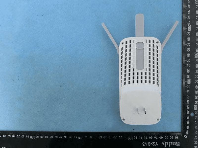
TE7RE550
Dec 03, 2020AC1750 Wi-Fi Range Extender, AC1900 MU-MIMO Wi-Fi Range Extender
Equipment Class
DTS - Digital Transmission System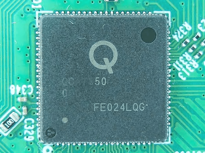
TE7WPA8631PV3
Nov 27, 2020AV1300 Gigabit Passthrough Powerline ac Wi-Fi Extender
Equipment Class
NII - Unlicensed National Information Infrastructure TX