TEB-HUNTGS10122Utility Meter Transceiver Module
Landis+Gyr Technologies, LLC
Click to zoom
Application Details
- Equipment Class
- DTS - Digital Transmission System
- Date of Grant
- Dec 06, 2011
- Application Purpose
- Original Equipment
- Date of Application
- Dec 06, 2011
- Equipment Note
- Utility Meter Transceiver Module
- Frequency Range
- 2405.00000000 - 2475.00000000
- Company
- Landis+Gyr Technologies, LLC
- Country
- United States
Documents & Files
Document Text
Text extracted from the exhibit documents filed with the FCC. Open a document above to read the original.
Users Manual
LANDIS+GYR CONFIDENTIAL INFORMATION Landis+Gyr Gridstream RF Enhanced kV2c Endpoint Data Sheet Publication: 98-1083 Rev AA Limitation on Warranties and Liability Information in this document is subject to change without notice. This manual or any part of it thereof may not be re- produced in any form unless permitted by contract or by written permission of Landis+Gyr. In no event will Landis+Gyr be liable for any incidental, indirect, special, or consequential damages (including lost prof- its) arising out of or relating to this publication or the information contained in it, even if Landis+Gyr has been advised, knew, or should have known of the possibility of such damages. © 2011 Landis+Gyr, Inc. All Rights Reserved Landis+Gyr Gridstream RF Enhanced kV2c Endpoint Quick Data Sheet Publication: 98-1083 Rev AA Revision History Modification DateRevisionDescriptionAuthor 12/5/2011AAWork in progressKim Utesch Landis+Gyr 6436 County Road 11 Pequot Lakes, MN 56472 Website: www.landisgyr.com E-mail: [email protected] Technical Support: 1-888-390-5733 © 2011 Landis+Gyr All rights reserved. Data Sheet98-1083 Rev AA3 Landis+Gyr Gridstream RF Enhanced kV2c Endpoint Data Sheet Endpoint Overview Landis+Gyr Gridstream RF Enhanced kV2c Endpoint Figure 1. kV2c Endpoint This communication module is not available as a stand alone product. To order a Gridstream RF Enhanced kV2c Endpoint, the Landis+Gyr kit number is 45-6100 with ZigBee or 45-6101 without ZigBee. The endpoint assembly contains: •High Speed GE kV2c Meter •Communications Module •Antenna Assembly CONTAINS FCC ID: TEB-HUNTSG10122 CONTAINS IC: 5931A-HUNTGS10122 MODEL 40-6100 XXXXXXXX Data SheetLandis+Gyr 498-1083 Rev AAData Sheet FCC Compliance Information Model: 40-6100 (Forms 1S, 2S, 9S, 12S, 16S, 45S) FCC ID:TEB-HUNTGS10122 Module: 10122 Industry Canada Under Industry Canada regulations, this radio transmitter may only operate using an antenna of a type and maximum (or lesser) gain approved for the transmitter by Industry Canada. To reduce potential radio interference to other users, the antenna type and its gain should be so chosen that the equivalent isotropically radiated power (e.i.r.p.) is not more than that necessary for successful communication. Cet appareillage numérique de la classe B répond à toutes les exigences de l'interférence canadienne causant des règlements d'équipement. L'opération est sujette aux deux conditions suivantes: (1) ce dispositif peut ne pas causer l'interférence nocive, et (2) ce dispositif doit accepter n'importe quelle interférence reçue, y compris l'interférence qui peut causer l'opération peu désirée. Pour réduire le risque d'interférer avec d'autres utilisateurs, le type d'antenne et son gain doivent être choisis de telle sorte que la Puissance Isotrope Rayonnée Equivalente (P.I.R.E) ne soit pas supérieure à celle autorisée pour une communication réussie. Compliance Statement (Part 15.19) This device complies with Part 15 of the FCC Rules. Operation is subject to the following two conditions: 1.This device may not cause harmful interference, and 2. This device must accept any interference received, including interference that may cause undesired operation. UWARNING: Changes or modifications not expressly approved by Landis+Gyr for compliance could void the user’s authority to operate the equipment. Endpoint Location To comply with FCC’s RF exposure limits for general population/uncontrolled exposure, the antenna(e) used for this transmitter must be installed to provide a separation distance of at least 20 cm from all persons and must not be collocated or operating in conjunction with any other antenna or transmitter. Endpoint Usage The Gridstream RF FOCUS AX Integrated endpoint will be used for residential and light commercial metering applications. The Gridstream RF FOCUS AX Integrated endpoint requires professional installation by qualified personnel. Landis+GyrData Sheet Data Sheet98-1083 Rev AA5 RF Interference This equipment has been tested and found to comply with the limits for a Class B digital device, pursuant to part 15 of the FCC Rules. These limits are designed to provide reasonable protection against harmful radio frequency energy and, if not installed and used in accordance with the instructions, may cause harmful interference to radio communications. However, there is no guarantee that interference will not occur in a particular installation. If this equipment does cause harmful interference to radio or television reception, which can be determined by turning the meter off, the user is encouraged to try to correct the interference by one or more of the following measures: 1.Re-orient or relocate the receiving antenna. 2.Increase the separation between the equipment and receiver. 3.Consult Landis+Gyr or an experienced radio/TC technician for help. Required Software To work with the endpoint, you need one of the following software tools: •Command Center version 5.5 or later. •RadioShop version XX or later •Endpoint Testing Manager version XX or later About the LAN ID The LAN ID is a unique identifier for each endpoint. It always displays in hex. Landis+Gyr provides the LAN address. You cannot change the LAN ID of a radio. Labels The endpoint includes the following labels. Figure 2. Label Identification MODEL 40-6100 XXXXXXXX XXXXXXXX GE #103X942001 ww/yy 40-6100 REV XX MODEL 40-6101 XXXXXXXX XXXXXXXX GE #103X942001 ww/yy 40-6101 REV XX Data SheetLandis+Gyr 698-1083 Rev AAData Sheet 1.LAN ID, includes programmed module part number (printed and barcoded) 2.Product ID (printed and barcoded) 3.FCC ID:TEB-HUNTGS10122 4.ICC ID: 5931A- HUNTGS10122 Features and Functions Using the GE High Speed kV2c Meter with the Gridstream RF kV2c Enhanced endpoint, you can: •Integrate the endpoint into all forms, classes and voltages of the GE kV2c meter. •Communicate via serial connection between the endpoint and the meter through the meter's provided interface. •Support all levels of meter passwords.…
Text truncated - open the document above for the full version.
Cover Letter(s)
6436 County Road 11 – Pequot Lakes, MN 56472 – Phone: 218.562.4877 – Fax: 218.562.4878 – www.hunttechnologies.com Date: October 4, 2011 Federal Communications Commission Equipment Authorization Branch 7435 Oakland Mills Rd. Columbia, MD 21046 Dear Sir or Madam: I hereby appoint Sam Wismer at Advanced Compliance Solutions, Inc. to act as our agent in the preparation of an application for equipment authorization of FCC ID: TEB‐HUNTGS10122 to the FCC Rules and Regulations. I certify that all exhibits contained within this filing properly describe the device or system for which authorization is sought. I further certify that appropriate arrangements have been made to assure that production units of this equipment bearing the name and FCC IDENTIFIER listed in this application will continue to comply with the Commission's requirements. I further certify by signature below that no party (per 47 CFR 1.2002(b)) to the application is subject to a denial of Federal benefits, including FCC benefits, pursuant to Section 5301 of the Anti‐Drug Abuse Act of 1988, 21 U.S.C. 853(a). This appointment also includes the authority to complete FCC Form 731 on our behalf and sign the application as an authorized agent. Sincerely, Name: Carl Jacobi Title: Quality Engineer
Cover Letter(s)
6436 County Road 11 – Pequot Lakes, MN 56472 – Phone: 218.562.4877 – Fax: 218.562.4878 – www.hunttechnologies.com CONFIDENTIALITY REQUEST Federal Communications Commission Date: October 4, 2011 Equipment Authorization Branch 7435 Oakland Mills Road Columbia, MD 21046 Gentlemen: Cellnet Technology, Inc. respectfully requests confidentiality of certain materials provided with the submission of the “Gridstream RF‐Enhanced GE kV2c Endpoint” under FCC ID: TEB‐HUNTGS10122 in accordance with FCC Regulations 0.459. The confidentiality request applies to the following exhibits contained in the filing: 11‐0031 ‐ System Block Diagram.pdf 11‐0031 – Schematics.pdf 11‐0031 ‐ Theory of Operation.pdf The “Gridstream RF‐Enhanced GE kV2c Endpoint” has been developed at considerable effort and expense by Hunt Technology, Inc. These items are considered as Trade Secrets and therefore public access to the proprietary material could possibly result in duplication of equipment that could severely damage the company's business advantage. I appreciate your assistance in this matter. Sincerely, Name: Carl Jacobi Title: Quality Engineer October 4, 2011
Cover Letter(s)
5015 B. U. Bowman Dr. Buford, GA 30518 June 2, 2011 ACS TCB 5015 B.U. Bowman Drive Buford, GA 30518 Re: FCC ID: TEB-HUNTGS10122 To Whom It May Concern: The following application is submitted on behalf of our client, Hunt Technologies, Inc., for evaluation of their model 10122 for certification under FCC Part 15.247 for a single modular approval. The 10122 module is a daughter board module, manufactured by Hunt Technologies, Inc. that plugs into a GE KV2C metrology circuit board. Model 10122 contains two separate radios: a 900 MHz ISM band frequency-hopping spread spectrum (FHSS) transceiver and a 2.4 MHz ISM band transceiver employing 802.15.4/ZigBee, each of which was evaluated separately to the corresponding rules and found to be in compliance. Both radios can transmit simultaneously therefore the device was also evaluated for radiated inter- modulation products and found to be in compliance. Sincerely, Sam Wismer Vice President, Technology Advanced Compliance Solutions, Inc.
Cover Letter(s)
Exhibit O: Modular Approval Questionnaire TEB-HUNTG10122 1. The modular transmitter must have its own RF shielding. This is intended to ensure that the module does not have to rely upon the shielding provided by the device into which it is installed in order for all modular transmitter emissions to comply with Part 15 limits. It is also intended to prevent coupling between the RF circuitry of the module and any wires or circuits in the device into which the module is installed. Such coupling may result in non-compliant operation. The GE10122 Universal RF module contains its own RF shielding as shown in Exhibit B - Internal Photos. As depicted in Exhibit E - Test Setup Photos, the unit was tested in a stand-alone configuration. The unit was mounted in the top portion of the GE KV2C meter housing, but only so that the antenna could be mounted in its proper location. This is the antenna location for all manufactured production units. The use of the GE meter housing did not provide any external shielding or filtering, so in effect it is a stand alone configuration. The housing used during testing is all plastic and glass (LCD display) and will be present in every configuration. 2. The modular transmitter must have buffered modulation/data inputs (if such inputs are provided) to ensure that the module will comply with Part 15 requirements under conditions of excessive data rates or over-modulation. The GE 10122 Universal RF module’s microprocessor communicates with the GEmeter to read the applicable data that it must transmit. It then provides modulation to the RF section. Therefore, the data rate of the communications between the GE10122 Universal RF module and the GE meter has no bearing on the data rate of the transmitted signal. In other words, there is no way for the S4e meter to make the GE 10122 Universal RF module transmit excessive data rates or over-modulate. 3. The modular transmitter must have its own power supply regulation. This is intended to ensure that the module will comply with Part 15 requirements regardless of the design of the power supplying circuitry in the device into which the module is installed. The GE 10122 Universal RF module requires a nominal 27VDC unregulated supply from the GE meter and regulates it down to 3.6VDC and then through further regulation to 3.3VDC. The regulated supplies are used by the RF circuit. The GE 10122 Universal RF module mounts inside of and connects to the GE meter, which is connected to the AC mains. The testing proves the GE 10122 Universal RF module, when connected to a representative compliant host connected to the AC mains, allows the host to remain compliant. The host used for testing was operated at 240 VAC, 60 Hz. 4. The modular transmitter must comply with the antenna requirements of Section 15.203 and 15.204(c). The antenna must either be permanently attached or employ a “unique” antenna coupler (at all connections between the module and the antenna, including the cable). Any antenna used with the module must be approved with the module, either at the time of initial authorization or through a Class II permissive change. The “professional installation” provision of Section 15.203 may not be applied to modules. The GE 10122 Universal RF module uses an external antenna. There is only one approved antenna and it was used during the testing for initial authorization as shown in Exhibit E - Test Setup Photos. The antenna connects to the module through a unique IPEX connector and is assembled at a Landis+Gyr facility when the module is mounted into the GE meter. 5. The modular transmitter must be tested in a stand-alone configuration, i.e., the module must not be inside another device during testing. This is intended to demonstrate that the module is capable of complying with Part 15 emission limits regardless of the device into which it is eventually installed. Unless the transmitter module will be battery powered, it must comply with the AC line conducted requirements found in Section 15.207. AC or DC power lines and data input/output lines connected to the module must not contain ferrites, unless they will be marketed with the module (see Section 15.27(a)). The length of these lines shall be length typical of actual use or, if that length is unknown, at least 10 centimeters to insure that there is no coupling between the case of the module and supporting equipment. Any accessories, peripherals, or support equipment connected to the module during testing shall be unmodified or commercially available (see Section 15.31(i)). The transmitter was tested in a stand-alone configuration per number 1 above. 6. The modular transmitter must be labeled with its own FCC ID number, and, if the FCC ID is not visible when the module is installed inside another device, then the outside of the device into which the module is installed must also display a label referring to the enclosed module. This exterior label can use wording such as the following: “Contains Transmitter Module FCC ID: XYZMODEL1” or “Contains FCC ID: XYZMODEL1.” Any similar wording that expresses the same meaning may be used. The Grantee may either provide such a label, an example of which must be included in the application for equipment authorization, or, must provide adequate instructions along with the module which explain this requirement. In the latter case, a copy of these instructions must be included in the application for equipment authorization. The FCC and IC IDs are contained on a label on the outside of the meter saying “Contains FCC ID: TEB-HUNTGS10122 Contains IC: 5931A-HUNTGS10122” 7. The modular transmitter must comply with any specific rule or operating requirements applicable to the transmitter and the manufacturer must provide adequate instructions along with the module to explain any such requirements. A copy of these instructions must be included in the application for equipment authorization. For example, there are very strict operational and timing requi…
Text truncated - open the document above for the full version.
External Photos
Exhibit B: GE 10122 Internal Photos. Front. Back.
ID Label/Location Info
Figure 1: Sample Label Figure 2: Sample Host Label
Internal Photos
Exhibit B: GE 10122 Internal Photos. Front. Front with Shields with shields removed. Back. FCC /IC Compliance Statement. FCC label placement.
RF Exposure Info
5015 B.U. Bowman Drive Buford, GA 30518 USA Voice: 770-831-8048 Fax: 770-831-8598 Certification Exhibit FCC ID: TEB-HUNTGS10122 IC: 5931A-HUNTGS10122 FCC Rule Part: 15.247 IC Radio Standards Specification: RSS-210 ACS Project Number: 11-0031 Manufacturer: Hunt Technologies, Inc. Model: 10122 RF Exposure Model: 10122 FCC ID: TEB-HUNTGS10122 IC: 5931A-HUNTGS10122 ACS Project: 11-0031 Advanced Compliance Solutions Page 2 General Information: Applicant: Hunt Technologies, Inc. ACS Project: 11-0031 Device Category: Mobile Environment: General Population/Uncontrolled Exposure Technical Information 900MHz: Antenna Type: Patch Antenna Gain: 2.15dBi Maximum Transmitter Conducted Power: 26.97dBm Maximum System EIRP: 29.12dBm, 816.6 mW Exposure Conditions: Greater than 20 centimeters Technical Information 2400MHz ZigBee: Antenna Type: PCB inverted-F Antenna Gain: 5.15dBi Maximum Transmitter Conducted Power: 21.06dBm Maximum System EIRP: 26.21 dBm, 417.8 mW Exposure Conditions: Greater than 20 centimeters MPE Calculation The Power Density (mW/cm 2 ) is calculated as follows: S = 2 4R PG Where: S = power density (in appropriate units, e.g. mW/cm2) P = power input to the antenna (in appropriate units, e.g., mW) G = power gain of the antenna in the direction of interest relative to an isotropic radiator R = distance to the center of radiation of the antenna (appropriate units, e.g., cm) MPE Calculator for Mobile Equipment Limits for General Population/Uncontrolled Exposure* 90426.970.60497.742.151.641200.162 240521.061.00127.645.153.273 200.083 Power De nsity (mW/cm^2) Dista nce (cm) Transmit Frequency (MHz) Radio Power (dBm) Power Density Limit (mW/Cm2) Radio Power (mW) Ante nna Gain (dBi) Antenna Gain (mW eq.) Installation Guidelines The installation manual should contain text similar to the following advising how to install the equipment to maintain compliance with the FCC RF exposure requirements: RF Exposure In accordance with FCC requirements of human exposure to radio frequency fields, the radiating element shall be installed such that a minimum separation distance of 20 centimeters will be maintained. Conclusion This device complies with the MPE requirements by providing adequate separation between the device, any radiating structure and the general population.
Test Report
5015 B.U. Bowman Drive Buford, GA 30518 USA Voice: 770-831-8048 Fax: 770-831-8598 Certification Test Report FCC ID: TEB-HUNTGS10122 IC: 5931A-HUNTGS10122 FCC Rule Part: 15.247 IC Radio Standards Specification: RSS-210 ACS Report Number: 11-0031.W06.22.A Manufacturer: Hunt Technologies, Inc. Model: 10122 Test Begin Date: February 1, 2011 Test End Date: February 24, 2011 Report Issue Date: October 4, 2011 FOR THE SCOPE OF ACCREDITATION UNDER LAB Code 200612-0 This report must not be used by the client to claim product certification, approval, or endorsement by NVLAP, NIST, or any agency of the Federal Government. Reviewed by: Kirby Munroe Director, Wireless Certifications ACS, Inc. This test report shall not be reproduced except in full. This report may be reproduced in part with prior written consent of ACS, Inc. The results contained in this report are representative of the sample(s) submitted for evaluation. This report contains 13 pages 5015 B.U. Bowman Drive Buford, GA 30518 USA Voice: 770-831-8048 Fax: 770-831-8598 TABLE OF CONTENTS 1 GENERAL ............................................................................................................................................ 3 1.1 PURPOSE .......................................................................................................................................... 3 1.2 PRODUCT DESCRIPTION ................................................................................................................... 3 1.3 TEST METHODOLOGY AND CONSIDERATIONS ................................................................................. 3 2 TEST FACILITIES .............................................................................................................................. 4 2.1 LOCATION ....................................................................................................................................... 4 2.2 LABORATORY ACCREDITATIONS/RECOGNITIONS/CERTIFICATIONS ................................................ 4 2.3 RADIATED EMISSIONS TEST SITE DESCRIPTION .............................................................................. 5 2.3.1 Semi-Anechoic Chamber Test Site .......................................................................................... 5 2.3.2 Open Area Tests Site (OATS) ................................................................................................. 6 2.4 CONDUCTED EMISSIONS TEST SITE DESCRIPTION ........................................................................... 7 3 APPLICABLE STANDARD REFERENCES .................................................................................... 7 4 LIST OF TEST EQUIPMENT ............................................................................................................ 8 5 SUPPORT EQUIPMENT .................................................................................................................... 9 6 EQUIPMENT UNDER TEST SETUP BLOCK DIAGRAM ........................................................... 9 7 SUMMARY OF TESTS ..................................................................................................................... 10 7.1 ANTENNA REQUIREMENT – FCC: SECTION 15.203 ....................................................................... 10 7.2 POWER LINE CONDUCTED EMISSIONS – FCC: SECTION 15.207 IC: RSS-GEN 7.2.4 ................ 10 7.2.1 Measurement Procedure ....................................................................................................... 10 7.2.2 Measurement Results ............................................................................................................ 10 7.3 RADIATED SPURIOUS EMISSIONS (RESTRICTED BANDS) - FCC SEC. 15.205 IC: RSS-210 2.6 ...... 12 7.3.1 Measurement Procedure ....................................................................................................... 12 7.3.2 Duty Cycle Correction .......................................................................................................... 12 7.3.3 Measurement Results ............................................................................................................ 12 7.3.4 Sample Calculation: ............................................................................................................. 13 8 CONCLUSION ................................................................................................................................... 13 Model: 10122 FCC ID: TEB-HUNTGS10122 IC: 5931A-HUNTGS10122 ACS Report: 11-0031.W06.22.A Advanced Compliance Solutions Page 3 1 GENERAL 1.1 Purpose The purpose of this report is to demonstrate compliance with Part 15 Subpart C of the FCC’s Code of Federal Regulations and Industry Canada’s Radio Standards Specification RSS-210 for Certification of a single modular approval. 1.2 Product description This device is a daughter board module, manufactured by Hunt Technologies, Inc. that plugs into a GE KV2C metrology circuit board. The daughter board contains two separate radios: a 900 MHz ISM band frequency-hopping spread spectrum (FHSS) transceiver and a 2.4 MHz ISM band transceiver employing 802.15.4/ZigBee. The 10122 module collects metering data from the meter module and transmits it to electric utility companies. It can also receive and repeat data from other similar modules or a central collector module. The 10122 module will be transmitting and receiving over 2400-2483.5 MHz ISM band for in-home “Personal Energy Management” applications. The 10122 module is a composite device by definition. The 900 MHz LAN radio and the 2.4 GHz Zigbee radio operate under CFR 47 Part 15.247 and IC RSS-210. This report addresses the 2.4 MHz ZigBee radio only. A separate report will be issued to address the 900 MHz LAN radio. Band of operation: 2405 – 2475 MHz Number of hopping channels: 15 Channel spacing 5 MHz Modulation format: O-QPSK Antenna Type / Gain: PCB inverted-F / 5.15dBi Operating Voltage: 28VDC Manufacturer Infor…
Text truncated - open the document above for the full version.
Test Report
5015 B.U. Bowman Drive Buford, GA 30518 USA Voice: 770-831-8048 Fax: 770-831-8598 Certification Test Report FCC ID: TEB-HUNTGS10122 IC: 5931A-HUNTGS10122 FCC Rule Part: 15.247 IC Radio Standards Specification: RSS-210 ACS Report Number: 11-0031.W06.44.A Manufacturer: Hunt Technologies, Inc. Model: 10122 Test Begin Date: October 17, 2011 Test End Date: October 17, 2011 Report Issue Date: October 17, 2011 FOR THE SCOPE OF ACCREDITATION UNDER LAB Code 200612-0 This report must not be used by the client to claim product certification, approval, or endorsement by NVLAP, NIST, or any agency of the Federal Government. Reviewed by: Kirby Munroe Director, Wireless Certifications ACS, Inc. This test report shall not be reproduced except in full. This report may be reproduced in part with prior written consent of ACS, Inc. The results contained in this report are representative of the sample(s) submitted for evaluation. This report contains 14 pages 5015 B.U. Bowman Drive Buford, GA 30518 USA Voice: 770-831-8048 Fax: 770-831-8598 TABLE OF CONTENTS 1 GENERAL ............................................................................................................................................ 4 1.1 PURPOSE.......................................................................................................................................... 4 1.2 PRODUCT DESCRIPTION................................................................................................................... 4 1.3 TEST METHODOLOGY AND CONSIDERATIONS................................................................................. 4 2 TEST FACILITIES.............................................................................................................................. 5 2.1 LOCATION....................................................................................................................................... 5 2.2 LABORATORY ACCREDITATIONS/RECOGNITIONS/CERTIFICATIONS................................................ 5 3 APPLICABLE STANDARD REFERENCES.................................................................................... 5 4 LIST OF TEST EQUIPMENT............................................................................................................ 6 5 SUPPORT EQUIPMENT .................................................................................................................... 6 6 EQUIPMENT UNDER TEST SETUP BLOCK DIAGRAM ........................................................... 6 7 SUMMARY OF TESTS ....................................................................................................................... 7 7.1 ANTENNA REQUIREMENT – FCC: SECTION 15.203 ......................................................................... 7 7.2 6DB / 99% BANDWIDTH – FCC: SECTION 15.247(A)(2) IC: RSS-210 A8.2(A) ............................... 7 7.2.1 Measurement Procedure......................................................................................................... 7 7.2.2 Measurement Results .............................................................................................................. 7 7.3 PEAK OUTPUT POWER REQUIREMENT - FCC SECTION 15.247(B)(3) IC: RSS-210 A8.4(4) ............ 9 7.3.1 Measurement Procedure......................................................................................................... 9 7.3.2 Measurement Results .............................................................................................................. 9 7.4 BAND-EDGE COMPLIANCE AND SPURIOUS EMISSIONS-FCC 15.247(D) IC:RSS-210 2.2, A8.5..... 10 7.4.1 Band-Edge Compliance ........................................................................................................ 10 7.4.1.1 Measurement Procedure ................................................................................................................... 10 7.4.1.2 Measurement Results ....................................................................................................................... 10 7.4.2 RF Conducted Spurious Emissions....................................................................................... 11 7.4.2.1 Measurement Procedure ................................................................................................................... 11 7.4.2.2 Measurement Results ....................................................................................................................... 11 7.5 PEAK POWER SPECTRAL DENSITY- FCC SECTION 15.247(E) IC: RSS-210 A8.2(B) ...................... 13 7.5.1 Measurement Procedure....................................................................................................... 13 7.5.2 Measurement Results ............................................................................................................13 8 CONCLUSION ................................................................................................................................... 14 Model: 10122 FCC ID: TEB-HUNTGS10122 IC: 5931A-HUNTGS10122 ACS Report: 11-0031.W06.44.A Advanced Compliance Solutions Page 3 1 GENERAL 1.1 Purpose The purpose of this report is to demonstrate compliance with Part 15 Subpart C of the FCC’s Code of Federal Regulations and Industry Canada’s Radio Standards Specification RSS-210 for single modular approval. 1.2 Product description This device is a daughter board module, manufactured by Hunt Technologies, Inc. that plugs into a GE KV2C metrology circuit board. The daughter board contains two separate radios: a 900 MHz ISM band frequency-hopping spread spectrum (FHSS) transceiver and a 2.4 MHz ISM band transceiver employing 802.15.4/ZigBee. The 10122 module collects metering data from the meter module and transmits it to electric utility companies. It can also receive and repeat data from other similar modules or a central collector module. The 10122 module will be assembled into a GE KV2C meter before delivery to the customer. Th…
Text truncated - open the document above for the full version.
Test Setup Photos
5015 B.U. Bowman Drive Buford, GA 30518 USA Voice: 770-831-804…
Text truncated - open the document above for the full version.
Contact Information
Applicant
Carl W Jacobi(Hardware Test Engineer)
Test Firm
Advanced Compliance Solutions, Inc.Randy Abernathy
Technical Specifications
| # | Rule Parts | Frequency Range | Power Output |
|---|---|---|---|
| 1 | 15C | 2.40 GHz - 2.48 GHz | 128.00 mW |
Other Applications from Landis+Gyr Technologies, LLC
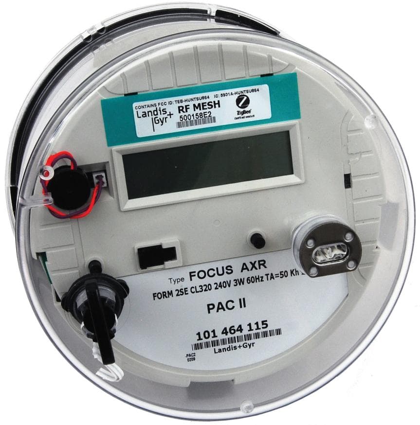
TEB-HUNTSU864
May 12, 2010FOCUS AX Modular Gridstream
Equipment Class
DTS - Digital Transmission System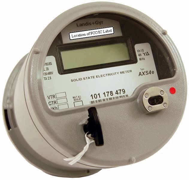
TEB-HUNTSU825
Mar 07, 20103G S4e Gridstream
Equipment Class
DTS - Digital Transmission SystemTEB-HUNTTS764
Sep 15, 2009TS2 Focus AX
Equipment Class
DTS - Digital Transmission System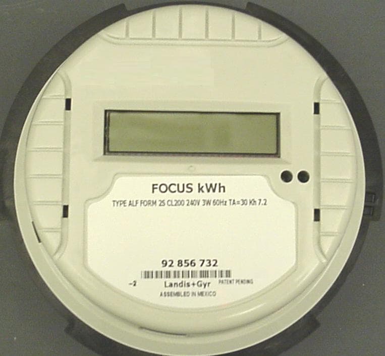
TEB-HUNTSS762
Jul 10, 2008Transmitter for Watt-Hour Meter
Equipment Class
DSS - Part 15 Spread Spectrum TransmitterTEB-HUNTSS710
May 01, 2008Multi-Utility Residential Endpoint
Equipment Class
DSS - Part 15 Spread Spectrum Transmitter