TJI-K712162.4GHz GFSK Transceiver module
Kingwave Technology Co., Ltd.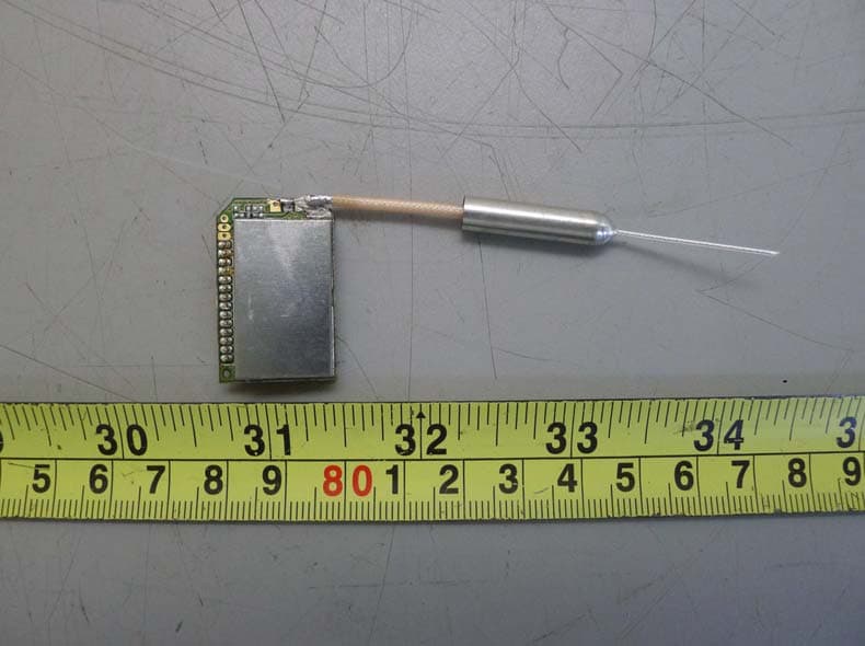
Click to zoom
Application Details
- Equipment Class
- DSS - Part 15 Spread Spectrum Transmitter
- Date of Grant
- Jul 08, 2013
- Application Purpose
- Original Equipment
- Date of Application
- Jul 08, 2013
- Equipment Note
- 2.4GHz GFSK Transceiver module
- Frequency Range
- 2408.62500000 - 2473.87500000
- Country
- Taiwan
Documents & Files
Document Text
Text extracted from the exhibit documents filed with the FCC. Open a document above to read the original.
Users Manual
- 1- K71216 2.4GHz GFSK Transceiver module Manual 1. Introduction K71216 is a 2.4GHz ISM band transceiver. It provides one type of digital modulation GFSK, and on-air data rate support 3Mbps. The proprietary low MAC feature coupled with high-speed multimedia processor enables a very high quality wireless multimedia application and a great interference immunity capability. 2. Pin Assignment 1 5 10 14 ANT PORT - 2- 3. Installation Putting the module on the carrier board with socket. 4. SPI Digital Interface All configurations of K71216 are defined by the values of register map. The register map can be accessed via SPI digital interface coupled with external MCU. All configuration values need to be properly set into four types of register maps. 5. SPI format - 3- 6. Dimension NOTICE : The changes or modifications not expressly approved by the party responsible for compliance could void the user’s authority to operate the equipment. IMPORTANT NOTE: To comply with the FCC RF exposure compliance requirements, No change to the antenna or the device is permitted. Any change to the antenna or the device could result in the device exceeding the RF exposure requirements and void user’s authority to operate the device. FCC ID Label Graph: This device complies with Part 15 of the FCC Rules. Operation is subject to the following two conditions: (1) this device may not cause harmful interference, and (2) this device must accept any interference received, including interference that may cause undesired operation. NOTE: If the product is too small to make so many text labels, only need to indicate the FCC ID number on the label, but the above text will be printed in the manual or packaging box. FCC ID : TJI-K71216 4 THIS DEVICE COMPLIES WITH PART 15 OF THE FCC RULES. OPERATION IS SUBJECT TO THE FOLLOWING TWO CONDITIONS: (1) THIS DEVICE MAY NOT CAUSE HARMFUL INTERFERENCE AND (2) THIS DEVICE MUST ACCEPT ANY INTERFERENCE RECEIVED, INCLUDING INTERFERENCE THAT MAY CAUSE UNDESIRED OPERATION. Federal Communications Commission Requirements The equipment has been tested and fo und to comply with the limits for Class B Digital Device, pursuant to part 15 of the FCC Rules. These limits are designed to provide reasonable protection against harmful interference in a residential installation. This equipment generates uses and can radiate radio frequency energy and, if not installed and used in acc ordance with the instruction, may cause harmful interference to radio communication. However, there is no guarantee that interference will not occur in a particular installation. If this equipment does cause harmful interference to radio or television reception, which can be determined by turning the equipment off and on, the user is enc ouraged to try to correct the interference by one or more of the following measures: ●Reorient of relocate the receiving antenna. ●Increase the separation between the equipment and receiver. ●Connect the equipment into an outlet on a circuit different from that to which the receiver is connected. ●Consult th e dealer or an experienced radio/TV technician for help. THE CHANGES OR MODIFICATIONS NOT EXPRESSLY APPROVED BY THE PARTY RESPONSIBLE FOR COMPLIANCE COULD VOID THE USER'S AUTHORITY TO OPERATE THE EQUIPMENT. This device complies with Part 15 of the FCC Rules. Operation is subject to the following two conditions: (1) This device ma y not cause harmful interference, and receiver. (2) This device must accept any interference received, including interference that may cause undesired operation. FCC Radiation Exposure Statement The equipment complies with FCC radiation exposure limits set forth for uncontrolled equipment and meets the FCC radio frequency (RF) Exposure Guidelines in S upplement C to OET65. The equipment has very low levels of RF energy that it is deemed to comply without testing of specific absorption ratio (SAR) Modular approval RF Exposure: This equipment must be installed and operated in accordance with provided instructions and the antenna(s) used for this transmitter mus t be installed to provide a separation distance of at least 20 cm from all persons and must not be co‐located or operating in conjunction with 5 any other antenna or transmitter. End‐users and installers must be provide with antenna installation instructions and consider removing the no‐collocation statement. End Product Labeling This transmitter module is authorized only for use in device where the antenna may be installed such that 20 cm may be maintained between the an tenna and user s. The final end product must be labeled in a visible area with the following: “Contains FCC ID:TJI‐K71216”. Manual Information To the End User The OEM integrator has to be aware not to provide information to the end user regarding how to install or remove this RF module in the user ’ s manual of the end product which integrates this module. The end user manual shall include all required regulatory information/warming as shown in this manual.
External Photos
RV-0000000 Project No.: 1305107 Page 2 of 4 Neutron Engineering Inc. 1305107 Antenna
Internal Photos
RV-0000000 Project No.: 1305107 Page 3 of 4 Neutron Engineering Inc. 1305107 1305107 RV-0000000 Project No.: 1305107 Page 4 of 4 Neutron Engineering Inc. 1305107 1305107
RF Exposure Info
RV-0000000 Report No.: NEI-FCCP-1-1305107 Page 62 of 64 Neutron Engineering Inc. 11 RF EXPOSURE COMPLIANCE 11.1 LIMIT Systems operating under the provisions of this section shall be operated in a manner that ensures that the public is not exposed to radio frequency energy levels in excess limit for maximum permissible exposure. In accordance with 47 CFR FCC Part 2 Subpart J, section 2.1091 this device has been defined as a mobile device whereby a distance of 0.2 m normally can be maintained between the user and the device. (A) Limits for Occupational / Controlled Exposure Frequency Range (MHz) Electric Field Strength (E) (V/m) Magnetic Field Strength (H) (A/m) Power Density (S) (mW/ cm 2 ) Averaging Time |E| 2 ,|H| 2 or S (minutes) 0.3-3.0 614 1.63 (100)* 6 3.0-30 1842 / f 4.89 / f (900 / f)* 6 30-300 61.4 0.163 1.0 6 300-1500 F/300 6 1500-100,000 5 6 (B) Limits for General Population / Uncontrolled Exposure Frequency Range (MHz) Electric Field Strength (E) (V/m) Magnetic Field Strength (H) (A/m) Power Density (S) (mW/ cm 2 ) Averaging Time |E| 2 ,|H| 2 or S (minutes) 0.3-1.34 614 1.63 (100)* 30 1.34-30 824/f 2.19/f (180/f)* 30 30-300 27.5 0.073 0.2 30 300-1500 F/1500 30 1500-100,000 1.0 30 NOTE: f = frequency in MHz ; *Plane-wave equivalent power density. 11.2 MEASUREMENT INSTRUMENTS LIST Item Kind of EquipmentManufacturer Type No. Serial No. Calibrated until 1 Power Meter Anritsu ML2487A 6K00004714 Feb. 26, 2014 2 Power Meter Sensor Anritsu MA2491A 34138 Feb. 26, 2014 NOTE: N/A: denotes No Model Name, No Serial No. or No Calibration specified. 11.3 MPE CALCULATION METHOD E (V/m) = d GP××30 Power Density: Pd (W/m²) = 377 2 E E = Electric field (V/m) P = Peak RF output power (W) G = EUT Antenna numeric gain (numeric) d = Separation distance between radiator and human body (m) The formula can be changed to Pd = 2 377 30 d GP × ×× From the peak EUT RF output power, the minimum mobile separation distance, d=0.2m, as well as the gain of the used antenna, the RF power density can be obtained RV-0000000 Report No.: NEI-FCCP-1-1305107 Page 63 of 64 Neutron Engineering Inc. 11.4 TEST SETUP LAYOUT 11.5 DEVIATION FROM TEST STANDARD No deviation 11.6 EUT OPERATING CONDITIONS The EUT tested system was configured as the statements of 4.6 Unless otherwise a special operating condition is specified in the follows during the testing. 11.7 TEST RESULTS The power is so low so there is no need for RF calculations.
Test Report
RV-0000000 Report No.: NEI-FCCP-1-1305107 Page 1 of 64 Neutron Engineering Inc. Radio Test Report FCC ID: TJI-K71216 This report concerns (check one) : Original Grant Class II Change Issued Date : Jun. 07, 2013 Project No. : 1305107 Equipment : 2.4GHz GFSK Transceiver module Model Name : K71216 Applicant : KINGWAVE TECHNOLOGY CO., LTD Address : 18F.-3, No.186, Jian 1st Rd., Zhonghe Dist., New Taipei City 235, Taiwan (R.O.C.) Tested by: Neutron Engineering Inc. EMC Laboratory Date of Receipt: May 10, 2013 Date of Test: May 10, 2013 ~ Jun. 05, 2013 Testing Engineer : (Josh Lin) Technical Manager : (Jeff Yang) Authorized Signatory : (Andy Chiu) Neutron Engineering Inc. B1, No. 37, Lane 365, YangGuang St., NeiHu District 114, Taipei, Taiwan. TEL: +886-2-2657-3299 FAX: +886-2-2657-3331 RV-0000000 Report No.: NEI-FCCP-1-1305107 Page 2 of 64 Neutron Engineering Inc. Declaration Neutron represents to the client that testing is done in accordance with standard procedures as applicable and that test instruments used has been calibrated with the standards traceable to National Measurement Laboratory (NML) of R.O.C., or National Institute of Standards and Technology (NIST) of U.S.A. Neutron's reports apply only to the specific samples tested under conditions. It is manufacture’s responsibility to ensure that additional production units of this model are manufactured with the identical electrical and mechanical components. Neutron shall have no liability for any declarations, inferences or generalizations drawn by the client or others from Neutron issued reports. Neutron’s reports must not be used by the client to claim product endorsement by the authorities or any agency of the Government. This report is the confidential property of the client. As a mutual protection to the clients, the public and Neutron-self, extracts from the test report shall not be reproduced except in full with Neutron’s authorized written approval. Neutron’s laboratory quality assurance procedures are in compliance with the ISO Guide 17025 requirements, and accredited by the conformity assessment authorities listed in this test report. Limitation For the use of the authority's logo is limited unless the Test Standard(s)/Scope(s)/Item(s) mentioned in this test report is (are) included in the conformity assessment authorities acceptance respective. RV-0000000 Report No.: NEI-FCCP-1-1305107 Page 3 of 64 Neutron Engineering Inc. Table of Contents REPORT ISSUED HISTORY 6 1 CERTIFICATION 7 2 . SUMMARY OF TEST RESULTS 8 2.1 TEST FACILITY 9 2.2 MEASUREMENT UNCERTAINTY 9 3 GENERAL INFORMATION 10 3.1 GENERAL DESCRIPTION OF EUT 10 3.2 DESCRIPTION OF TEST MODES 11 3.3 TABLE OF PARAMETERS OF TEXT SOFTWARE SETTING 12 3.4 BLOCK DIAGRAM SHOWING THE CONFIGURATION OF SYSTEM TESTED 13 3.5 DESCRIPTION OF SUPPORT UNITS 14 4 ANTENNA CONDUCTED SPURIOUS EMISSION 15 4.1 LIMIT 15 4.2 MEASUREMENT INSTRUMENTS LIST 15 4.3 TEST PROCEDURES 15 4.4 TEST SETUP LAYOUT 15 4.5 DEVIATION FROM TEST STANDARD 15 4.6 EUT OPERATING CONDITIONS 15 4.7 TEST RESULTS 16 5 HOPPING CHANNEL SEPARATION 20 5.1 LIMIT 20 5.2 MEASUREMENT INSTRUMENTS LIST 20 5.3 MEASURING INSTRUMENTS SETTING 20 5.4 TEST PROCEDURES 20 5.5 TEST SETUP LAYOUT 20 5.6 DEVIATION FROM TEST STANDARD 20 5.7 EUT OPERATING CONDITIONS 20 5.8 TEST RESULTS 21 6 MAXIMUM PEAK CONDUCTED OUTPUT POWER 25 6.1 LIMIT 25 6.2 MEASUREMENT INSTRUMENTS LIST 25 6.3 TEST PROCEDURES 25 6.4 TEST SETUP LAYOUT 25 6.5 DEVIATION FROM TEST STANDARD 25 6.6 EUT OPERATING CONDITIONS 25 6.7 TEST RESULTS 26 7 RADIATED SPURIOUS EMISSION (9 KHZ TO 1 GHZ) 28 7.1 LIMIT 28 RV-0000000 Report No.: NEI-FCCP-1-1305107 Page 4 of 64 Neutron Engineering Inc. Table of Contents 7.2 MEASUREMENT INSTRUMENTS LIST 29 7.3 MEASURING INSTRUMENTS SETTING 29 7.4 TEST PROCEDURES 30 7.5 DEVIATION FROM TEST STANDARD 30 7.6 TEST SETUP LAYOUT 30 7.7 EUT OPERATING CONDITIONS 31 7.8 TEST RESULTS 32 8 RADIATED SPURIOUS EMISSION (ABOVE 1 GHZ) 34 8.1 LIMIT 34 8.2 MEASUREMENT INSTRUMENTS LIST 35 8.3 MEASURING INSTRUMENTS SETTING 35 8.4 TEST PROCEDURES 36 8.5 DEVIATION FROM TEST STANDARD 36 8.6 TEST SETUP LAYOUT 36 8.7 EUT OPERATING CONDITIONS 37 8.8 TEST RESULTS 38 8.9 TEST RESULTS (RESTRICTED BANDS) 50 9 NUMBER OF HOPPING FREQUENCY 54 9.1 LIMIT 54 9.2 MEASUREMENT INSTRUMENTS LIST 54 9.3 MEASURING INSTRUMENTS SETTING 54 9.4 TEST PROCEDURES 54 9.5 TEST SETUP LAYOUT 54 9.6 DEVIATION FROM TEST STANDARD 54 9.7 EUT OPERATING CONDITIONS 54 9.8 TEST RESULTS 55 10 AVERAGE TIME OF OCCUPANCY 56 10.1 LIMIT 56 10.2 MEASUREMENT INSTRUMENTS LIST 56 10.3 TEST PROCEDURES 56 10.4 TEST SETUP LAYOUT 56 10.5 DEVIATION FROM TEST STANDARD 56 10.6 EUT OPERATING CONDITIONS 57 10.7 TEST RESULTS 58 11 RF EXPOSURE COMPLIANCE 62 11.1 LIMIT 62 11.2 MEASUREMENT INSTRUMENTS LIST 62 11.3 MPE CALCULATION METHOD 62 RV-0000000 Report No.: NEI-FCCP-1-1305107 Page 5 of 64 Neutron Engineering Inc. Table of Contents 11.4 TEST SETUP LAYOUT 63 11.5 DEVIATION FROM TEST STANDARD 63 11.6 EUT OPERATING CONDITIONS 63 11.7 TEST RESULTS 63 12 EUT TEST PHOTO 64 RV-0000000 Report No.: NEI-FCCP-1-1305107 Page 6 of 64 Neutron Engineering Inc. REPORT ISSUED HISTORY Revised Version No. Description Issued Date - Initial Issue. Jun. 07, 2013 RV-0000000 Report No.: NEI-FCCP-1-1305107 Page 7 of 64 Neutron Engineering Inc. 1 CERTIFICATION E q u i p m e n t : 2.4GHz GFSK Transceiver module Brand Name : KINGWAVE Model Name : K71216 A p p l i c a n t : KINGWAVE TECHNOLOGY CO., LTD Date of Test : May 10, 2013 ~ Jun. 05, 2013 Standards : FCC Part 15, Subpart C: 2012 ANSI C63.4: 2009 The above equipment has been tested and found compliance with the requirement of the relative standards by Neutron Engineering Inc. EMC Laboratory. The test data, data evaluation, and equipment configuration contained in our test report (Ref No. NEI-FCCP-1-1305107) were obtained utilizing the test procedures, test instruments, test sites that has been accredited by the Authority of TAF according to the ISO-17025 quality assessment standard and technical sta…
Text truncated - open the document above for the full version.
Test Setup Photos
RV-0000000 Report No.: NEI-FCCP-1-1305107 Page 64 of 64 Neutron Engineering Inc. 12 EUT TEST PHOTO Radiated spurious emission test photos 1305107 1305107
Contact Information
Applicant
Ming-Shan Chan(Engineer)
Technical Contact
Neutron Engineering Inc.Kate Lin
886-2-2657-3299
Taiwan
Non-Technical Contact
Neutron Engineering Inc.Kate Lin
[email protected]886-2-2657-3299
Test Firm
BTL Inc.Andy Chiu
Technical Specifications
| # | Rule Parts | Frequency Range | Power Output |
|---|---|---|---|
| 1 | 15C | 2.41 GHz - 2.47 GHz | 3.00 mW |
Other Applications from Kingwave Technology Co., Ltd.
TJI-K71216P
Jul 16, 20132.4GHz GFSK Transceiver module
Equipment Class
DSS - Part 15 Spread Spectrum Transmitter
TJI-KWS7S3
May 23, 20122.4GHz RF Module
Equipment Class
DSS - Part 15 Spread Spectrum Transmitter
TJI-KW2431
Apr 29, 20122.4GHz Digital Wireless cameras
Equipment Class
DSS - Part 15 Spread Spectrum Transmitter
TJI-KW2430SA
Apr 29, 20122.4GHz Digital Transmission System
Equipment Class
DSS - Part 15 Spread Spectrum Transmitter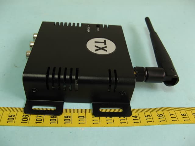
TJI-KW2425R
Aug 27, 20112.4GHz AV Sender
Equipment Class
DSS - Part 15 Spread Spectrum Transmitter