TJI-KWS7S32.4GHz RF Module
Kingwave Technology Co., Ltd.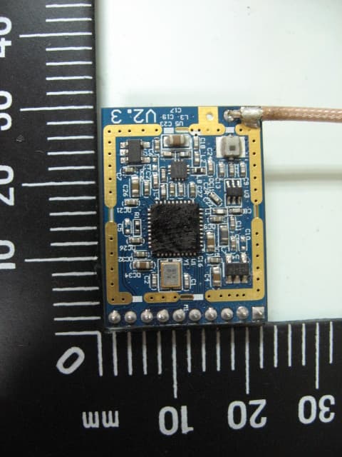
Click to zoom
Application Details
- Equipment Class
- DSS - Part 15 Spread Spectrum Transmitter
- Date of Grant
- May 23, 2012
- Application Purpose
- Original Equipment
- Date of Application
- May 23, 2012
- Equipment Note
- 2.4GHz RF Module
- Frequency Range
- 2403.00000000 - 2478.00000000
- Country
- Taiwan
Documents & Files
Document Text
Text extracted from the exhibit documents filed with the FCC. Open a document above to read the original.
Users Manual
- 1- KWS7S3 2.4GHz RF Module User Manual 1. Introduction KWS7S3 is a 2.4GHz ISM band HDR (high data rate) FH (frequency hopping) transceiver. It provides three types of digital modulation 16QAM/QPSK/BPSK, and on-air data rate support 12Mbps. The proprietary low MAC feature coupled with high-speed multimedia processor enables a very high quality wireless multimedia application and a great interference immunity capability. 2. Pin Assignment Pin 1 2 3 4 5 6 7 8 9 10 5V GND CLK OUT IRQ CS SDO SDI SCK TN CLK IN 3. Installation 1: Soldering antenna on the KWS7S3 PCB. 1 5 10 - 2- 2: Putting the module on the carrier board with socket. 4. SPI Digital Interface All configurations of KWS7S3 are defined by the values of register map. The register map can be accessed via SPI digital interface coupled with external MCU. All configuration values need to be properly set into four types of register maps. The four types of register map are defined as, PMU registers, RF registers, BB registers and MAC registers. Address setting and data access of PMU registers are defined in MAC register 0X32H to 0x33H. RF registers are defined in 0X22H to 0X24H, and BB registers are defined in 0X0EH to 0x10H. 5. SPI format SPI read operation SPI write operation 1 - 3- 6. Coaxial Cable Specification 7. IMPORTANT NOTE: To comply with the FCC RF exposure compliance requirements, the antenna(s) used for this transmitter must be installed to provide a separation distance of at least 20 cm from all persons and must not be co-located or operating in conjunction with any other antenna or transmitter. No change to the antenna or the device is permitted. Any change to the antenna or the device could result in the device exceeding the RF exposure requirements and void user’s authority to operate the device. Notice : The changes or modifications not expressly approved by the party responsible for compliance could void the user’s authority to operate the equipment. This device complies with Part 15 of the FCC Rules. Operation is subject to the following two conditions: (1) this device may not cause harmful interference, and (2) this device must accept any interference received, including interference that may cause undesired operation. Characteristics Frequency DC ~ 6GHz Impedance 50 Ohm S.W.R <=2.0 Insertion Loss <-1.5 dB Connector for reverse SMA of the Antenna Unit: mm - 4- To OEM installer: 1. FCC ID label on the final system must be labeled with "Contains FCC ID: TJI-KWS7S3" or "Contain transmitter module FCC ID: TJI-KWS7S3 ". 2. In the user manual, final system integrator must be ensured that there is no instruction provided in the user manual to install or remove the transmitter module. 3. Transmitter module must be installed and used in strict accordance with the manufacturer is instructions as described in the user documentation that comes with the product. This device complies with the following radio frequency and safety standards. USA: FCC Part 15C The user manual of the final host system must contain the following statements: USA-Federal Communication Commission (FCC) This equipment has been tested and found to comply with the limits for a Class B Digital Device, pursuant to part 15 of the FCC Rules. These limits are designed to provide reasonable protection against harmful interference in a residential installation. This equipment generates, uses and can radiate radio frequency energy and, if not installed and used in accordance with the instruction, may cause harmful interference to radio communication. However, there is no grantee that interference will not occur in a particular installation. If this equipment dose cause harmful interference to radio or television reception, which can be determined by turning the equipment off and on, the user is encouraged to try to correct the interference by one or more of the following measures: --Reorient or relocate the receiving antenna. --Increase the separation between the equipment and receiver. --Connect the equipment into an outlet on a circuit different from that to which the receiver is connected. --Consult the dealer or an experienced radio/TV technician for help. This device complies with Part 15 of the FCC Rules. Operation is subject to the following two conditions: (1) this device may not cause harmful interference, and (2) this device must accept any interference received, including interference that may cause undesired operation. The changes or modifications not expressly approved by the party responsible for compliance could void the user’s authority to operate the equipment. To comply with the FCC RF exposure compliance requirements, the antenna(s) used for this transmitter must be installed to provide a separation distance of at least 20 cm from all persons and must not be co-located or operating in conjunction with any other antenna or transmitter. No change to the antenna or the device is permitted. Any change to the antenna or the device could result in the device exceeding the RF exposure requirements and void user’s authority to operate the device.
Cover Letter(s)
Applicant/Grantee KINGWAVE TECHNOLOGY CO., LTD FCC ID: TJI-KWS7S3 Section 15.212 Modular Transmitters Request for Modular Approval Request for Limited Modular Approval Requirements EUT Conditions Comply (Y/N) Single Modular Approval Requirements 1 The radio elements of the modular transmitter must have their own shielding. The physical crystal and tuning capacitors may be located external to the shielded radio elements. Device is equipped with Metal shielding to cover RF section. Refer to external photos. Y 2 The modular transmitter must have buffered modulation/data inputs (if such inputs are provided) to ensure that the module will comply with Part 15 requirements under conditions of excessive data rates or over-modulation. All inputs to the modules are buffered through logic or microprocessor inputs. Y 3 The modular transmitter must have its own power supply regulation. Internal 3.3V power regulator. Refer to Block diagram and Technical description file. Y 4 The modular transmitter must comply with the antenna and transmission system requirements of Sections 15.203, 15.204(b) and 15.204(c). The antenna must either be permanently attached or employ a “unique” antenna coupler (at all connections between the module and the antenna, including the cable). The “professional installation” provision of Section 15.203 is not applicable to modules but can apply to limited modular approvals under paragraph (b) of this section. Device is equipped with unique antenna connector. Refer to external photos. Y 5 The modular transmitter must be tested in a stand-alone configuration, i.e., the module must not be inside another device during testing for compliance with Part 15 requirements. Unless the transmitter module will be battery powered, it must comply with the AC line conducted requirements found in Section 15.207. AC or DC power lines and data input/output lines connected to the module must not contain ferrites, unless they will be marketed with the module (see Section 15.27(a)). The length of these lines shall be the length typical of actual use or, if that length is unknown, at least 10 centimeters to insure that there is no coupling between Device was tested outside the host computer as stand-alone configuration. Refer to setup photos. Y the case of the module and supporting equipment. Any accessories, peripherals, or support equipment connected to the module during testing shall be unmodified and commercially available (see Section 15.31(i)). 6 The modular transmitter must be equipped with either a permanently affixed label or must be capable of electronically displaying its FCC identification number. (A) If using a permanently affixed label, the modular transmitter must be labeled with its own FCC identification number, and, if the FCC identification number is not visible when the module is installed inside another device, then the outside of the device into which the module is installed must also display a label referring to the enclosed module. This exterior label can use wording such as the following: “Contains Transmitter Module FCC ID: XYZMODEL1” or “Contains FCC ID: XYZMODEL1.” Any similar wording that expresses the same meaning may be used. The Grantee may either provide such a label, an example of which must be included in the application for equipment authorization, or, must provide adequate instructions along with the module which explain this requirement. In the latter case, a copy of these instructions must be included in the application for equipment authorization. (B) If the modular transmitter uses an electronic display of the FCC identification number, the information must be readily accessible and visible on the modular transmitter or on the device in which it is installed. If the module is installed inside another device, then the outside of the device into which the module is installed must display a label referring to the enclosed module. This exterior label can use wording such as the following: “Contains FCC certified transmitter module(s).” Any similar wording that expresses the same meaning may be used. The user manual must include instructions on how to access the electronic display. A copy of these instructions must be included in the application for equipment authorization. Two proposed FCC ID label format are included in the filing. One of label is to be placed on the module and the other label is to be placed on the outside of system. Refer to FCC ID label format and location file. Y 7 The modular transmitter must comply with any specific rules or operating requirements that ordinarily apply to a complete transmitter and the manufacturer must provide adequate instructions along with the module to explain any such requirements. A copy of these instructions must be included in the Transmitter module will only be installed by Kingwave and Lb Sender or Kingwave’s authorized OEM installer. This device will not be sold as module transmitter. Y application for equipment authorization. 8 The modular transmitter must comply with any applicable RF exposure requirements in its final configuration. The max. output power measured is 16.74 dBm. This device will be installed in Kingwave and Lb Sender. Y A limited modular approval may be granted for single or split modular transmitters that do not comply with all of the above requirements, e.g., shielding, minimum signaling amplitude, buffered modulation/data inputs, or power supply regulation, if the manufacturer can demonstrate by alternative means in the application for equipment authorization that the modular transmitter meets all the applicable Part 15 requirements under the operating conditions in which the transmitter will be used. Limited modular approval also may be granted in those instances where compliance with RF exposure rules is demonstrated only for particular product configurations. The applicant for certification must state how control of the end product into which the module will be installed will be maintaine…
Text truncated - open the document above for the full version.
External Photos
ETC Report No. : 12-04-RBF-190-01 FCC ID.: TJI-KWS7S3 Sheet 1 of 3 Sheets Rev. No 2.1 CONSTRUCTED PHOTOS of EUT 1. The RF module 2. ETC Report No. : 12-04-RBF-190-01 FCC ID.: TJI-KWS7S3 Sheet 2 of 3 Sheets Rev. No 2.1 CONSTRUCTED PHOTOS of EUT 3. ETC Report No. : 12-04-RBF-190-01 FCC ID.: TJI-KWS7S3 Sheet 3 of 3 Sheets Rev. No 2.1 CONSTRUCTED PHOTOS of EUT 4. 5.
ID Label/Location Info
If using a permanently affixed label, the modular transmitter must be labeled with its own FCC identification number, and, if the FCC identification number is not visible when the module is installed inside another device, then the outside of the device into which the module is installed must also display a label referring to the enclosed module. This exterior label can use wording such as the following: “Contains FCC ID: TJI‐KWS7S3”. Example of the exterior label: Yo u r t rad e name or logo Model: XXXXXX Contains FCC ID: TJI‐KWS7S3
ID Label/Location Info
23mm * 15mm
Internal Photos
ETC Report No. : 12-04-RBF-190-01 FCC ID.: TJI-KWS7S3 Sheet 3 of 3 Sheets Rev. No 2.1 CONSTRUCTED PHOTOS of EUT 4. 5.
Parts List/Tune Up Info
承 認 書 SPECIFICATION FOR APPROVAL 客 戶 CUSTOMER 日 期 DATE 品 名 DESCRIPTION 客 戶 料 號 CUSTOMER P/N 成 品 編 號 Part NO. 萬旭電業股份有限公司 WANSHIH ELECTRONIC CO., LTD. 台北縣五股鄉五工六路72號3樓 3F 72 WU KONG 6TH RD., WU KU INDUSTRIAL DISTRICT TAIPEI HSIEN, TAIWAN,R.O.C. TEL:(02) 22988066 (5 LINE) FAX:(02)22981102 2012/3/22 2.4GHz High Gain Patch Antenna with RP-SMA(M)(Black) 1 Table of Contents Table of Contents ......... 1 Specification ......... 2 Antenna Drawing ......... 3 Electrical Properties Return Loss ......... 4 V. S . W. R ......... 4 Radiation Pattern ......... 5 2 SPECIFICATION 1. Description :2.4GHz Patch Antenna 2. Customer : 3. Part No. : 4. Standard :IEEE 802.11b/g Wireless LAN 5. Antenna Profile :125*79.5*14.1 mm 6. Color :Black 7. Electrical Characteristics Operating Frequency :2.4~2.5GHz Antenna Type :Patch Polarization Type :Linear Type of Radiation :Directional Antenna Gain :High Gain Impedance :50 Ohm nominal V.S.W.R. :2.0:1 Max. 8. Mechanical Characteristics Swivel :90 degrees Connector :RP-SMA(M) 9. Raw Material Coaxial Cable :RG-178 3 Jason 劉建勝郭雅珍 Jakcy 3 2.4GHz High Gain Patch Antenna with RP-SMA(M)(Black) 3 RP-SMA(M) 母PIN 塑件:黑色 4 Electrical Properties Return Loss Electrical Properties V. S . W. R 5 Electrical Properties Radiation Pattern – H Plane Electrical Properties Radiation Pattern – E Plane
Parts List/Tune Up Info
Product Number: AN2400-5901RS Product Name: 2.4 GHz Antenna Page 1 Version: 3.0 Issue Date: 2009-04-08 Index: 1. Reliability Testing 2. Specification 3. S Parameter Test Data 4. Antenna Radiation Pattern 5. Mechanical Drawing 6. MSDS & SGS Report ================================================== 1. Reliability Testing Test Item Procedure Requirement 1. Visual inspection and Dimension Check Applicable methods using x5 magnification follow specification 2. Rapid Changing of Temperature -40 ̊C (30minutes) to 90 ̊C (30minutes); 24 cycles After 2 hours recovery: 1. no visible damage 2. Freq. Tol.: < ±5% 3. Damp Heat 24 hours at 60 ̊C; 90 ~ 95% RH After 2 hours recovery: 1. no visible damage 2. Freq. Tol. : < ±5% 4. Endurance 24 hours at 90 ̊C After 2 hours recovery: 1. no visible damage 2. Freq Tol.: < ±5% 5. Connector Rotation Force 1200 - 1600 g.cm 1. no visible damage 2. Freq Tol.: < ±5% 6. Connector Pull Force >= 5.0 Kg 1. no visible damage 2. Freq Tol.: < ±5% Product Number: AN2400-5901RS Product Name: 2.4 GHz Antenna Page 2 Version: 3.0 Issue Date: 2009-04-08 2. Specification A. Electrical Characteristics Return Loss (dB) <= 2.0 @ 2400 - 2500 MHz Antenna Gain 9 ± 0.7 dBi @ 2450 MHz Radiation Pattern 360 Degree / Omni-Directional Impedance 50 Ohm B. Material Material of Plastic ABS / PA-6 Material of Metal Cu(Plated) Connector SMA Male Reverse C. Environmental Operation Temperature - 30 ̊C ~ + 85 ̊C Storage Temperature - 30 ̊C ~ + 85 ̊C 3. S Parameter Test Data Product Number: AN2400-5901RS Product Name: 2.4 GHz Antenna Page 3 Version: 3.0 Issue Date: 2009-04-08 4. Antenna Radiation Pattern Testing Equipment Specification: Antenna Anechoic Chamber Dimension: 8 x 4 x 4 m Quite Zone: 600mm @1 GHz Isolation: >100dB @ 1 MHz ~ 10 GHz Testing Equipment: Agilent 5071B Received Antenna: 0.7 ~ 6.0 GHz for Gain Calibration Double Ridged Horn Antenna 5. Mechanical Drawing 6. MSDS & SGS Report Electrical Performance-Radiation Pattern and Gain H-Plane 2400MHz 2450MHz 2500MHz 0 45 90 135 180 225 270 315 0 0 -10 -10 -20 -20 -30 -30 -40 -40 Unit: dBi 8.1 Tol. Gain (avg.)= 9.0 Tol. Gain (max.)= -13.8 Hor. Pol. (avg.)= -7.9 Hor. Pol. (max.)= 8.1 Ver. Pol. (avg.)= 9.0 Ver. Pol. (max.)= 0 45 90 135 180 225 270 315 0 0 -10 -10 -20 -20 -30 -30 -40 -40 Unit: dBi 7.6 Tol. Gain (avg.)= 8.7 Tol. Gain (max.)= -14.1 Hor. Pol. (avg.)= -8.6 Hor. Pol. (max.)= 7.6 Ver. Pol. (avg.)= 8.7 Ver. Pol. (max.)= Unit: dBi 7.0 Tol. Gain (avg.)= 8.7 Tol. Gain (max.)= -14.3 Hor. Pol. (avg.)= -8.5 Hor. Pol. (max.)= 7.0 Ver. Pol. (avg.)= 8.7 Ver. Pol. (max.)= 0 45 90 135 180 225 270 315 0 0 -10 -10 -20 -20 -30 -30 -40 -40 Electrical Performance-Radiation Pattern and Gain E-Plane 2400MHz 2450MHz 2500MHz 0 45 90 135 180 225 270 315 0 0 -10 -10 -20 -20 -30 -30 -40 -40 Unit: dBi 0.0 Tol. Gain (avg.)= 9.3 Tol. Gain (max.)= -0.1 Hor. Pol. (avg.)= 9.3 Hor. Pol. (max.)= -15.6 Ver. Pol. (avg.)= -9.6 Ver. Pol. (max.)= 0 45 90 135 180 225 270 315 0 0 -10 -10 -20 -20 -30 -30 -40 -40 Unit: dBi -0.3 Tol. Gain (avg.)= 8.9 Tol. Gain (max.)= -0.3 Hor. Pol. (avg.)= 8.9 Hor. Pol. (max.)= -16.4 Ver. Pol. (avg.)= -10.1 Ver. Pol. (max.)= 0 45 90 135 180 225 270 315 0 0 -10 -10 -20 -20 -30 -30 -40 -40 Unit: dBi -0.9 Tol. Gain (avg.)= 8.5 Tol. Gain (max.)= -0.9 Hor. Pol. (avg.)= 8.5 Hor. Pol. (max.)= -16.2 Ver. Pol. (avg.)= -11.3 Ver. Pol. (max.)=
Parts List/Tune Up Info
承 認 書 SPECIFICATION FOR APPROVAL 客 戶 CUSTOMER 日 期 DATE 品 名 DESCRIPTION 客 戶 料 號 CUSTOMER P/N 成 品 編 號 Part NO. 萬旭電業股份有限公司 WANSHIH ELECTRONIC CO., LTD. 台北縣五股鄉五工六路72號3樓 3F 72 WU KONG 6TH RD., WU KU INDUSTRIAL DISTRICT TAIPEI HSIEN, TAIWAN,R.O.C. TEL:(02) 22988066 (5 LINE) FAX:(02)22981102 晶暉科技股份有限公司 2007/12/13 YXW1016A1 WSS001 Dual Band Dipole Antenna with RP-SMA(M)(Black) A2-WSS001-F 5.8G 1 Table of Contents Table of Contents ......... 1 Specification ......... 2 Antenna Drawing ......... 3 Electrical Properties Return Loss ......... 4 V. S . W. R ......... 5 Radiation Pattern ......... 6-7 Material Data Sheet Connector/Sleeve/Rivet ......... 8-28 Coaxial Cable ......... 29-36 Housing ......... 37-43 Hinge ......... 44-49 Heat Shrink Tube ......... 50-54 2 SPECIFICATION 1. Description :WSS001 Dual Band Dipole Antenna 2. Customer :晶暉科技股份有限公司 3. Model No. :WSS001 4. Part No. :YXW1016A1 5. Standard :IEEE 802.11a/b/g Wireless LAN 6. Antenna Profile :137.5 mm (see Drawing) 7. Color :Black 8. Electrical Characteristics Operating Frequency :2.4~2.5 & 5.15~5.35 & 5.725~5.85GHz Antenna Type :Dipole Polarization Type :Linear Type of Radiation :Toroidal Peak Gain :2.0 dBi Typical Impedance :50 Ohm nominal V.S.W.R. :2.0:1 Max. 9. Mechanical Characteristics Connector :RP-SMA(M) Core :N/A 10. Raw Material Coaxial Cable :RG-178 Housing :TPU Hinge :PC+ALLOY 3 X ±1.0 X.X ±0.5 X.XX ±0.2 ANGULAR ±5.0° TOLERANCES: 郭雅珍郭慧純Jason YXW1016 WSS001 Dual Band Dipole Antenna with RP-SMA(M)(Black) 作業注意: 1. 天線本體,WSW0028A、WSW0055A 天線作業標準指導書規定製作。 依據 AQ-0028A、AQ-0055A QC管理工程圖 ,執行品質管制。 銅管 銅管 A2-WSS001-F 5.8G 環材 10外套 L96<黑>ν B2WSS001L096IT @WSS001 13φ*96L 外套<黑>黑1 或同級品 9熱縮套管ν 53A405002000BC @F34 5.0 黑 L=20mm黑1 或同級品 8銅管 24Lν B248L2400000A5 @4.8φ*24L 銅管<平頭>銀1 或同級品 7銅管 22Lν B252L2200000A5 @5.2φ*22L FOR 178 銅管<平頭>銀1 或同級品 6固定鉚釘(黑鋅)ν B02892200160A5 @028922001-6 4.80*1.95φ固定鉚釘<大>(黑鋅)黑2 或同級品 5下座<黑>ν B130L02550001I @13φ下座 * 25.5L <黑> 黑1 或同級品 4上座<黑>ν B130L02800001I @13φ上座 *28L 孔15.2*7.25 <黑> 黑1 或同級品 3 RP-SMA φ12.5 連接軸 ν B0249AB00000A5 @0249A-B Connector RP-SMA(M) φ12.5 銀銀1 或同級品 2 RP-SMA φ12.5 本體 ν B0249AA00000A5 @0249A-A Body RP-SMA(M) φ12.5 Connector 黑黑1 或同級品 1 RG-178 Coaxial Cable ν 19RG17800030AE @RG-178 CABLE 105SV(萬泰)橙 54 1或同級品 NO材料名稱環材 電腦編號零件規格顏色 切斷尺寸 用量 備註 4 Electrical Properties Return Loss 5 Electrical Properties V. S . W. R 6 Electrical Properties Radiation Pattern – H Plane 7 Electrical Properties Radiation Pattern – E Plane 8 Material Data Sheet Connector/Sleeve/Rivet 9 10 11 12 13 14 15 16 17 18 19 20 21 22 23 24 25 26 27 28 29 Material Data Sheet RG-178 Coaxial Cable 30 31 32 33 34 35 36 37 Housing Material Data Sheet z Housing(外套)- TPU 38 39 40 41 42 43 44 z Hinge(上座/下座)- PC +ALLOY 45 46 47 48 49
RF Exposure Info
FCC ID: TJI-KWS7S3 RF Exposure Evaluation of E.U.T. : 2.4GHz RF Module FCC ID. : KWS7S3 MODEL : TJI-KWS7S3 for APPLICANT : KINGWAVE TECHNOLOGY CO., LTD ADDRESS : 8F-3, No. 186, Jian-Yi Road, Chung-Ho City, 235, Taipei, Taiwan Prepared by ELECTRONICS TESTING CENTER, TAIWAN NO. 34. LIN 5. DINGFU, LINKOU DIST., NEW TAIPEI CITY, TAIWAN, 24442, R.O.C. Tel:(02)26023052 Fax:(02)26010910 http://www.etc.org.tw ; e-mail: [email protected] Report Number : 12-04-RBF-190-01-MPE FCC ID: TJI-KWS7S3 Product Information: Type of EUT: 2.4GHz RF Module FCC ID: TJI-KWS7S3 Manufacturer: KINGWAVE TECHNOLOGY CO., LTD Model: KWS7S3 Description: MODULATION TYPE CCK, DQPSK, DBPSK for DSSS 64QAM, 16QAM, QPSK, BPSK for OFDM MODULATION TECHNOLOGY DSSS, OFDM TRANSFER RATE 802.11b: 11 / 5.5 / 2 / 1Mbps 802.11g: 54 / 48 / 36 / 24 / 18 / 12 / 9 / 6Mbps Draft 802.11n (20MHz) (800ns GI): 130 / 117 / 104 / 78 / 65 / 58.5 / 52 / 39 / 26 / 19.5 / 13 / 6.5Mbps. Draft 802.11n (40MHz) (400ns GI): 270 / 243 / 216 / 162 / 135 / 121.5 / 108 / 81 / 54 / 40.5 / 27 / 13.5Mbps. FREQUENCY RANGE 802.11b & 802.11g: 2412 ~ 2462MHz NUMBER OF CHANNEL 11 for 802.11b, 802.11g, draft 802.11n (20MHz) 7 for draft 802.11n (40MHz) Maximum conducted output power (measured): 16.74 dBm or 47.206mW The following table lists the provided authorized antennas: Antenna Gain Model Antenna Type (dBi) Numeric AN2400-5901RS 2.4 GHz AntennaDiplole 9.0 7.94 WSS006 2.4GHz Antenna Diplole 3.0 2.00 WSS001 Dual Band Dipole AntennaPatch 2.0 1.58 2.4GHz High Gain Patch Antenna Diplole 6.0 3.98 Below is an example of the RF Exposure Statement: IMPORTANT NOTE: To comply with the FCC RF exposure compliance requirements, the antenna(s) used for this transmitter must be installed to provide a separation distance of at least 20 cm from all persons and must not be co-located or operating in conjunction with any other antenna or transmitter. No change to the antenna or the device is permitted. Any change to the antenna or the device could result in the device exceeding the RF exposure requirements and void user’s authority to operate the device. FCC ID: TJI-KWS7S3 Relative Requirement for Compliance According to section 1.1310 of FCC 47 CFR Part 1, limits for maximum permissible exposure (MPE) are as following: TABLE 1 – LIMITS FOR MAXIMUN PERMISSIBLE EXPOSURE (MPE) Frequency Range (MHz) Electric Field Strength (V/m) Magnetic Field Strength (A/m) Power Density (mW/cm 2 ) Averaging Time (minutes) (A) Limits for Occupational/Controlled Exposures 0.3-3.0 .................. 6141.63*(100) 6 3-30 ..................... 1842/f4.89/f *(900/f 2 ) 6 30-300 .................. 61.40.1631.0 6 300-1500 ............... ...................... ......................f/300 6 1500-100,000 ......... ...................... ......................5 6 (B) Limits for General Population/Uncontrolled Exposure 0.3-1.34 ............... 6141.63*(100) 30 1.34-30 ............... 824/f2.19/f*(180/f2) 30 30-300 .................. 27.50.0730.2 30 300-1500 ............... ...................... ......................f/1500 30 1500-100,000 ......... ...................... ......................1.0 30 f = frequency in MHz * = Plane-wave equivalent power density NOTE 1 TO TABLE 1: Occupational/controlled limits apply in situations in which persons are exposed as a consequence of their employment provided those persons are fully aware of the potential for exposure and can exercise control over their exposure. Limits for occupational/controlled exposure also apply in situations when an individual is transient through a location where occupational / controlled limits apply provided he or she is made aware of the potential for exposure. NOTE 2 TO TABLE 1: General population/uncontrolled exposures apply in situations in which the general public may be exposed, or in which persons that are exposed as a consequence of their employment may not be fully aware of the potential for exposure or can not exercise control over their exposure. FCC ID: TJI-KWS7S3 RF Exposure Calculations: The following information provides the minimum separation distance for the highest gain antenna provided. This calculation is based on the highest EIRP possible from the system, considering maximum power and antenna gain, and considering a 1.0 mW/cm 2 uncontrolled exposure limit. The formula shown in OET Bulletin 65 is used in the calculation. Equation from page 19 of OET Bulletin 65, Edition 97-01 is: S= PG / 4πR 2 where: S = power density (in appropriate units, e.g. mW/cm 2 ) P = power input to the antenna (in appropriate units, e.g., mW) G = power gain of the antenna in the direction of interest relative to an isotropic radiator R = distance to the center of radiation of the antenna (appropriate units, e.g., cm) hence R= (PG / 4πS) 1/2 For our device P = 47.206mW G = 7.94 R = 20 cm S = (47.206 * 7.94) / (4*π*20 2 ) = 0.075 mW/cm 2 < 1.0 mW/cm 2 For complying the FCC limits for general population/uncontrolled exposure, the power density limit is 1.0 mW/cm 2 . The calculation result of the power density at a distance of 20 cm of our device is less than the limit. This means that according to OET Bulletin 65 (Edition 97-01), Supplement C (Edition 01-01), the equipment fulfills the requirements on power density for general population/uncontrolled exposure and therefore fulfills the requirements of 47 CFR Part 15.247 (b)(5).
Test Report
Rev. No 1.0 FCC Part 15 EMI TEST REPORT of E.U.T. : 2.4GHz RF Module Model : KWS7S3 FCC ID : TJI-KWS7S3 for APPLICANT : KINGWAVE TECHNOLOGY CO., LTD ADDRESS : 18F-3, No. 186, Jian-Yi Road, Chung-Ho City, 235, Taipei, Taiwan Test Performed by ELECTRONICS TESTING CENTER, TAIWAN NO. 34. LIN 5. DINGFU, LINKOU DIST., NEW TAIPEI CITY, TAIWAN, 24442, R.O.C. Tel:(02)26023052 Fax:(02)26010910 http://www.etc.org.tw ; e-mail : [email protected] Report Number : 12-04-RBF-190-01 ETC Report No. : 12-04-RBF-190-01 FCC ID.:TJI-KWS7S3 Rev. No 1.0 TEST REPORT CERTIFICATION Applicant : KINGWAVE TECHNOLOGY CO., LTD 18F-3, No. 186, Jian-Yi Road, Chung-Ho City, 235, Taipei, Taiwan Manufacture : KINGWAVE TECHNOLOGY CO., LTD 18F-3, No. 186, Jian-Yi Road, Chung-Ho City, 235, Taipei, Taiwan LB TECHNOLOGY CO., LTD No.5 of Xiaoyang Rd, First Industrial Park, Tanzhou Town, Zhongshan City, Guangdong, China Description of Device : a) Type of EUT : 2.4GHz RF Module b) Trade Name : KINGWAVE c) Model No. : KWS7S3 d) Power Supply : DC 5V Regulation Applied : FCC Rules and Regulations Part 15 Subpart C I HEREBY CERTIFY THAT: The data shown in this report were made in accordance with the procedures given in ANSI C63.4, and the energy emitted by the device was founded to be within the limits applicable. I assume full responsibility for accuracy and completeness of these data. Note: 1. The result of the testing report relate only to the item tested. 2. The testing report shall not be reproduced expect in full, without the written approval of ETC. Summary of Tests Test Results Radiated Emission Pass Conducted Emission Pass Hopping Channel Separation Pass Number of Hopping frequencies used Pass Hopping Channel Bandwidth Pass Dwell Time of each frequency Pass Output Power Requirement Pass 100 kHz Bandwidth of Frequency Band Edges Requirement Pass Out-of-Band Conducted Emission Requirement Pass ETC Report No. : 12-04-RBF-190-01 FCC ID.:TJI-KWS7S3 Rev. No 1.0 Date Test Item Received : Apr 30, 2012 Date Test Campaign Completed : May 11, 2012 Date of Issue : May. 17, 2012 Test Engineer : ( Vincent Chang, Engineer ) Approve & Authorized Signer : S. S. Liou, Section Manager EMC Dept. II of ELECTRONICS TESTING CENTER, TAIWAN ETC Report No. : 12-04-RBF-190-01 FCC ID.:TJI-KWS7S3 Rev. No 1.0 Table of Contents Page 1 GENERAL INFORMATION ....................................................................................................... 1 1.1 Product Description...................................................................................................................... 1 1.2 Test Methodology ........................................................................................................................ 1 1.3 Test Facility.................................................................................................................................. 1 2 PROVISIONS APPLICABLE...................................................................................................... 2 2.1 Definition ..................................................................................................................................... 2 2.2 Requirement for Compliance ....................................................................................................... 3 2.3 Restricted Bands of Operation ..................................................................................................... 5 2.4 Labeling Requirement .................................................................................................................. 6 2.5 User Information .......................................................................................................................... 6 3 SYSTEM TEST CONFIGURATION .......................................................................................... 7 3.1 Justification .................................................................................................................................. 7 3.2 Devices for Tested System........................................................................................................... 7 4 RADIATED EMISSION MEASUREMENT .............................................................................. 8 4.1 Applicable Standard ..................................................................................................................... 8 4.2 Measurement Procedure............................................................................................................... 8 4.3 Measuring Instrument ................................................................................................................ 10 4.4 Radiated Emission Data ............................................................................................................. 11 4.5 Field Strength Calculation.......................................................................................................... 20 4.6 Photos of Radiation Measuring Setup........................................................................................ 21 5 CONDUCTED EMISSION MEASUREMENT ......................................................................…
Text truncated - open the document above for the full version.
Contact Information
Applicant
Ming-Shan Chan(Engineer)
Test Firm
Electronics Testing Center, TaiwanWill Yauo
Technical Specifications
| # | Rule Parts | Frequency Range | Power Output |
|---|---|---|---|
| 1 | 15C | 2.40 GHz - 2.48 GHz | 47.00 mW |
Other Applications from Kingwave Technology Co., Ltd.
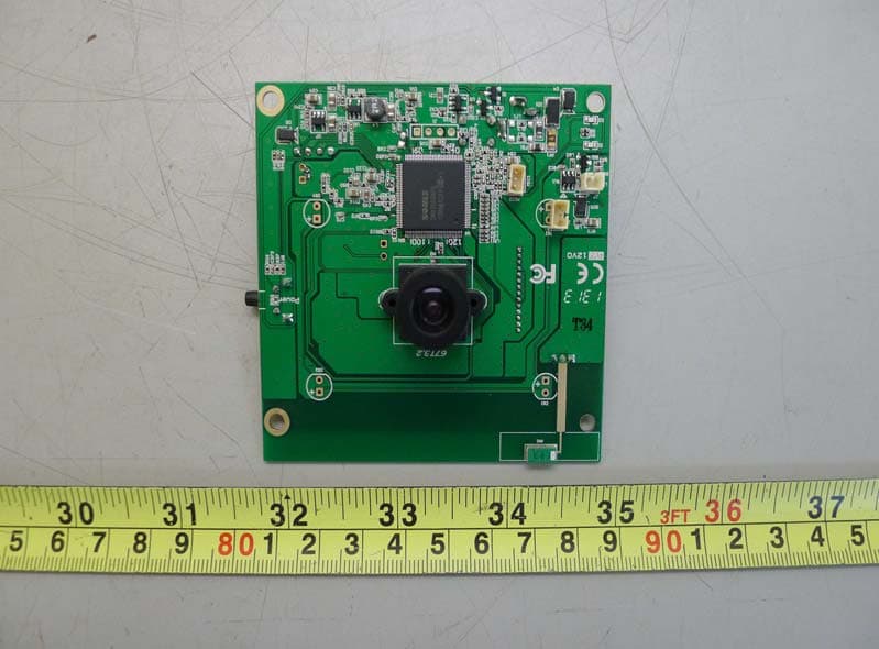
TJI-K71216P
Jul 16, 20132.4GHz GFSK Transceiver module
Equipment Class
DSS - Part 15 Spread Spectrum Transmitter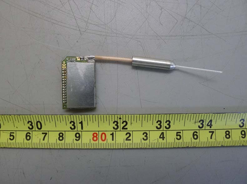
TJI-K71216
Jul 08, 20132.4GHz GFSK Transceiver module
Equipment Class
DSS - Part 15 Spread Spectrum Transmitter
TJI-KW2431
Apr 29, 20122.4GHz Digital Wireless cameras
Equipment Class
DSS - Part 15 Spread Spectrum Transmitter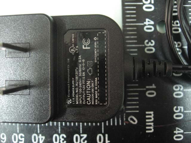
TJI-KW2430SA
Apr 29, 20122.4GHz Digital Transmission System
Equipment Class
DSS - Part 15 Spread Spectrum Transmitter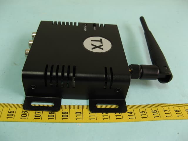
TJI-KW2425R
Aug 27, 20112.4GHz AV Sender
Equipment Class
DSS - Part 15 Spread Spectrum Transmitter