TJI-KW54055.8GHz Wireless CCD Color Camera
Kingwave Technology Co., Ltd.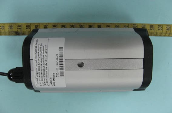
Click to zoom
Application Details
- Equipment Class
- DXX - Part 15 Low Power Communication Device Transmitter
- Date of Grant
- Mar 03, 2008
- Application Purpose
- Original Equipment
- Date of Application
- Mar 03, 2008
- Equipment Note
- 5.8GHz Wireless CCD Color Camera
- Frequency Range
- 5739.46000000 - 5866.36700000
- Country
- Taiwan
Documents & Files
Document Text
Text extracted from the exhibit documents filed with the FCC. Open a document above to read the original.
Users Manual
/5221F KW5800 12VDC 500mA 125 5725~5875M 5725~5875M Channel Frequency CH1 5740MHz CH2 5780MHz CH3 5820MHz CH4 5860MHz 1. 2. 3. 4. 5. 6. 7. 8. 5.8 4. 3. 4. ±0.5 5.8 12VDO (500mA) 5.8 e KW5221/KW5522 3. 5 Notice : The changes or modifications not expressly approved by the party responsible for compliance could void the user’s authority to operate the equipment. IMPORTANT NOTE: To comply with the FCC RF exposure compliance requirements, no change to the antenna or the device is permitted. Any change to the antenna or the device could result in the device exceeding the RF exposure requirements and void user’s authority to operate the device. 5.8 Channel Frequency CH1 5740MHz CH2 5780MHz CH3 5820MHz Ch4 5860MHz 5.8 12 CH 1 CH 3 CH 5 CH 7 DIP 1 DIP 2 DIP 3 DIP 4 ON OFF OFF OFF ON ON OFF OFF ON OFF ON ON ON ON OFF OFF 3.Selectable Channels: 8 8. IR Sensor KW5301 MANUAL 5.8GHz Wireless Multi - Receiver 5.8GHz Wireless Multi - Receiver KW5301070622-001 CHAPTER TABLE OF CONTENTS 1.CE Statement............................................................. 2.Important-Safety precautions..................................... 3.Checking Contents of Box.......................................... 4. Panel Controls and Features...................................... 5.Installation of the system........................................... 6.Orienting Device for Optimum Performance................. 7. Troubleshooting, Care and maintenance..................... 8. Specifications.......................................................... 2 2 3 4 5 9 9 10 Receiving Frequency Band Input Signal Level Range Antenna Connector Channel Input Gain Control Level Noise Figure Video Output Output Port Power connector (DC Jack) Power Supply Dimension Weight Operating temperature 5740~5860GHz -85dBm ~-10dBm SMA female connector +15~-30 dB adj. 3dB 1V p-p @ 75 ohm 4 BNC female connector 5.5Ø2.1 12VDC/2A 216mm×183mm×46mm 1420 g 0°C~50°C 8. Specifications All specification subject to change without notice 10 29 1. Important-Safety Precautions ■ To prevent fire or shock hazard, do not expose this device to rain or moisture. ■ To avoid electrical shock, do not open this device. ■ This device should be operated to use only the power supply included with it or provided as an accessory. ■ Do not overload wall outlets ■ Do not attempt to service this device yourself. Refer servicing to qualified personnel only. Note: The user is encouraged to try to correct the interference by one or more of the following measures: ■ Reorient or relocate the receiving antenna. ■ Increase distance between the equipment and receiver. ■ Connect the equipment into a different circuit outlet from the receiver's. ■ Consult with the dealer or an experienced radio/TV technician for help. Cautions: 1.Screw 5.8GHz antenna to the antenna socket at the rear of the camera first before plug in the power cord. 2.Changes or modifications are not expressly permitted. 3.Put the movable antenna as high as possible for best performance. 6.Orienting Device for Optimum Performance This device should be placed on a flat, stable surface to prevent damage to it from falling. ■ Since all homes are different for optimum reception, additional slight rotate antenna may be necessary. ■ For optimum performance you maybe rotate the channel input gain control on the device individually when you use the device. 7. Troubleshooting, Care and maintenance Please read this owner's manual carefully and follow the steps described in it. If you still have difficulties, consult the following table. It will guide you though the most common problems and their solutions Interference: Noisy picture No picture ProblemPossible solutions ■ Check all cable connections. ■ Make sure power plugs are pushed all the way in. ■ Check power switches on the digital color quad process or or digital video recorder or monitor. ■ Check the power on/off switches on the camera and the device ■ Adjust antenna orientation of camera and the device. ■ Adjust the channel input gain control of the device. ■ If using a microwave oven, turn it off. ■ Remove microwave oven from path between camera and the device. Notice : The changes or modifications not expressly approved by the party responsible for compliance could void the user’s authority to operate the equipment. IMPORTANT NOTE: To comply with the FCC RF exposure compliance requirements, no change to the antenna or the device is permitted. Any change to the antenna or the device could result in the device exceeding the RF exposure requirements and void user’s authority to operate the device. KW5301 MANUAL 5.8GHz Wireless Multi - Receiver 38 3. Checking Contents of Box Make sure that all of the items shown as below are included with your 5.8 GHz Wireless Multi-Receiver System. If something is missing, please contact your dealer as soon as possible. 1. 4 Channels Multi-Receiver 2. 2.4GHz Wireless dipole Antenna 3. Power Adapter 4. Manual In English 5.Metal Sheet for magnetic antenna x1 X1 x1 x1 ■ Operation With 4 Monitors Be sure to set the power switch on the device and monitors to the off position before processor with the following steps 1. 2. 3. 4. 5. 47 4. Panel Controls and Features The following illustrations show the names of each component,button and switch connectors on the receiver. FRONT VIEW FOR THE MULTI-RECEIVER Power ON/OFF Switch 12V Power LED Indicator 5V Power LED Indicator REAR VIEW FOR THE MULTI-RECEIVE 12V DC input power connector BNC Female Connector for CH3 Video Output BNC Female Connector for CH2 Video Output ANT SMA Female Connector BNC Female Connector for CH4 Video Output BNC Female Connector for CH1 Video Output ■ Operation With Digital Video Recorder and Monitor Be sure to set the power switch on the device and Digital Video Recorder and monitor to the off position before processor with the follow steps 5 5.Installation of the system This system is suggested to match following equipment: ̇Wireless Cameras. ̇Digital Color Quad Processor ̇Digit…
Text truncated - open the document above for the full version.
Cover Letter(s)
Compliance Certification Services Certification Division To whom it may concern: We, the undersigned, hereby authorize ELECTRONICS TESTING CENTER, TAIWAN, to act on our behalf in all manners relating to application for equipment authorization, including signing of all documents relating to these matters. Any and all acts carried out by ELECTRONICS TESTING CENTER, TAIWAN on our behalf shall have the same effect as acts of our own. We, the undersigned, hereby certify that we are not subject to a denial of federal benefits, that includes FCC benefits, pursuant to Section 5301 of the Anti-Drug Abuse Act of 1988, 21 U.S.C. 853(a). In authorizing ELECTRONICS TESTING CENTER, TAIWAN as our agent, we still recognize that we are responsible to: a) KINGWAVE TECHNOLOGY CO.,LTD. comply with the relevant provisions of the certification program; b) make all necessary arrangements for the conduct of the evaluation, including provision for examining documentation and access to all areas, records (including internal audit reports) and personnel for the purposes of evaluation (e.g. testing, inspection, assessment, surveillance, reassessment) and resolution of complaints; c) make claims regarding certification only in respect of the scope for which certification has been granted; d) do not use our product certification in such a manner as to bring the Certification Division into disrepute and not make any statement regarding our product certification which the Certification Division may consider misleading or unauthorized; e) upon suspension or cancellation of certification, discontinue use of all advertising matter that contains any reference thereto and return any certification documents as required by the Certification Division; f) use certification only to indicate the products are certified as being in conformity with specified standards; g) endeavor to ensure that no certificate or report nor any part thereof is used in a misleading manner; h) ensure that any reference to our product certification in communication media such as documents, brochures or advertising, complies with the requirements of the Certification Division; i) keep a record of all complaints made known to the us relating to the product’s compliance with requirements of the relevant standard and to make these records available to the Certification Division when requested; j) take appropriate action with respect to such complaints and any deficiencies found in products or services that affect compliance with the requirements for certification; k) document the actions taken. This authorization is valid until further written notice from the applicant. Sincerely Yours, (Please type Name and Title of Person to Receive Grant/Certificate) (Please type Company Name and Address))
Cover Letter(s)
1 Chris Harvey From: Lucy Tsai [[email protected]] Sent: Tuesday, February 05, 2008 2:49 AM To: Chris Harvey Cc: Mike Kuo Subject: FW: Fw: KINGWAVE TECHNOLOGY CO., LTD., FCC ID: TJI-KW5405, Assessment NO.: AN07T7236, Notice#1 Attachments: peak.jpg; Avg.jpg; Exhibit-G-Schematics_rev.pdf; Q4. Explanation.doc; Exhibit-I- Auth_Letter_rev.pdf; Exhibit-C-Test_Repoet rev.pdf; Exhibit-K-O_D_rev.pdf peak.jpg (633 KB)Avg.jpg (643 KB)Exhibit-G-Schematic s_rev.pdf (... Q4. planation.doc (463 K Exhibit-I-Auth_Lett er_rev.pdf ... Exhibit-C-Test_Rep oet rev.pdf... Exhibit-K-O_D_rev. pdf (27 KB) Hello Chris, Here are the response from ETC regarding Kingwave application. Please have a check. Best Regards, Lucy -----Original Message----- From: Iris Lin [mailto:[email protected]] Sent: Monday, February 04, 2008 10:56 PM To: Lucy Tsai Cc: R00/ ; R00/ Subject: Fw: Fw: KINGWAVE TECHNOLOGY CO., LTD., FCC ID: TJI-KW5405, Assessment NO.: AN07T7236, Notice#1 Dear Lucy, Ans#1: Frequency 5740-5860MHz is a nominal frequency and 5739.460-5866.367 MHz is a peak frequency. Due to this EUT is a wideband signal device, so the actual operation frequency will not be exactly located at central point as nominal frequency. Therefore, frequency 2739.460-5866.367 is the correct and actual peak frequency. 37.4dB to 37.6dB are the correction factor. We add an attenuator which is about 20dB during the testing of the main frequency in order to protect for our testing instrument. We are afraid our testing instrument will be broken because of the high frequency. Therefore, the factor will be higher than the normal factor because of the additional attenuator. Ans#2: Please refer to the attached peak & average diagram. Ans#3: Please refer to the updated shcematic as attachment. Ans#4: Please refer to the attached explanation as word file. Ans#5: Please refer to the updated authority letter as attachment. Ans#6: Please refer to the updated report as attachment. Ans#7: Please refer to the updated operation description as attachment. 2 Ans#8: Yes, the EUT was pretested with different orientation and the worst case was final tested. If you have any question, please let us know ASAP. ELECTRONICS TESTING CENTER, TAIWAN IRIS LIN ( ) TEL: 886-2-26023052 ext.10 FAX: 886-2-26010910 ----- Original Message ----- From: "SS" <[email protected]> To: "R00/ " <[email protected]> Sent: Thursday, October 04, 2007 8:47 AM Subject: Fw: KINGWAVE TECHNOLOGY CO., LTD., FCC ID: TJI-KW5405, Assessment NO.: AN07T7236, Notice#1 > > ----- Original Message ----- > From: <[email protected]> > To: <[email protected]> > Cc: <[email protected]> > Sent: Tuesday, October 02, 2007 8:19 PM > Subject: KINGWAVE TECHNOLOGY CO., LTD., FCC ID: TJI-KW5405, Assessment NO.: > AN07T7236, Notice#1 > > > > Dear SS Liou, > > > > You are listed as the Technical Contact for the above referenced TCB > application. The following item(s) need(s) to be resolved before the review > can be continued: > > > > 1. The specifications for this device state that it operates on 5740 > > MHz > low channel and 5860 MHz high channel. The test data shows that this > may actually operate at 5739.460 MHz and 5866.367 MHz. Please confirm > that this > is the correct actual operating frequencies. Also, please explain the 37.4 > to 37.6 dB correction factor used on the fundamental emission > measurements table. > > > > 2. The test report indicates that this device uses Frequency Modulation. > The Average measurements are approximately 15dB lower than the Peak > emissions, which seems to be a large difference. Please explain this > difference for an FM signal (additional plots may help explain this > difference). > > > > 3. Please provide the RF schematics of the Tx Module (shown as a > > block U5 > on the schematics submitted). > > > > 4. There seems to be a large ferrite core that was added to the > > power cord > of this device. Please submit confirmation from the applicant that > this modification will be incorporated into every unit marketed. > Also, the external photos show a power supply with a DC plug on the > end, but the internal photos show a hard-wired power cord with a > strain-relief on the enclosure. Please explain the difference and 3 > confirm which power supply and > connection is used for this device. > > > > 5. Please submit a letter of authorization that is dated within 1 > > year > (also please update to the current CCS address in Fremont, CA). > > > > 6. FCC 15.215 requires that the 20dB BW be contained within the > > allowed > 5725 - 5875 MHz band. Please show the 20dB Occupied Bandwidth plots > of low > and high channels to ensure compliance with FCC 15.215. > > > > 7. Also, there is a recommendation to stay within the central 80% of > > the > band, which would be 5740 - 5860 MHz. While this device operates > outside that central 80% of the band, the 20dB BW plots may show that > compliance with this recommendation is not necessary. Please include > information in the Operational Description exhibit about frequency > generation and stabilization. > > > > 8. Was the EUT and antenna oriented in different axes to determine > > worst > case emissions? > > > > The items indicated above must be submitted before processing can continue > on the above referenced application. Failure to provide the requested > information within 30 days of the original e-mail date may result in > application dismissal and forfeiture of the filing fee. Also, please > note that partial responses increase processing time and should not be submitted. > Any questions about the content of this correspondence should be > directed to > the e-mail address listed below the name of the sender. > > > > Best regards, > > > > Chris Harvey > > [email protected] > > >
Cover Letter(s)
The power supply is pluged-in the EUT connector here.
External Photos
ETC Report No. : 07-08-RBF-107-01 FCC ID.: TJI-KW5405 Rev. No 1.0 CONSTRUCTED PHOTOS of EUT Top View of EUT Bottom View of EUT ETC Report No. : 07-08-RBF-107-01 FCC ID.: TJI-KW5405 Rev. No 1.0 CONSTRUCTED PHOTOS of EUT Front View of EUT Side View of EUT ETC Report No. : 07-08-RBF-107-01 FCC ID.: TJI-KW5405 Rev. No 1.0 CONSTRUCTED PHOTOS of EUT Rear View of EUT Side View of EUT ETC Report No. : 07-08-RBF-107-01 FCC ID.: TJI-KW5405 Rev. No 1.0 CONSTRUCTED PHOTOS of EUT Adapter Top View of Adapter Bottom View of Adapter
ID Label/Location Info
50mm 25mm
Internal Photos
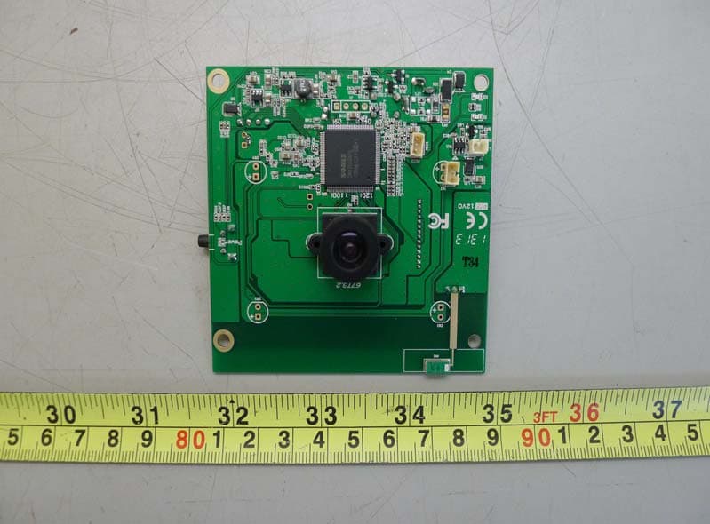
ETC Report No. : 07-08-RBF-107-01 FCC ID.: TJI-KW5405 Rev. No 1.0 CONSTRUCTED PHOTOS of EUT Internal View of EUT ETC Report No. : 07-08-RBF-107-01 FCC ID.: TJI-KW5405 Rev. No 1.0 CONSTRUCTED PHOTOS of EUT Component View of PCB Component View of PCB ETC Report No. : 07-08-RBF-107-01 FCC ID.: TJI-KW5405 Rev. No 1.0 CONSTRUCTED PHOTOS of EUT Component View of PCB Solder View of PCB ETC Report No. : 07-08-RBF-107-01 FCC ID.: TJI-KW5405 Rev. No 1.0 CONSTRUCTED PHOTOS of EUT Component View of PCB Component View of PCB ETC Report No. : 07-08-RBF-107-01 FCC ID.: TJI-KW5405 Rev. No 1.0 CONSTRUCTED PHOTOS of EUT Component View of PCB Component View of PCB ETC Report No. : 07-08-RBF-107-01 FCC ID.: TJI-KW5405 Rev. No 1.0 CONSTRUCTED PHOTOS of EUT Solder View of PCB ETC Report No. : 07-08-RBF-107-01 FCC ID.: TJI-KW5405 Rev. No 1.0 CONSTRUCTED PHOTOS of EUT Antenna Antenna ETC Report No. : 07-08-RBF-107-01 FCC ID.: TJI-KW5405 Rev. No 1.0 CONSTRUCTED PHOTOS of EUT Component View of Adapter’PCB Solder View of Adapter’PCB
Test Report
Rev. No 1.0 FCC Part 15 EMI TEST REPORT of E.U.T. 5.8GHz Wireless CCD Color Camera FCC ID TJI-KW5405 MODEL KW5221F for APPLICANT : KINGWAVE TECHNOLOGY CO., LTD. ADDRESS : 18F-3, No. 186, Jian-Yi Road, Chung-Ho City, 235, Taipei, Taiwan Test Performed by ELECTRONICS TESTING CENTER, TAIWAN NO. 34. LIN 5. DINGFU TSUEN, LINKOU SHIANG TAIPEI COUNTY, TAIWAN, 24442, R.O.C. Tel:(02)26023052 Fax:(02)26010910 http://www.etc.org.tw ; e-mail : [email protected] Report Number : 07-07-RBF-132-01 ETC Report No. : 07-08-RBF-107-01 FCC ID. : TJI-KW3208 Rev. No 1.0 TEST REPORT CERTIFICATION Applicant : KINGWAVE TECHNOLOGY CO., LTD. 18F-3, No. 186, Jian-Yi Road, Chung-Ho City, 235, Taipei, Taiwan Manufacturer : KINGWAVE TECHNOLOGY CO., LTD. 18F-3, No. 186, Jian-Yi Road, Chung-Ho City, 235, Taipei, Taiwan Description of EUT : a) Type of EUT : 5.8GHz Wireless CCD Color Camera b) Trade Name : KINGWAVE c) Model No. : KW5221F d) Power Supply : I/P: 100-240VAC, 50/60Hz, 0.5A; O/P: DC12V, 1A e) Frequency Range : 5740~5860 MHz Regulation Applied : FCC Rules and Regulations Part 15 Subpart C (2007) I HEREBY CERTIFY THAT: The data shown in this report were made in accordance with the procedures given in ANSI C63.4 (2003), and the energy emitted by the device was founded to be within the limits applicable. I assume full responsibility for accuracy and completeness of these data. Note: 1. The result of the testing report relate only to the item tested. 2. The testing report shall not be reproduced expect in full, without the written approval of ETC. Date Test Item Received : Aug. 21, 2007 Date Test Campaign Completed : Sep. 03, 2007 Date of Issue : Sep. 27, 2007 Test Engineer : (falcon Shi) Approve & Authorized Signer : Will Yauo, Manager EMC Dept. II of ELECTRONICS TESTING CENTER, TAIWAN ETC Report No. : 07-08-RBF-107-01 FCC ID. : TJI-KW3208 Rev. No 1.0 Table of Contents Page 1 GENERAL INFORMATION.......................................................................................................1 1.1 Product Description........................................................................................................................1 1.2 Characteristics of Device................................................................................................................1 1.3 Test Methodology..........................................................................................................................1 1.4 Test Facility....................................................................................................................................1 2 PROVISIONS APPLICABLE.......................................................................................................2 2.1 Definition........................................................................................................................................2 2.2 Requirement for Compliance...........................................................................................................3 2.3 Restricted Bands of Operation........................................................................................................5 2.4 Labeling Requirement.....................................................................................................................5 2.5 User Information............................................................................................................................6 3 SYSTEM TEST CONFIGURATION...........................................................................................7 3.1 Justification.....................................................................................................................................7 3.2 Devices for Tested System.............................................................................................................7 4 RADIATED EMISSION MEASUREMENT..............................................................................8 4.1 Applicable Standard.......................................................................................................................8 4.2 Measurement Procedure.................................................................................................................8 4.3 Measuring Instrument...................................................................................................................10 4.4 Radiated Emission Data................................................................................................................11 4.5 Field Strength Calculation.............................................................................................................15 4.6 Photos of Radiation Measuring Setup............................................................................................16 5 CONDUCTED EMISSION MEASUREMENT........................................................................17 5.1 Standard Applicable.....................................................................................................................17 5.2 Measurement Procedure...............................................................................................................17 5.3 Conducted Emission Data.............................................................................................................18 5.4 Result Data Calculation.................................................................................................................20 5.5 Conducted Measurement Equipment.............................................................................................20 5.6 Photos of Conduction Measuring Setup........................................................................................21 6 ANTENNA REQUIREMENT....................................................................................................22 6.1 Standard Applicable.....................................................................................................................22 6.…
Text truncated - open the document above for the full version.
Test Setup Photos
ETC Report No. : 07-08-RBF-107-01 FCC ID.: TJI-KW5405 Rev. No 1.0 4.6 Photos of Radiation Measuring Setup ETC Report No. : 07-08-RBF-107-01 FCC ID.: TJI-KW5405 Rev. No 1.0 5.6 Photos of Conduction Measuring Setup
Contact Information
Applicant
Ming-Shan Chan(Engineer)
Test Firm
Electronics Testing Center, TaiwanWill Yauo
Technical Specifications
| # | Rule Parts | Frequency Range | Power Output |
|---|---|---|---|
| 1 | 15C | 5.74 GHz - 5.87 GHz | - |
Other Applications from Kingwave Technology Co., Ltd.
TJI-K71216P
Jul 16, 20132.4GHz GFSK Transceiver module
Equipment Class
DSS - Part 15 Spread Spectrum Transmitter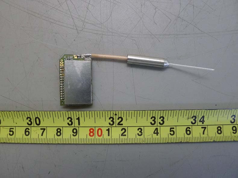
TJI-K71216
Jul 08, 20132.4GHz GFSK Transceiver module
Equipment Class
DSS - Part 15 Spread Spectrum Transmitter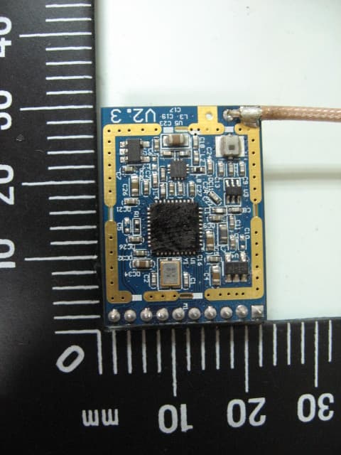
TJI-KWS7S3
May 23, 20122.4GHz RF Module
Equipment Class
DSS - Part 15 Spread Spectrum Transmitter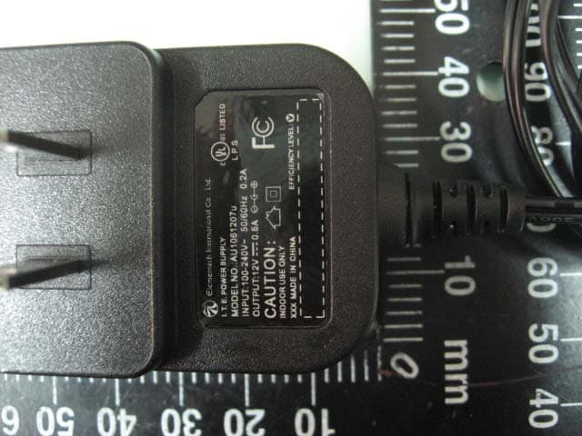
TJI-KW2431
Apr 29, 20122.4GHz Digital Wireless cameras
Equipment Class
DSS - Part 15 Spread Spectrum Transmitter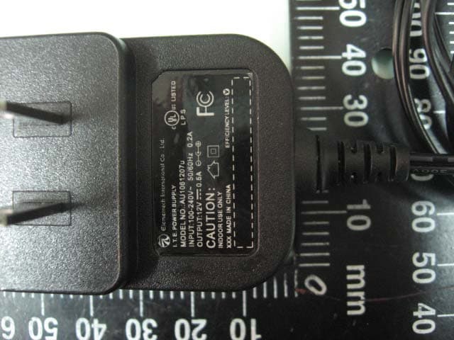
TJI-KW2430SA
Apr 29, 20122.4GHz Digital Transmission System
Equipment Class
DSS - Part 15 Spread Spectrum Transmitter