TL4096150Wireless Laser Desktop Mouse 2.4GHz
Verbatim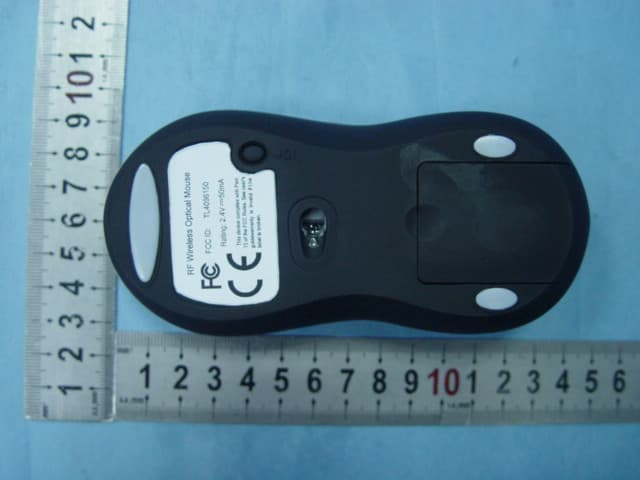
Click to zoom
Application Details
- Equipment Class
- DXX - Part 15 Low Power Communication Device Transmitter
- Date of Grant
- Jan 09, 2007
- Application Purpose
- Original Equipment
- Date of Application
- Jan 09, 2007
- Equipment Note
- Wireless Laser Desktop Mouse 2.4GHz
- Frequency Range
- 2469.00000000 - 2469.00000000
- Company
- Verbatim
- Country
- United States
Documents & Files
Document Text
Text extracted from the exhibit documents filed with the FCC. Open a document above to read the original.
Users Manual
Rechargeable 5keys Wireless Mouse User Manual Welcome Thank you for selecting this product! Your RF wireless optical mouse uses a newly developed RF wireless technology 2.4GHz that replaces the traditional wired mouse. You can use your wireless optical mouse freely and improve your efficiency and enjoy your beautiful life from the high technology. The accessory laid charger frees you out of changing batteries frequently. Product Features 1. Radio frequency 2.4GHz, enjoy your freely wireless space 2. It has 65000 ID code, there is no interference even many mice being used at the same time. 3. 5Keys.Automatically save power sleeping functions, battery life be prolonged. 4. Receiver and charger 2 in 1 let the batteries been charging up at any time. 5. Inner rechargeable function. Systems Compatibility IBM PC and Win 95/98/Me/2000/XP,No need driver The Steps of Install Battery 1. Please prepare for two PCS new AAA alkaline batteries 2. Press the button of the mouse upper cover and pull the battery cover rearward (Please see the reference picture) 3. Please insert the batteries correctly according to the polarity marks of the battery grooves. Pull the battery covers forward, when you hear “crack” sound, which shows the battery cove r is locked successfully. Receiver Installation 1. If you use PS/2 connector, please use the USB to PS/2 adaptor and connect with the connector before your charger is working, the indication light is red, and when charging finished, the indication light turns green. 2. In order not to waste the power of batteries unexpectedly, we advised you to put the mouse on the charger when you finished using it. But you should pay attention to the charging time. 3.This charger should be linked directly to electrical source of 5V with USB/PS2 connector, and it takes almost 5 hours to charge up. Connect: 1 , The mouse should be near with the receiver, 2 , Pls push the receiver’s ligher. 3 , Please push the ID button at the buttom of the mouse within 10 seconds. Please note the rechargeable time will depends on the battery different. ① Left key ② right key ③ middle key ④、⑤ automatic keys The drive install Please take the drive and made it according to the following instructions. Please click “next” ① ② ③ ④ “next” ⑤ The styerm remind “input the address. Please click “next” “Next “and “copy” restart computer Automatic Keys setup. There will be shows a remaked when restarted. System default(Intelli-Mouse) mode Enhanced scroll mode Scroll ** lines per scroll unit Scroll one page scroll unit please click and next. Auto scroll Back space Close Application Connect To Internet Control Lock Control Panel Copy Cut Delete Double click Down Drag Lock End Enter Esc Explorer F1~F10 Find computer Find File Home Horizontal wheel Internet Explorer Backward Internet Explorer forward Launch Default Browser Launch Default E-mail Left Maximize Window Middle Button Minimize All Windows Minimize windows Page Down Page Up Paste Redo Right Run Shift Lock Space Start Menu System Default System Help System Property Tab Undo Undo Minimize All Windows Universal Scroll Universal Zoom Up Attention Please 1. Please don’t make the mouse far away from the receiver in order to work more smoothly. 2. You’d better use the mouse on the white desk, in this way the batteries can be used in a longer time. Please remove the batteries if the mouse will not be used for a long time. .3. This mouse with saving power sleeping functions, please press any key or scroll the wheel to wake up the mouse when it is sleeping. 4 . If you want to take off the mouse power, please continue to press the ID switch of the mouse bottom over 3 seconds. If you want to take on the power, please click the ID switch once again. Caution Any changes or modifications not expressly approved by the party responsible for compliance could void the user's authority to operate the equipment. Note FCC Statement:: 1.This device complies with Part 15 of the FCC Rules. Operation is subject to the following two conditions:(1)This device may not cause harmful interference, and(2)This device must accept any interference received, including interference that may cause undesired operation. 2.Changes or modifications not expressly approved by the party responsible for compliance could void the user’s authority to operate the equipment. These limits are designed to provide reasonable protection against harmful interference in a residential installation. This equipment generates, uses and can radiate radio frequency energy and, if not installed and used in accordance with the instructions, may cause harmful interference to radio communications. However, there is no guarantee that interference will not occur in a particular installation. If this equipment does cause harmful interference to radio or television reception, which can be determined by turning the equipment off and on, the user is encouraged to try to correct the interference by one or more of the following measures: * Reorient or relocate the receiving antenna. * Increase the separation between the equipment and receiver. * Connect the equipment into an outlet on a circuit different from that to which the receiver is connected. * Consult the dealer or an experienced radio/TV technician for help.
Block Diagram
Block Diagram Optical sensor U2 Antenna RF Generator X1 oscillation 16MHZ MCU U2 Y1 oscillation 6MHZ RF Amplifier FM Modulator 2.4GHZ TX 2.4GHZ U6 DC-DC Steup Recharge Part Key &Encoder C A B
Operational Description
96150 TX Operation Description Modulation Type: FM TX Frequency: 2469 MHz 96150 is an optical and wireless mouse with frequency 2.4 GHz. The remote control distance reaches 10 meters. It contains rechargeable battery and may be charged from USB port. The mouse is designed with 4 parts: Optical sensor U3 (A7050),MCU U1 (HT82K68E), RF1 module and EEPROM U2 (24LC02). Q1 and Q2 etc. form circuits of charging and RF automatic stop function. U6 converts battery voltage to a stable DC 3V for supplying the mouse. U1 receives signals of SWR, SWL and SWM when working. When the mouse moved by a user, Optical sensor U3 detects the movement and send a signal to U1. All signals are processed in U1 and are encoded. RF1 is a wireless module. It contains of functions of modulation, amplification and transmission by antenna. Q1 and Q2 etc. form a charging circuit to charge batteries when their voltage less than 2.9V. Charging is stop automatically when batteries are fully charged. * END *
Schematics
1234 A B C D 4321 D C B A Title NumberRevisionSize A4 Date:26-Dec-2006Sheetof File:E:\yuheping\RD\sch\sch.ddbDrawn By: CE 1 CSN 2 SCLK 3 MOSI 4 MISO 5 I R Q 6 V D D 7 V S S 8 X C 2 9 X C 1 1 0 VDD_PA 11 ANT1 12 ANT2 13 VSS 14 VDD 15 I R E F 1 6 V S S 1 7 V D D 1 8 D V D D 1 9 V S S 2 0 U1 NRF24L01 R2 22K R3 10R R11M C7 33nF C1 22pF C2 22pF C3 2200pF C9 0.01uF + C16 4.7uF C8 1000pF C4 4.7pF C51.0pF C10 1.0pF X1 16MHZ L1 4.7nH L23.3nH L3 3.9nH ANT1 PCB ANT RFVCC RF_CE RF_CS SCLK MOSI MISO IRQ NRF2401(2)RF MODEL
Test Report
Page 1of 33 FCC ID: TL4096150 ACCURATE TECHNOLOGY CO. LTD REPORT NO. ATE20062722 FCC CERTIFICATION On Behalf of Verbatim Wireless Laser Desktop Mouse 2.4GHz Model No.: 96150 FCC ID: TL4096150 Prepared for : Verbatim Address : 1200 West W.T. Harris Blvd. Charlotte, North Carolina 28262, USA Prepared by : ACCURATE TECHNOLOGY CO. LTD Address : F1, Bldg. A, Changyuan New Material Port, Keyuan Rd. Science & Industry Park, Nanshan, Shenzhen, Guangdong P.R. China Tel: (0755) 26503290 Fax: (0755) 26503396 Report Number : ATE20062722 Date of Test : December 22, 2006 Date of Report : December 25, 2006 Page 2of 33 FCC ID: TL4096150 ACCURATE TECHNOLOGY CO. LTD REPORT NO. ATE20062722 TABLE OF CONTENTS Description Page Test Report Certification 1. GENERAL INFORMATION.......................................................................................................... 4 1.1. Description of Device (EUT)....................................................................................................................4 1.2. Description of Test Facility......................................................................................................................4 1.3. Measurement Uncertainty.........................................................................................................................4 2. MEASURING DEVICE AND TEST EQUIPMENT..................................................................... 5 3. CONDUCTED EMISSION FOR FCC PART 15 SECTION 15.107(A)...................................... 6 3.1. Block Diagram of Test Setup....................................................................................................................6 3.2. The Emission Limit For Section 15.107(a)..............................................................................................6 3.3. EUT Configuration on Measurement.......................................................................................................7 3.4. Operating Condition of EUT....................................................................................................................7 3.5. Test Procedure..........................................................................................................................................7 3.6. Power Line Conducted Emission Measurement Results..........................................................................8 4. RADIATED EMISSION FOR FCC PART 15 SECTION 15.109(A)........................................... 9 4.1. Block Diagram of Test Setup....................................................................................................................9 4.2. The Field Strength of Radiation Emission Measurement Limits..............................................................9 4.3. Configuration of EUT on Measurement.................................................................................................10 4.4. Operating Condition of EUT..................................................................................................................10 4.5. Test Procedure........................................................................................................................................10 4.6. The Field Strength of Radiation Emission Measurement Results..........................................................11 5. FUNDAMENTAL AND HARMONICS RADIATED EMISSION MEASURMENT.............. 12 5.1. Block Diagram of Test Setup..................................................................................................................12 5.2. The Emission Limit................................................................................................................................12 5.3. Configuration of EUT on Measurement.................................................................................................13 5.4. Operating Condition of EUT..................................................................................................................13 5.5. Test Procedure........................................................................................................................................13 5.6. The Field Strength of Radiation Emission Measurement Results..........................................................14 6. RADIATED EMISSION FOR FCC PART 15 SECTION 15.249(D)......................................... 15 6.1. Block Diagram of Test Setup..................................................................................................................15 6.2. The Emission Limit For Section 15.249(d)............................................................................................15 6.3. EUT Configuration on Measurement.....................................................................................................17 6.4. Operating Condition of EUT..................................................................................................................17 6.5. Test Procedure........................................................................................................................................17 6.6. The Emission Measurement Result........................................................................................................18 7. BAND EDGES................................................................................................................................. 19 7.1. The Requirement....................................................................................................................................19 7.2. EUT Configuration on Measurement.....................................................................................................19 7.3. Operating Condition of EUT..................................................................................................................19 7.4. Test Procedure..............................................................................................................…
Text truncated - open the document above for the full version.
Contact Information
Applicant
Steve Armfield(Executive Director of Engineering)
Test Firm
Accurate Technology Co., Ltd.Sean Liu
Technical Specifications
| # | Rule Parts | Frequency Range | Power Output |
|---|---|---|---|
| 1 | 15C | 2.47 GHz - 2.47 GHz | - |
Other Applications from Verbatim
TL4-3187288-32301
Apr 24, 2026Portable SSD
Equipment Class
DTS - Digital Transmission System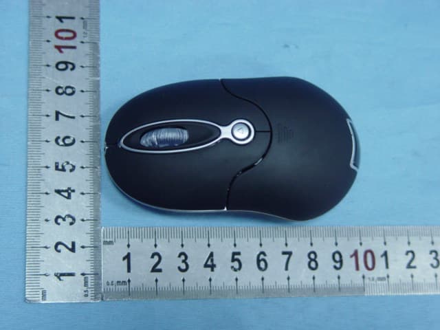
TL496147
Apr 04, 20072.4GHz Wireless Optical Notebook Mouse
Equipment Class
DXX - Part 15 Low Power Communication Device Transmitter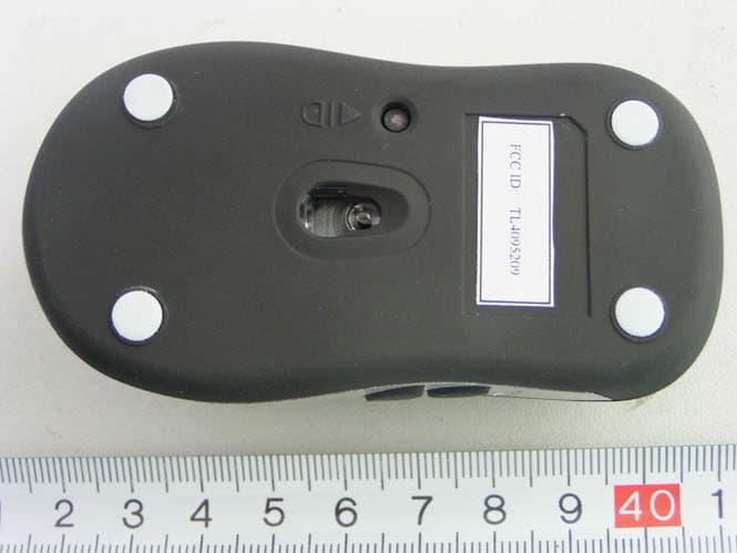
TL4095209
Sep 14, 2005Wireless Optical Mouse
Equipment Class
DXX - Part 15 Low Power Communication Device Transmitter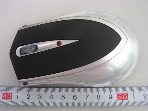
TL4095208
Sep 14, 2005Wireless Optical Mouse
Equipment Class
DXX - Part 15 Low Power Communication Device Transmitter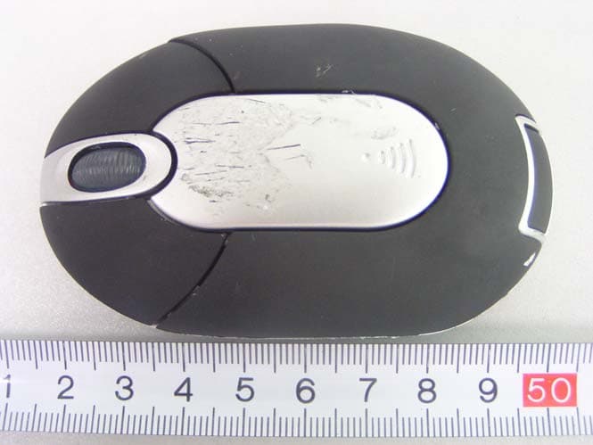
TL4095210
Sep 14, 2005Wireless Optical Mouse
Equipment Class
DXX - Part 15 Low Power Communication Device Transmitter