TMAELK-6010KEYFOB TRANSCEIVER
ELK Products, Inc.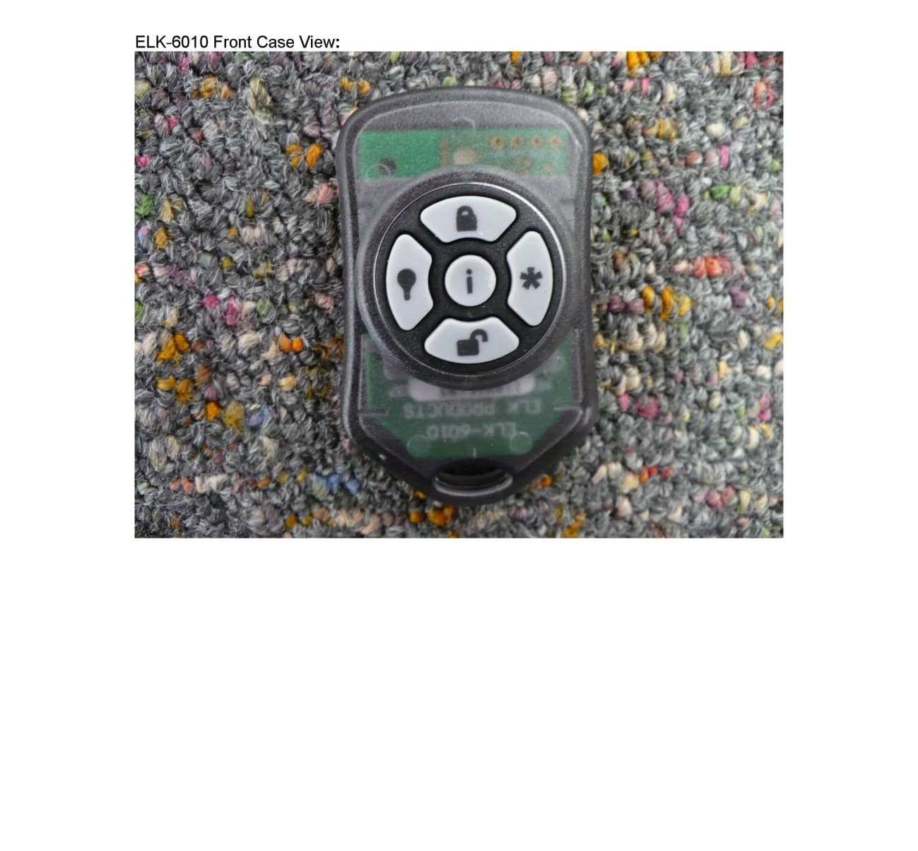
Click to zoom
Application Details
- Equipment Class
- DXX - Part 15 Low Power Communication Device Transmitter
- Date of Grant
- Aug 08, 2011
- Application Purpose
- Original Equipment
- Date of Application
- Aug 08, 2011
- Equipment Note
- KEYFOB TRANSCEIVER
- Frequency Range
- 902.96000000 - 926.68000000
- Company
- ELK Products, Inc.
- Country
- United States
Documents & Files
Document Text
Text extracted from the exhibit documents filed with the FCC. Open a document above to read the original.
Users Manual
The ELK-6010 Keychain Remote “Fob” Transceiver is smalland lightweight handheld device. It features 5 pushbuttons, 1for system status inquiry, and 4 which may be programmed toperform system functions. The 6010 is compatible with Elk’sTwo-Way Wirele ss Technology Receivers, which currently includes the ELK-M1 model M1XRFTW. Stand-alone “Slavereceivers” with voltage/relay outputs are also being designed. Keychain Remote “Fob” Transciever ELK-6010 Enrolling, Programming, and Testing with M1 Control1. Enter Keypad Installer Level Programming and navigate to Menu 14 - Wireless Definitions2. Press the right arrow and scroll or navigate to Option 3 - Learn Wireless Transmitter.3. Press the right arrow and scroll or navigate to the first desired zone number.4. Press the right arrow to activate the enroll mode. The keypad will display Push Transmitter Button and the M1 will speak “Press Transmitter button for zone xx. 5. Press and hold any one of the 5 buttons on the 6010.6. Upon successful enrollment the keypad will briefly display the ID of the new transmitter and M1 will speak “Zone xx Enrollment.” [If not successful try repeat the process again.] The Transmitter ID (TXID) is 6 hexadecimal digits. For a Keychain Remote “FOB” the 1st digit will be “F”followed by 5 digits of “0” to “F”. Examples: F12345, F9ABCF. This TXID is printed on the device and thepackaging. 7. The Rapid Enroll feature of M1 will advance to the next zone automatically. M1 will speak “Press Transmitter button for zone xx (the next zone) and wait for you to install the battery in the next transmitter. 8. For each additional transmitter begin at step 4. When enrollment is completed press the ELK key twice.9. Navigate to Menu 5 - Zone Definitions and program the Zone Definition for each wireless sensor. For a Keychain Remote “Fob” program the Zone Definition as “Keyfob”. 10. Perform a Test of every sensor using the Keypad Walk Test (User Menu 3). In the Elk M1 Control there are factory default definitions for the the buttons: Button #1 (top position printed with a secure padlock symbol) will Arm the M1.Button #2, (bottom position printed with a unsecure padlock symbol) will DISARM the M1.Button #3, (left position printed with a light bulb symbol) is available for use by the installer.Button #4, (right position printed with a asterisk symbol) is available for use by the installer.Button #9, (center position printed with “i” for inquiry) will query the M1 for current status. SPECIFICA TIONS: Low Profile Dimensions: .45” H x 1.37” W x 2.24” LBattery: CR2032 coin cell, 3 volt. Service life of up to 5 years dependent on transmission power level and usage.Frequency: 902 Mhz - 928 Mhz (frequency hopping over 50 channels)Supervisor Check-in Intervals: N/A Keychain Remotes are not intended to be supervisedTransmission Duration (on-time): 50 milliseconds to transmit its data and receive an acknowledgement.Anti-Jamming: Frequency hopping and short transmission time makes Elk’s sensor difficult to detect or jam.BATTERY INST ALLA TION AND REPLACEMENT Using a small screwdriver, pry apart the unit at the mid line. Be careful when dividing the two halves. Partiallyremove the printed circuit board until you are able to slide out the old battery from its holder. Replace with afresh new battery, then reposition the circuit board and snap the two halves back together. W arning: Do not reverse the battery direction. Using ElkRP Remote Program Software to add Wireless Sensors to M11. On the ElkRP Account Details screen open Wireless Setup.2. Navigate to the Transmitters tab and double click the desired Zone number.3. Place a check mark in the Enabled box. Because this is a Keychain Remote, select the Supervision type as: 0=Not Supervised. Keychain Remotes DO NOT send supervisory check-in signals since they typically arecarried off-site by the user. 4. Type in the TXID number of the Keychain Remote as printed on the sensor and the packaging.5. Click Save.6. Navigate to Menu 5 - Zone Definitions and program the Zone Definition for the 6010 as “Keyfob”.7. Perform a Test of every sensor using the Keypad Walk Test (User Menu 3).Operation and TestingOperating the 6010 Keychain Remote “Fob” is very straightforward:1. Select the desired button.2. Press and hold the button for at least 1 full second.3. You should receive the following feedbacks: a. The operation to which the button is programmed should occur.b. The bi-color LED on the 6010 will illuminate as part of the two-way feedback from the control and receiver. 4. In most cases the definition or meaning of the bi-color LED on the 6010 will depend on the button pressed:SOLID GREEN If button #2 (Disarm) or #9 (Info Status) was pressed this indicates the Control is presently Disarmed.If button #1 (Arm) was pressed, this indicates the Control was unable to Arm possibly due to a violated zone.If button #3 or #4 was pressed this indicates the message was received and asknowledged by the Control. RED If button #1 (Arm) or #9 (Info Status) was pressed this indicates the Control was (or just has been) Armed.If button #2 (Disarm) was pressed this indicates the Control is Armed and that the attempt to disarm failed. Blinking RED Alarm Memory - Alarm has been activated Featuring Elk’s Industry Leading Two-Way Supervised Wireless Technology. FCC COMPLIANCE STATEMENT: This device complies with Part 15 of the FCC Rules. Operation is subject to the following two conditions:(1) this device may not cause harmful interference, and(2) this device must accept any interference received, including interference that may cause undesired operation.ELK-6010 KeyChain Remote "FOB" FCC ID: TMA ELK-6010 NOTE: ELK PRODUCTS IS NOT RESPONSIBLE FOR ANY CHANGES OR MODIFICATIONS NOTEXPRESSLY APPROVED BY THE PART Y RESPONSIBLE FOR COMPLIANCE. SUCH MODIFICATIONS COULD VOID THE USER’S AUTHORITY TO OPERATE THE EQUIPMENT. 6/13/2011 Page 1 Page 2
External Photos
ELK PRODUCTS INC. FCC ID: TMAELK-6010
ID Label/Location Info
ELK-6010 Inside PCB Top, FCC Label View: ELK-6010 FCC Label On Back Case Position:
Internal Photos
ELK-6010 PCB Back And Button Elastomer
Test Report
FCC PART 15.249 TEST REPORT UNLICENSED INTENTIONAL RADIATOR Applicant ELK PRODUCTS, INC. Address 3266 HIGHWAY 70 WEST HILDEBRAN NC 28637 USA FCC ID TMAELK-6010 Product Description KEYFOB TRANSCEIVER Date Sample Received 5/17/2011 Date Tested 5/17/2011 Tested By Nam Nguyen Approved By Mario de Aranzeta Report Number 1019AT11TestReport.doc Test Results PASS FAIL THE ATTACHED REPORT SHALL NOT BE REPRODUCED EXCEPT IN FULL WITHOUT THE WRITTEN APPROVAL OF TIMCO ENGINEERING, INC. 849 NW State Road 45 Newberry, FL 32669 USA Ph: 888.472.2424 or 352.472.5500 Fax: 352.472.2030 Email: [email protected] Website: www.timcoengr.com Certificate # 0955-01 APPLICANT: ELK PRODUCTS, INC. FCC ID: TMAELK-6010 REPORT #: E\ELK_TMA\1019AT11\1019AT11TestReport.doc Page 2 of 13 Mdea 9.20.2007 TABLE OF CONTENT GENERAL REMARKS ....................................................................................................... 3 GENERAL INFORMATION ................................................................................................. 4 EMC EQUIPMENT LIST .................................................................................................... 5 TEST PROCEDURES ........................................................................................................ 6 RADIATION INTERFERENCE ............................................................................................ 7 OCCUPIED BANDWIDTH.................................................................................................. 9 BAND EDGE COMPLIANCE ............................................................................................ 10 DUTY CYCLE ................................................................................................................. 12 POWER LINE CONDUCTED INTERFERENCE .................................................................. 13 APPLICANT: ELK PRODUCTS, INC. FCC ID: TMAELK-6010 REPORT #: E\ELK_TMA\1019AT11\1019AT11TestReport.doc Page 3 of 13 Mdea 9.20.2007 GENERAL REMARKS The attached report shall not be reproduced except in full without the written permission of Timco Engineering Inc. Summary The device under test does: fulfill the general approval requirements as identified in this test report not fulfill the general approval requirements as identified in this test report Attestations This equipment has been tested in accordance with the standards identified in this test report. To the best of my knowledge and belief, these tests were performed using the measurement procedures described in this report. All instrumentation and accessories used to test products for compliance to the indicated standards are calibrated regularly in accordance with ISO 17025 requirements. Certificate # 0955-01 I attest that the necessary measurements were made, under my supervision, at: Timco Engineering Inc. 849 NW State Road 45 Newberry, Fl 32669 Authorized Signatory Name: Mario de Aranzeta C.E.T. Compliance Engineer/ Lab. Supervisor Date: 5/19/2011 APPLICANT: ELK PRODUCTS, INC. FCC ID: TMAELK-6010 REPORT #: E\ELK_TMA\1019AT11\1019AT11TestReport.doc Page 4 of 13 Mdea 9.20.2007 GENERAL INFORMATION DUT Specification The test results relate only to the items tested. Applicable Standard Part 15.249 DUT Description KEYFOB TRANSCEIVER FCC ID TMAELK-6010 Operating Frequency TX: (902.96 – 926.68) MHz RX: Same No. of Channels 50 Modulations GFSK DUT Power Source 110–120Vac/50– 60Hz DC Power Battery Operated Exclusively Test Item Prototype Pre-Production Production Type of Equipment Fixed Mobile Portable Test Facility Timco Engineering Inc. located at 849 NW State Road 45 Newberry, FL 32669 USA. Test Conditions Temperature: 26ºC Relative humidity: 50% Test Exercise The DUT was placed in continuous transmit mode of operation. Modifications Test Supporting Equipment Supporting Device Manufacturer Model / FCC ID Serial Number N/A APPLICANT: ELK PRODUCTS, INC. FCC ID: TMAELK-6010 REPORT #: E\ELK_TMA\1019AT11\1019AT11TestReport.doc Page 5 of 13 Mdea 9.20.2007 EMC EQUIPMENT LIST Device Manufacturer Model Serial Number Cal/Char Date Due Date 3-Meter Semi- Anechoic Chamber Panashield N/A N/A Listed 3/10/10 3/10/12 AC Voltmeter HP 400FL 2213A14499 CAL 3/23/09 3/23/12 Antenna: Dipole Kit Electro- Metrics TDA-30/1-4 153 CHAR 7/10/09 7/10/11 Frequency Counter HP 5385A 3242A07460 CAL 5/26/09 5/26/12 Hygro- Thermometer Extech 445703 0602 CAL 1/30/09 1/30/12 Modulation Analyzer HP 8901A 3435A06868 CAL 5/26/09 5/26/12 Digital Multimeter Fluke FLUKE-77-3 79510405 CAL 5/18/09 5/18/12 Analyzer Tan Tower Preamplifier HP 8449B-H02 3008A00372 CAL 11/21/09 11/21/11 Analyzer Tan Tower Quasi- Peak Adapter HP 85650A 3303A01690 CAL 11/22/09 11/22/11 Analyzer Tan Tower RF Preselector HP 85685A 3221A01400 CAL 11/21/09 11/21/11 Analyzer Tan Tower Spectrum Analyzer HP 8566B Opt 462 3138A07786 3144A20661 CAL 11/24/09 11/24/11 Temperature Chamber Tenney Engineering TTRC 11717-7 CHAR 4/25/10 4/25/12 APPLICANT: ELK PRODUCTS, INC. FCC ID: TMAELK-6010 REPORT #: E\ELK_TMA\1019AT11\1019AT11TestReport.doc Page 6 of 13 Mdea 9.20.2007 TEST PROCEDURES Radiation Interference: ANSI C63.4-2003 using a spectrum analyzer, a preselector, a quasi- peak adapter, and an appropriate antenna. The analyzer was calibrated in dB above a microvolt at the output of the antenna. The resolution bandwidth was 100 kHz with an appropriate sweep speed and the video bandwidth was 300 kHz up to 1 GHz and 1 MHz with a video BW of 3 MHz above 1 GHz. When an emission was found, the table was rotated to produce the maximum signal strength. The antenna was placed in both the horizontal and vertical planes and the worse case emissions were reported. The spectrum was searched to at least the tenth (10) harmonic of the fundamental. Formula Of Conversion Factors: The field strength at 3m was established by adding the meter reading of the spectrum analyzer (which is set to read in units of dBuV) to the antenna correction factor supplied by the antenna manufacturer. The antenna correc…
Text truncated - open the document above for the full version.
Contact Information
Applicant
Donald Sanders Lamb, Jr.(Sr. Engineer)
Test Firm
Timco Engineering, Inc.Bruno Clavier
Technical Specifications
| # | Rule Parts | Frequency Range | Power Output |
|---|---|---|---|
| 1 | 15C | 902.96 MHz - 926.68 MHz | - |
Other Applications from ELK Products, Inc.

TMA-ELK7TS
Dec 14, 20237 inch Color Touch Screen for Alarm Engine and Ml Controls
Equipment Class
DTS - Digital Transmission System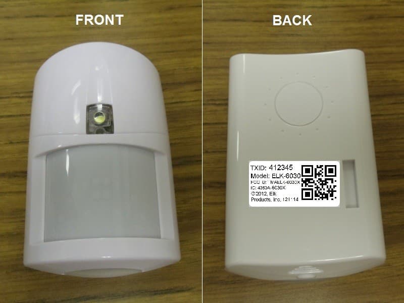
TMAELK-6030X
Mar 07, 2013PIR Sensor
Equipment Class
DXX - Part 15 Low Power Communication Device Transmitter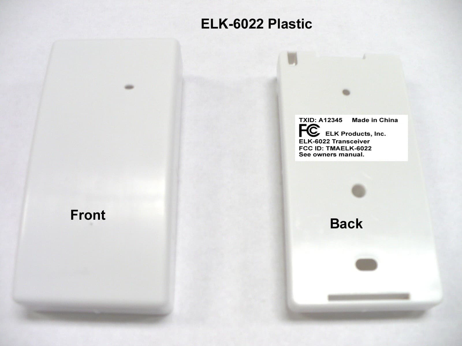
TMAELK-6022
Apr 16, 2012TRANSCEIVER
Equipment Class
DXX - Part 15 Low Power Communication Device Transmitter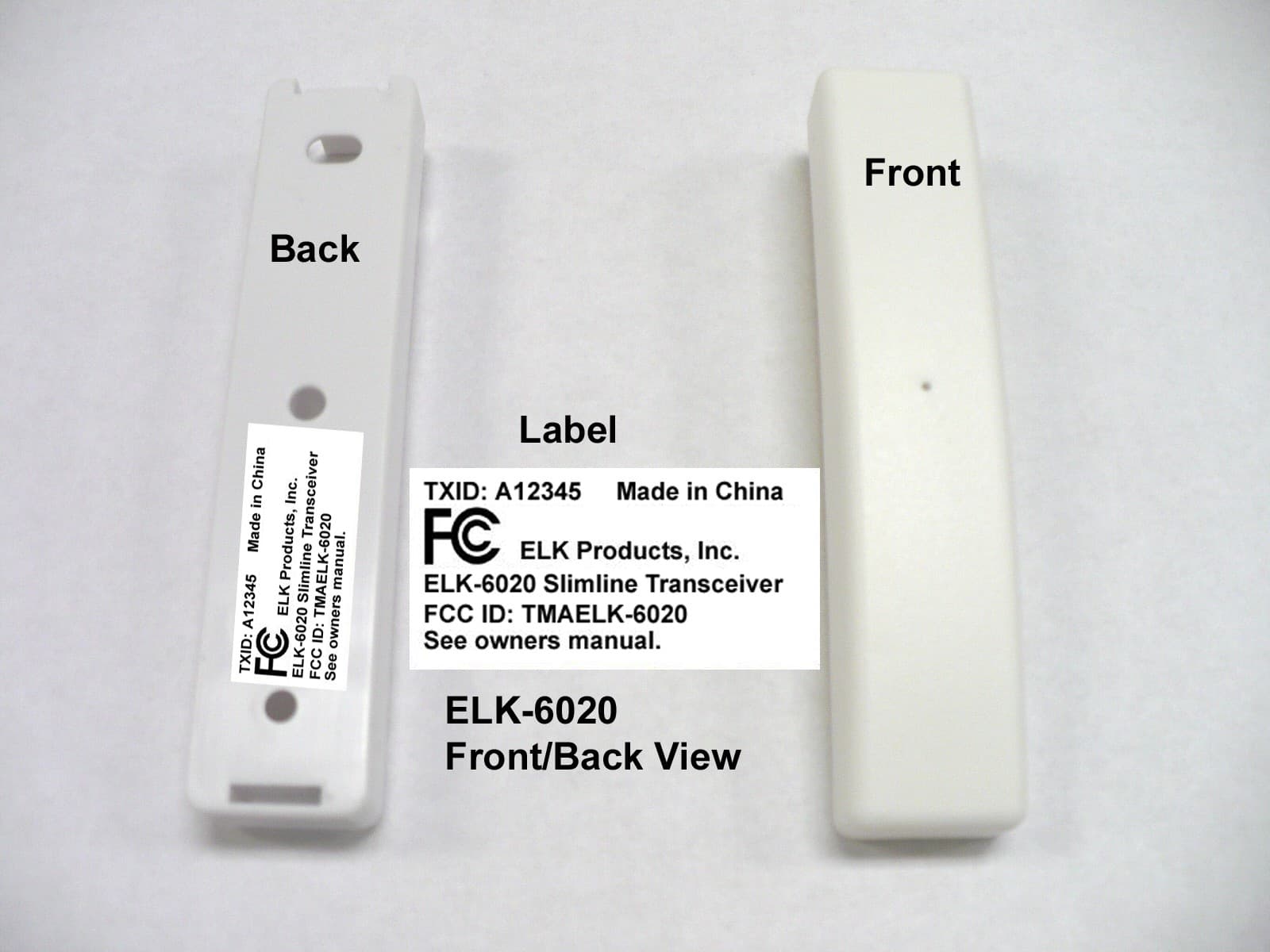
TMAELK-6020
Apr 16, 2012TRANSCEIVER
Equipment Class
DXX - Part 15 Low Power Communication Device Transmitter
TMAELK-M1XRFTW
Aug 08, 2011ELK M1 INTERFACE TRANSCEIVER
Equipment Class
DSS - Part 15 Spread Spectrum Transmitter