TMAELK-6020TRANSCEIVER
ELK Products, Inc.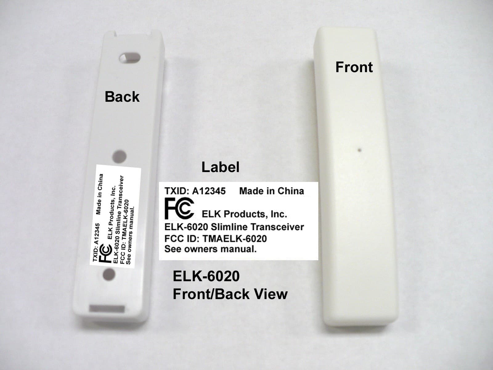
Click to zoom
Application Details
- Equipment Class
- DXX - Part 15 Low Power Communication Device Transmitter
- Date of Grant
- Apr 16, 2012
- Application Purpose
- Original Equipment
- Date of Application
- Apr 16, 2012
- Equipment Note
- TRANSCEIVER
- Frequency Range
- 902.96000000 - 926.68000000
- Company
- ELK Products, Inc.
- Country
- United States
Documents & Files

Document Text
Text extracted from the exhibit documents filed with the FCC. Open a document above to read the original.
Users Manual
ELK-6020 Wireless Slim-Line Door and Window Sensor Battery Installation and ReplacementA Low Battery signal will be reported to the Control when thesensor battery needs to be replaced.1. Remove sensor cover by grasping the sides and inserting the tip of a small flat screwdriver in the end slot. 2. Observe correct polarity when installing the new battery (see Fig 2). Be careful to not bend or damage the metalcontact leafs holding the battery.Approved Batteries: 3.6V Lithium - ER1450 3. Test sensor operation with panel. Enrolling from ElkRP Software1. Launch ElkRP and open the desired Customer Account file.2. RP requires wireless zones to be defined in groups of 16. Wireless can begin at Zone 17 (Group 2) but CANNOT gobeyond Zone 160 (Group 10). In the Folders column rightclick on > Zones (Inputs) to create a group of 16 wireless zones. Then click New Wireless Zones . Place a check mark in the box beside the desired group, then click OK.Repeat if additional wireless groups are required. NOTE: Only Zones 17 to 160 can be used for wirelesszones (max. of 144 wireless sensors). If a large numberof wireless zones are expected, AVOID conflict withexisting or future Hardwired Zones in the range of zones17 to 160 by NOT enrolling any Hardwired Zone Expanders(M1XIN) at data bus addresses 2 thru 10. 3. With ElkRP it may be more efficient to program the Zone Definitions (name, type, and options) before moving to theWireless Setup to enter the TXID and Loop number. In theFolders column click on > Wireless - Group X (the group just added), then double click one zone at a time to define aname, type, and options. Repeat for each wireless zone. 4. From the Folders column click on > Wireless Setup to enroll the wireless sensors by typing in their TXIDs. 4a. Click the > Transmitters tab, then double click a zone. 4b. Place a check mark in the Enabled box. 4c. Set Supervision type as: 0 =Non Supervised (Keyfobs), 1 =Normal “Burg” Supervision, or 2 =Fire Supervision 4d. Skip to the TXID box and enter the Sensor TXID from the label on the inside and outside of the sensor. 4e. Skip to the LOOP box and enter a 2. 4f. Click Save . Repeat the entire step 4 for each additional Wireless Sensor. FCC COMPLIANCE STATEMENT: This device complies with Part 15 of the FCC Rules. Operation is subject to the following two conditions:(1) this device may not cause harmful interference, and(2) this device must accept any interference received, including interference that may cause undesired operation.ELK-6020 Wireless Slim-Line Door & Window Sensor FCC ID: TMA ELK-6020 NOTE: ELK PRODUCTS IS NOT RESPONSIBLE FOR ANY CHANGES OR MODIFICATIONS NOT EXPRESSLY APPROVED BY THE P ARTY RESPONSIBLE FOR COMPLIANCE. SUCH MODIFICATIONS COULD VOID THE USER’S AUTHORITY TO OPERA TE THE EQUIPMENT. W ARNING + Do not reverse the battery polarity! - + Printed In USA 12/1/2011 PO Box 100 3266 US Hwy 70 WestHildebran, NC 28637Ph 828-397-4200 Fax 828-397-4415 http://www.elkproducts.com Front Page Back Page Figure 2. ELK-6020 Sensor & Backplate Operational TestingA two color LED is functional for 10 minutes after installation ofthe Battery. The LED may be re-activated for service ordiagnostics by removing and reinstalling the battery, OR byactivating the Walk Test Area menu on the M1 Keypad. NOTE: The LED may be difficult to see under direct sunlight.GOOD = GREEN blink This indicates Sensor transmitted a signal and was received and acknowledged by the Receiver. CAUTION = RED blink(s) following by a GREEN This indicates Sensor is experience difficulty reaching theReceiver. The first RED occurs after sensor has failed 4times. Each additional RED blink indicates another attempt(up to 16) to reach the receiver. After a 16 failed attemptsthe sensor will timeout and go idle for 5 minutes. A GREENblink anytime prior to 16 attempts indicates sensor was finallysuccessful. During each check-in request or supervisorycheck-in interval the sensor will update or report the currentstate of it’s input to the receiver. BAD = RED blinks with no GREEN This may indicate that either: Receiver and Sensor are out of range, Receiver isnot working, or Sensor is not transmitting. * The two color LED will remain active throughout the WalkTest process OR for 10 minutes after battery insertion and theenrollment has ended.A complete system test and Walk Test of all wireless zonesusing the prescribed M1 Keypad Menu 3 - Walktest Area feature should be performed a least once a year. MountingEnroll sensors first, then temporarily attaching them at theirintended location and walk testing PRIOR TO PERMANENTMOUNTING. It may occasionally be necessary to re-orient the sensor to improve the range and operation.Mount sensor to a flat dry surface, NOT on a curved surface asthis could damage the sensor and void the warranty. Sensorand magnet can be oriented in many directions as long as thealign marks on the sensor and magnet face each other and areclosely aligned. The maximum distance between the sensorand magnet MUST NOT exceed the specified gap. Followprescribed temperature and humidity specs. Do not use in areaswith high moisture/humidity.1. Remove sensor and magnet from their baseplates by grasping the sides and inserting the tip of a small flatscrewdriver into the end slot(s). Gently lift to separate. 2. Attach baseplates using the supplied double faced adhesive pads or #4 flathead sheet metal screws. The small raisedalignment marks on both backplates should face each otherand be aligned and the gap between MUST NOT EXCEEDthe specified operating gap. BATTERY CAUTION: Risk of fire, explosion and burns.Do not attempt to recharge or dissassemble. Do notincinerate or expose to heat above 212° F (100° C).Dispose of used batteries properly. Keep away fromchildren. Alignment Marks Maximum Operating Gap = 1/2” 1/2” Figure 1. ELK-6020 Mounting Gap and Alignment 4. If the case and back Tamper are used, remove the small rubber tamper pill from the hardware bag and insert thestem into the hollow post l…
Text truncated - open the document above for the full version.
External Photos
The status LED consists of a Red and Green LED. Upon initial powerup the status LED will operate for 10 minutes unless signaled to extend the LED operation from the M1XRFTW. A Green blip indicates the transmission was successful while a Red blip indicates the transmission required a retry with no acknowledgement. ELK-6020 Front /Back Case View With FCC Label:
ID Label/Location Info
The status LED consists of a Red and Green LED. Upon initial powerup the status LED will operate for 10 minutes unless signaled to extend the LED operation from the M1XRFTW. A Green blip indicates the transmission was successful while a Red blip indicates the transmission required a retry with no acknowledgement. ELK-6020 Front /Back Case View With FCC Label:
Internal Photos
ELK-6020 Inside PCB Top: ELK-6020 PCB Top View:
Test Report
FCC PART 15.249 TEST REPORT UNLICENSED INTENTIONAL RADIATOR Applicant ELK PRODUCTS, INC. Address 3266 HIGHWAY 70 WEST HILDEBRAN NC 28637 USA FCC ID TMAELK-6020 Product Description TRANSCEIVER Date Sample Received 12/12/2011 Date Tested 12/13/2011 Tested By Nam Nguyen Approved By Mario de Aranzeta Report Number 2913UT11TestReport.doc Test Results PASS FAIL THE ATTACHED REPORT SHALL NOT BE REPRODUCED EXCEPT IN FULL WITHOUT THE WRITTEN APPROVAL OF TIMCO ENGINEERING, INC. 849 NW State Road 45 Newberry, FL 32669 USA Ph: 888.472.2424 or 352.472.5500 Fax: 352.472.2030 Email: [email protected] Website: www.timcoengr.com Certificate # 0955-01 APPLICANT: ELK PRODUCTS, INC. FCC ID: TMAELK-6020 REPORT: E\ELK_TMA\2913UT11\2913UT11TestReport.doc Page 2 of 14 Mdea 9.20.2007 TABLE OF CONTENT GENERAL REMARKS ........................................................................................................................... 3 GENERAL INFORMATION .................................................................................................................... 4 EMC EQUIPMENT LIST........................................................................................................................ 5 TEST PROCEDURES ............................................................................................................................ 6 RADIATION INTERFERENCE ............................................................................................................... 7 OCCUPIED BANDWIDTH ..................................................................................................................... 9 BAND EDGE COMPLIANCE ............................................................................................................... 11 DUTY CYCLE ..................................................................................................................................... 13 POWER LINE CONDUCTED INTERFERENCE .................................................................................... 14 APPLICANT: ELK PRODUCTS, INC. FCC ID: TMAELK-6020 REPORT: E\ELK_TMA\2913UT11\2913UT11TestReport.doc Page 3 of 14 Mdea 9.20.2007 GENERAL REMARKS The attached report shall not be reproduced except in full without the written permission of Timco Engineering Inc. Summary The device under test does: fulfill the general approval requirements as identified in this test report not fulfill the general approval requirements as identified in this test report Attestations This equipment has been tested in accordance with the standards identified in this test report. To the best of my knowledge and belief, these tests were performed using the measurement procedures described in this report. All instrumentation and accessories used to test products for compliance to the indicated standards are calibrated regularly in accordance with ISO 17025 requirements. Certificate # 0955-01 I attest that the necessary measurements were made, under my supervision, at: Timco Engineering Inc. 849 NW State Road 45 Newberry, Fl 32669 Authorized Signatory Name: Mario de Aranzeta C.E.T. Compliance Engineer/ Lab. Supervisor Date: 12/15/2011 APPLICANT: ELK PRODUCTS, INC. FCC ID: TMAELK-6020 REPORT: E\ELK_TMA\2913UT11\2913UT11TestReport.doc Page 4 of 14 Mdea 9.20.2007 GENERAL INFORMATION DUT Specification The test results relate only to the items tested. Applicable Standard Part 15.249 DUT Description TRANSCEIVER FCC ID TMAELK-5020 Operating Frequency TX: (903 – 927) MHz RX: Same No. of Channels 25 Modulations GFSK DUT Power Source 110–120Vac/50– 60Hz DC Power Battery Operated Exclusively Test Item Prototype Pre-Production Production Type of Equipment Fixed Mobile Portable Antenna Connector FCC Rules require that the antenna connector be unique. Test Facility Timco Engineering Inc. located at 849 NW State Road 45 Newberry, FL 32669 USA. Test Conditions Temperature: 26ºC Relative humidity: 50% Test Exercise The DUT was placed in continuous transmit mode of operation. Modifications Test Supporting Equipment Supporting Device Manufacturer Model / FCC ID Serial Number N/A APPLICANT: ELK PRODUCTS, INC. FCC ID: TMAELK-6020 REPORT: E\ELK_TMA\2913UT11\2913UT11TestReport.doc Page 5 of 14 Mdea 9.20.2007 EMC EQUIPMENT LIST Device Manufacturer Model Serial Number Cal/Char Date Due Date 3-Meter Semi- Anechoic Chamber Panashield N/A N/A Listed 5/10/10 5/10/12 AC Voltmeter HP 400FL 2213A14499 CAL 6/12/11 6/12/13 Antenna: Active Loop ETS-Lindgren 6502 00062529 CAL 9/23/10 9/23/12 Frequency Counter HP 5385A 2730A03025 CAL 8/17/11 8/17/13 Hygro- Thermometer Extech 445703 0602 CAL 6/15/11 6/15/13 Modulation Analyzer HP 8901A 3435A06868 CAL 7/18/11 7/18/13 Digital Multimeter Fluke FLUKE-77 35053830 CAL 9/9/11 9/9/13 Analyzer Tan Tower Preamplifier HP 8449B-H02 3008A00372 CAL 10/28/11 10/28/13 Analyzer Tan Tower Quasi- Peak Adapter HP 85650A 3303A01690 CAL 10/28/11 10/28/13 Analyzer Tan Tower RF Preselector HP 85685A 3221A01400 CAL 10/28/11 10/28/13 Analyzer Tan Tower Spectrum Analyzer HP 8566B Opt 462 3138A07786 3144A20661 CAL 10/28/11 10/28/13 Temperature Chamber Tenney Engineering TTRC 11717-7 CHAR 4/25/10 4/25/12 Antenna ETS 3117 41534 9/22/2010 9/22/2012 Antenna Electro metrics LPA-25 1122 5/04/2011 5/04/2013 Antenna Electro metrics BIA-25 1171 1/15/2010 1/15/2012 APPLICANT: ELK PRODUCTS, INC. FCC ID: TMAELK-6020 REPORT: E\ELK_TMA\2913UT11\2913UT11TestReport.doc Page 6 of 14 Mdea 9.20.2007 TEST PROCEDURES Radiation Interference: ANSI C63.4-2003 using a spectrum analyzer, a preselector, a quasi- peak adapter, and an appropriate antenna. The analyzer was calibrated in dB above a microvolt at the output of the antenna. The resolution bandwidth was 100 kHz with an appropriate sweep speed and the video bandwidth was 300 kHz up to 1 GHz and 1 MHz with a video BW of 3 MHz above 1 GHz. When an emission was found, the table was rotated to produce the maximum signal strength. The antenna was placed in both the horizontal and vertical planes and the worse…
Text truncated - open the document above for the full version.
Contact Information
Applicant
Donald Sanders Lamb, Jr.(Sr. Engineer)
Test Firm
Timco Engineering, Inc.Bruno Clavier
Technical Specifications
| # | Rule Parts | Frequency Range | Power Output |
|---|---|---|---|
| 1 | 15C | 902.96 MHz - 926.68 MHz | - |
Other Applications from ELK Products, Inc.

TMA-ELK7TS
Dec 14, 20237 inch Color Touch Screen for Alarm Engine and Ml Controls
Equipment Class
DTS - Digital Transmission System
TMAELK-6030X
Mar 07, 2013PIR Sensor
Equipment Class
DXX - Part 15 Low Power Communication Device Transmitter
TMAELK-6022
Apr 16, 2012TRANSCEIVER
Equipment Class
DXX - Part 15 Low Power Communication Device Transmitter
TMAELK-M1XRFTW
Aug 08, 2011ELK M1 INTERFACE TRANSCEIVER
Equipment Class
DSS - Part 15 Spread Spectrum Transmitter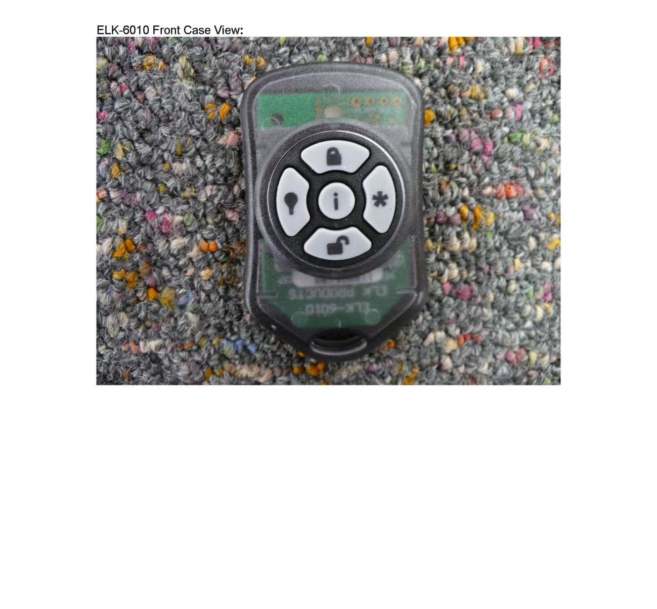
TMAELK-6010
Aug 08, 2011KEYFOB TRANSCEIVER
Equipment Class
DXX - Part 15 Low Power Communication Device Transmitter