TMAELK-6030XPIR Sensor
ELK Products, Inc.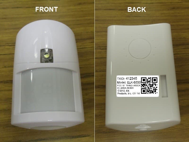
Click to zoom
Application Details
- Equipment Class
- DXX - Part 15 Low Power Communication Device Transmitter
- Date of Grant
- Mar 07, 2013
- Application Purpose
- Original Equipment
- Date of Application
- Mar 07, 2013
- Equipment Note
- PIR Sensor
- Frequency Range
- 903.00000000 - 927.00000000
- Company
- ELK Products, Inc.
- Country
- United States
Documents & Files
Document Text
Text extracted from the exhibit documents filed with the FCC. Open a document above to read the original.
Users Manual
ELK-6030 PIR Installation ManualPage 1 ELK-6030 Wireless PIR Motion Sensor For the latest downloadable version of this manual visit our website: http://www.elkproducts.com Installation and Setup Guide APPLICATION & OVERVIEW The ELK-6030 Wireless PIR Motion Sensor is designed for use with control/transceivers that accept Elk's two-way technology; such as the ELK-M1XRFTW. It is intended for use in residential and light commercial installations and incorporates many features designed to ensure its reliable performance. The dual element pyroelectric sensor in the 6030 detects movement within a specific coverage area, by sensing the infrared energy that is emitted from an intruder moving across the sensor's field of view. A change in the infrared energy creates a temperature change in the sensor's zones, which is then processed to determine if the occurrence qualifies as a legitimate motion detect event. If it does then the built-in radio will be triggered. The two-way radio (RF) in the 6030 transmits alarm, tamper, supervisory, and low battery messages to the control/receiver. Each sensor has a unique TXID number which is enrolled into the control during installation. With its two-way capability, the 6030 radio listens after every transmission for a positive acknowledgment from the control. This makes the sensor very energy efficient since it doesn't waste battery power repeating transmissions unless they are not acknowledged. Like all battery powered motion detectors, the 6030 has a mandatory sleep cycle function to help extend the battery life. After detecting motion, the sensor's radio will transmit the event to the control and wait for acknowledgment. Upon acknowledgment the sensor will enter the mandatory sleep cycle. During the sleep cycle time it cannot transmit additional events. There are two (2) time choices for the sleep cycle, both selected via DIP Switch #4. After the sleep cycle expires the sensor will once again be capable of transmitting a new event. The 6030 introduces the industry's first Security/Convenience Light. TM This high-intensity white LED projects a beam of light out in front of the sensor. It offers five (5) activation/operation modes: 1)Flash during any audible alarm activation as a visual deterent. 2)On Solid for a timed period when motion is detected and control is armed to the Away mode. (This can be disabled or modified so that it only works during certain conditions or time periods) 3)Flash on command for a timed period as a special attention grabber or general purpose indicator. 4)On Solid on command for a timed period to illuminate the immediate area (camera surveillance, etc.) 5)Quick blip in walk test mode when a coverage zone is tripped. FEATURES • Wireless two-way communication • Dual-element pyroelectric sensor • Selectable pulse count • Selectable Hi/Lo range • Excellent immunity from white light, RF, and ESD interference • Green/Red (Bi-Color) RF Acknowledge LED • White LED - Security/Convenience Light TM • Long life Lithium batteries {supplied} • Low battery trouble signal • Sleep Cycle "Battery Saver" (2 time settings) • Hourly supervision (check-in) signals • Cover tamper protection • Swivel mounting bracket included • Optional deluxe 90° swivel bracket for ceilings sold separately SPECIFICATIONS • Dimensions: 2.8"W x 4.4"H x 1.9"D • Mounting Height: 6 1/2 to 7 1/2' ft • Sensor: Dual element pyroelectric • Coverage: 39 ft x 49 ft (12m x 15m) @ 88.2° 20 dual element zones (2 Long, 10 intermediate, 4 mid, 4 short) plus look down (creep zone) • Pulse Count: 1-2 or 3-4, selectable • Sleep Time: Selectable 30 sec. or 120 sec. • RF Signal Acknowledge Indication: Green/Red (Bi-Color ) LED • Security/Convenience Light: White LED • Warm Up Period: 10 seconds • Operating Voltage: 3.0 Volts DC • Battery Type & Size: 2 x Lithium CR123A • Quiescent Current: < 10 μA • Operating Temp: 32° to +120° degrees F • Humidity: 95% RH (max.), non-condensing • Frequency: 902 - 928 Mhz channel hopping PACKAGE CONTENTS 1 - 6030 PIR electronics assembly & back housing 1 - Standard swivel bracket, locking disc, screws & anchors 1 - Blanking plug 2 - CR123A Lithium Batteries 1 - Cover locking screw UNIQUE 'INDUSTRY FIRST' SECURITY/CONVENIENCE LIGHT TM Page 2ELK-6030 PIR Installation Manual INSTALLATION 1. OPENING THE HOUSING - Remove the locking screw along the bottom (if installed). Push in the retainer tab and lift the front away from the backplate. 2. MOUNTING - To mount directly onto a wall WITHOUT the swivel bracket, start by inserting the supplied blanking plug into bracket mounting hole. This is very important! See Figure 3. Next, locate the 9 dimple marks on the inside of the backplate. Choose 2 (or more) of these for use as the screw mounting holes. Drill out the necessary holes using 1/8" bit. To prevent air or contaminants from getting into the sensor, DO NOT leave any exposed or unused holes! To mount with the supplied Swivel Bracket, start by attaching the bracket's base to the wall in the chosen location. Next, fit the backplate over the bracket and install the locking disc and small screw provided. Do not tighten this screw until the angle and direction have been adjusted as required. Sensor must be enrolled into the control using one of the following two methods. 3. SENSOR ENROLLMENT FROM KEYPAD 3.1 Make sure the M1XRFTW Transceiver is powered up and enrolled with the M1 Control. 3.2 Enter M1 Keypad Installer Programming and navigate to Menu: 14-Wireless Setup 3.3 Scroll up to sub-menu:3:Learn Sel Wireless Transmtr and press Select (right arrow). 3.4 Scroll to and select an unassigned WZone (wireless zone) and press Learn (right arrow) to enroll. 3.5 Insert the Batteries into the 6030 as soon as the keypad displays: Push Transmitter Button. The M1G will speak; “Press transmitter button for zone xx”. If successful the Keypad will chime and briefly display the 6 digit TXID code of the sensor. If a TXID is not displayed then enrollment was not success- ful. Shou…
Text truncated - open the document above for the full version.
External Photos
ELK-6030 Front/Back Housing View with FCC/IC Label: ELK-6030 Inner Shell with PCB and FCC/IC Label:
ID Label/Location Info
FCC/IC LABEL: ELK-6030 PCB Top View (Top faces away from the wall): ELK-6030 PCB Back View:
ID Label/Location Info
ELK-6030 Front/Back Housing View with FCC/IC Label: ELK-6030 Inner Shell with PCB and FCC/IC Label:
Internal Photos
FCC/IC LABEL: ELK-6030 PCB Top View (Top faces away from the wall): ELK-6030 PCB Back View:
Test Report
FCC PART 15.249 AND IC RSS-210 (i8) TEST REPORT UNLICENSED INTENTIONAL RADIATOR Applicant ELK PRODUCTS, INC. Address 3266 HIGHWAY 70 WEST HILDEBRAN NC 28637 USA FCC ID TMAELK-6030X IC 4353A-6030X Model Number ELK-6030, ELK-6030P Product Description PIR SENSOR Date Sample Received 12/19/2012 Date Tested 12/20/2012 Tested By JOHN DAY Approved By MARIO R. DE ARANZETA Report Number 3020ZAUT12TestReport.doc Test Results PASS FAIL THE ATTACHED REPORT SHALL NOT BE REPRODUCED EXCEPT IN FULL WITHOUT THE WRITTEN APPROVAL OF TIMCO ENGINEERING, INC. Testing Certificate #0955-01 849 NW State Road 45 Newberry, FL 32669 USA Ph: 888.472.2424 or 352.472.5500 Fax: 352.472.2030 Email: [email protected] Website: www.timcoengr.com APPLICANT: ELK PRODUCTS, INC. FCC ID: TMAELK-6030X IC: 4353A-6030X REPORT #: W:\E\ELK_TMA\3020ZAUT12\Extra3020ZAUT12\3020ZAUT12TestReportrev 1.doc Page 2 of 15 Mdea5.11.2012 TABLE OF CONTENT GENERAL REMARKS ................................................................................................................. 3 GENERAL INFORMATION .......................................................................................................... 4 EMC EQUIPMENT LIST .............................................................................................................. 5 TEST PROCEDURES .................................................................................................................. 6 RADIATION INTERFERENCE ..................................................................................................... 7 OCCUPIED BANDWIDTH ......................................................................................................... 10 BAND EDGE COMPLIANCE ..................................................................................................... 12 DUTY CYCLE ........................................................................................................................... 14 POWER LINE CONDUCTED INTERFERENCE ........................................................................... 15 APPLICANT: ELK PRODUCTS, INC. FCC ID: TMAELK-6030X IC: 4353A-6030X REPORT #: W:\E\ELK_TMA\3020ZAUT12\Extra3020ZAUT12\3020ZAUT12TestReportrev 1.doc Page 3 of 15 Mdea5.11.2012 GENERAL REMARKS The attached report shall not be reproduced except in full without the written permission of Timco Engineering Inc. Summary The device under test does: fulfill the general approval requirements as identified in this test report not fulfill the general approval requirements as identified in this test report Attestations This equipment has been tested in accordance with the standards identified in this test report. To the best of my knowledge and belief, these tests were performed using the measurement procedures described in this report. All instrumentation and accessories used to test products for compliance to the indicated standards are calibrated regularly in accordance with ISO 17025 requirements. Certificate # 0955-01 I attest that the necessary measurements were made, under my supervision, at: Timco Engineering Inc. 849 NW State Road 45 Newberry, Fl 32669 Authorized Signatory Name: John A. Day Testing Tech./Project Manager Date: 12/20/2012 Mario de Aranzeta, Engineer/ Lab Supervisor APPLICANT: ELK PRODUCTS, INC. FCC ID: TMAELK-6030X IC: 4353A-6030X REPORT #: W:\E\ELK_TMA\3020ZAUT12\Extra3020ZAUT12\3020ZAUT12TestReportrev 1.doc Page 4 of 15 Mdea5.11.2012 GENERAL INFORMATION DUT Specification The test results relate only to the items tested. Applicable Standard Part 15.249, RSS-210 (issue 8) DUT Description PIR SENSOR FCC ID TMAELK-6030 IC 4353A-6030X Model Number ELK-6030, ELK-6030P Operating Frequency TX: 902 – 928 MHz RX: Same No. of Channels 25 DUT Power Source 110–120Vac/50– 60Hz DC Power Battery Operated Exclusively Test Item Prototype Pre-Production Production Type of Equipment Fixed Mobile Portable Antenna Connector FCC Rules require that the antenna connector be unique. Test Facility Timco Engineering Inc. located at 849 NW State Road 45 Newberry, FL 32669 USA. Test Conditions Temperature: 26ºC Relative humidity: 50% Test Exercise The DUT was placed in continuous transmit mode of operation. Modifications Test Supporting Equipment Supporting Device Manufacturer Model / FCC ID Serial Number N/A APPLICANT: ELK PRODUCTS, INC. FCC ID: TMAELK-6030X IC: 4353A-6030X REPORT #: W:\E\ELK_TMA\3020ZAUT12\Extra3020ZAUT12\3020ZAUT12TestReportrev 1.doc Page 5 of 15 Mdea5.11.2012 EMC EQUIPMENT LIST Device Manufacturer Model Serial Number Cal/Char Date Due Date 3/10-Meter OATS TEI N/A N/A 12/31/11 12/31/13 3-Meter OATS TEI N/A N/A 12/31/11 12/31/13 Antenna: Passive Loop EMC Test Systems EMCO 6512 9706-1211 06/14/12 06/14/14 Frequency Counter HP 5385A 2730A03025 08/17/11 08/17/13 Frequency Counter HP 5352B 2632A00165 06/22/11 06/22/13 Digital Multimeter Fluke 77 43850817 02/22/12 02/22/13 Antenna: Active Loop ETS-Lindgren 6502 00062529 09/23/10 09/23/13 Antenna: Double-Ridged Horn Electro-Metrics RGA-180 2319 06/19/12 06/19/14 LISN Electro-Metrics ANS-25/2 2604 10/28/11 10/28/13 DC Power Supply HP 6264B 03/21/11 03/21/13 3-Meter Semi- Anechoic Chamber Panashield N/A N/A 12/31/11 12/31/13 Temperature Chamber Tenney Engineering TTRC 11717-7 07/03/12 07/03/14 Antenna: Biconnical Electro-Metrics BIA-25 1171 06/13/12 06/13/14 Antenna: Log- Periodic Electro-Metrics LPA-25 1122 05/04/11 05/04/13 Digital Multimeter Fluke 77 35053830 09/09/11 09/09/13 Antenna: Biconnical Eaton 94455-1 1096 05/04/11 05/04/13 Analyzer Tan Tower Preamplifier HP 8449B-H02 3008A00372 11/21/09 10/28/13 Analyzer Tan Tower Quasi- Peak Adapter HP 85650A 3303A01690 11/22/09 10/28/13 Analyzer Tan Tower RF Preselector HP 85685A 3221A01400 11/21/09 10/28/13 Analyzer Tan Tower Spectrum Analyzer HP 8566B Opt 462 3138A07786 3144A20661 11/24/09 10/28/13 Horn Antenna ETS-Lindgren 3117 35923 12/20/11 12/20/13 Antenna: Log- Periodic Eaton 96005 1243 05/31/11 05/31/13 APPLICANT: ELK PRODUCTS, INC. FCC ID: TMAELK-6030X IC: 4…
Text truncated - open the document above for the full version.
Contact Information
Applicant
Donald Sanders Lamb, Jr.(Sr. Engineer)
Test Firm
Timco Engineering, Inc.Bruno Clavier
Technical Specifications
| # | Rule Parts | Frequency Range | Power Output |
|---|---|---|---|
| 1 | 15C | 903 MHz - 927 MHz | - |
Other Applications from ELK Products, Inc.

TMA-ELK7TS
Dec 14, 20237 inch Color Touch Screen for Alarm Engine and Ml Controls
Equipment Class
DTS - Digital Transmission System
TMAELK-6022
Apr 16, 2012TRANSCEIVER
Equipment Class
DXX - Part 15 Low Power Communication Device Transmitter
TMAELK-6020
Apr 16, 2012TRANSCEIVER
Equipment Class
DXX - Part 15 Low Power Communication Device Transmitter
TMAELK-M1XRFTW
Aug 08, 2011ELK M1 INTERFACE TRANSCEIVER
Equipment Class
DSS - Part 15 Spread Spectrum Transmitter
TMAELK-6010
Aug 08, 2011KEYFOB TRANSCEIVER
Equipment Class
DXX - Part 15 Low Power Communication Device Transmitter