TS8ILP0001FIDEAL LIFE POD
3J Tech. Co., Ltd.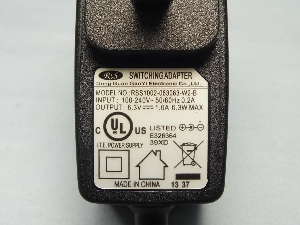
Click to zoom
Application Details
- Equipment Class
- PCB - PCS Licensed Transmitter
- Date of Grant
- Jan 05, 2016
- Application Purpose
- Original Equipment
- Date of Application
- Jan 04, 2016
- Equipment Note
- IDEAL LIFE POD
- Frequency Range
- 1852.40000000 - 1907.60000000
- Company
- 3J Tech. Co., Ltd.
- Country
- Taiwan
Documents & Files
Document Text
Text extracted from the exhibit documents filed with the FCC. Open a document above to read the original.
Users Manual
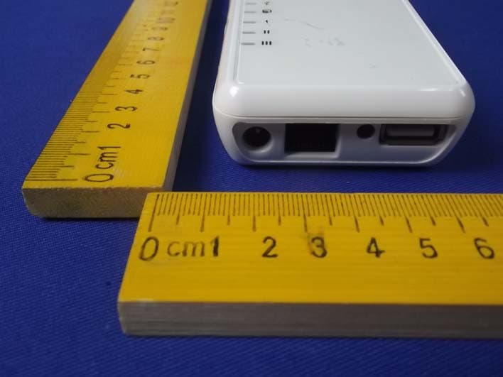
IDEAL LIFE Pod ™ Communication Gateway (Access Point) Model ILP0001 Products may vary from images shown NOTE: The system is intended for information purposes only, for expert advice make sure to consult a healthcare professional. Any instructions for change in treatment and health related information or advice should only be made directly with a healthcare professional. For use with devices from the IDEAL LIFE Health Management System ™ INSTRUCTION MANUAL Read before use 08 LP0001 CellPod manual v7.0 Jan 2015 208 LP0001 CellPod manual v7.0 Jan 2015 Table of Contents TABLE OF CONTENTS.....................2 INTRODUCTION...............................3 PACKAGE CONTENTS.....................4 LOCATION/INTERFERENCE...........5 Your IDEAL LIFE Pod™......................6 Table of Contents Connecting Your IDEAL LIFE Cellular Pod™........................................7 SPECIFICATIONS .................................8 FCC STATEMENT..................................9 SERVICE REQUIREMENTS................10 3 Introduction Preface Thank you for purchasing the IDEAL LIFE Cellular Pod™, also called ILP 0001. This is an optional product that is used together with your other IDEAL LIFE products. The Pod allows you to automatically send and record information, to help you better manage your health with your health care provider. After readings are taken, they are stored and the Pod transmits them so that they can be viewed online as graphs and tables. CAUTION: Before using this product, read all instructions thoroughly. For any questions or comments, please call IDEAL LIFE customer service toll-free at 1-866-IDEAL-41 (1-866-433-2541). Introduction 08 LP0001 CellPod manual v7.0 Jan 2015 4 08 LP0001 CellPod manual v7.0 Jan 2015 Package Contents Your System includes: Package Contents ILP 0001 IDEAL LIFE Cellular POD™ AC ADAPTER INSTRUCTION MANUAL RJ45 CABLE ------------------------------------------------------------------------------------------------------------------------------------- Optional Accessory (may be included) 5 Location/Interference The IDEAL LIFE Cellular Pod™ uses wireless radio waves to transfer information from your IDEAL LIFE Manager™. For the best distance and least interference, the recommended IDEAL LIFE Cellular Pod™ location is: •Away from electrical appliances such as a TV, personal computer or a cordless phone • In a HIGH and CENTRAL location with no obstructions such as walls IDEAL LIFE Cellular Pod™ Location/Interference 08 LP0001 CellPod manual v7.0 Jan 2015 608 LP0001 CellPod manual v7.0 Jan 2015 Your IDEAL LIFE Pod ™ Your IDEAL LIFE Cellular Pod ™ USB Port (not used) LED Display Internet Cable RJ45 Jack Antenna attachment AC adapter jack 7 Connecting Your IDEAL LIFE Cellular Pod ™ USING CELLULAR INTERNET Information may be transmitted using cellular Internet. Make sure Pod is Powered On. To do this, simply connect the small end of the power supply into the power AC jack on the back of the IDEAL LIFE Cellular Pod™ marked POWER. Plug the other end into an AC power outlet. Your IDEAL LIFE Cellular Pod™will automatically power up once it is plugged in to an AC power outlet. Information from the IDEAL LIFE Manager™ will automatically be uploaded to the IDEAL LIFE website. USING AN RJ45 JACK Another way to transmit information is using the Ethernet cord and the RJ45 jack. To do this, plug one end of the Ethernet cord into a modular RJ45 wall jack. Plug the other end of the Ethernet cord into the RJ45 jack on the back of your IDEAL LIFE Pod™. Connect the small end of the power supply into the power AC jack on the back of the IDEAL LIFE Pod™marked POWER. Plug the other end into an AC power outlet. Your IDEAL LIFE Cellular Pod™ will automatically power up once it is plugged in to an AC power outlet. Connecting Your IDEAL LIFE Cellular Pod™ 08 LP0001 CellPod manual v7.0 Jan 2015 808 LP0001 CellPod manual v7.0 Jan 2015 IDEAL LIFE Cellular Pod ™ Model: ILP 0001 IDEAL LIFE Cellular Pod™ Connectivity: USB and Ethernet Antenna: External Operating System: Linux Display: 4 LEDs + 4 Signal Strength Bars Power Source: Class 2 Power Adapter 6.3V 1A Operating Temperature/Humidity: 32 F - 131 F / Below 85% relative humidity Storage temperature/Humidity: 0F - 185F / Below 90% relative humidity Console weight: 5.11 oz Outer dimensions: Approx. 4.72” Width x 1.32” Height x 4.29” Depth Note: 9 FCC Statement FCC Statement 08 LP0001 CellPod manual v7.0 Jan 2015 This device complies with Part 15 of the FCC Rules. Operation is subject to the following two conditions: (1) This device may not cause harmful interference, and (2) this device must accept any interference received, including interference that may cause undesired operation. This equipment has been tested and found to comply with the limits for a Class B digital device, pursuant to Part 15 of the FCC Rules. These limits are designed to provide reasonable protection against harmful interference in a residential installation. This equipment generates, uses and can radiate radio frequency energy and, if not installed and used in accordance with the instructions, may cause harmful interference to radio communications. However, there is no guarantee that interference will not occur in a particular installation. If this equipment does cause harmful interference to radio or television reception, which can be determined by turning the equipment off and on, the user is encouraged to try to correct the interference by one of the following measures: - Reorient or relocate the receiving antenna. - Increase the separation between the equipment and receiver. - Connect the equipment into an outlet on a circuit different from that to which the receiver is connected. - Consult the dealer or an experienced radio/TV technician for help. FCC Caution: - Any changes or modifications not expressly approved by the party responsible for compliance could void the user's authority to operate this equipment. - This transmitter must not be co-located or operating in conjun…
Text truncated - open the document above for the full version.
External Photos
Page 1 CONSTRUCTION PHOTOS OF EUT Page 2 Page 3 Page 4 Page 5
ID Label/Location Info
Back Cover of EUT FCC ID: TS8ILP0001F
Internal Photos
Page 6 Page 7 Page 8 Page 9 Page 10
RF Exposure Info
FCC MPE Evaluation Report Report Format Version 5.0.0 Page No. : 1 of 8 Report No. : SA150629C15A Issued Date : Nov. 19, 2015 Reference No.: 150630C15 FCC MPE Evaluation Report Report No. : SA150629C15A Applicant : 3J Tech. Co., Ltd. Address : 2F, No.342 Fushing N Rd. Taipei, Taiwan Product : IDEAL LIFE POD FCC ID : TS8ILP0001F Brand : IDEAL LIFE Model No. : ILP0001F Standards : FCC Part 2 (Section 2.1091) KDB 447498 D01 Sample Received Date : Jun. 30, 2015 Date of Evaluation : Jul. 07, 2015 CERTIFICATION: The above equipment have been tested by Bureau Veritas Consumer Products Services (H.K.) Ltd., Taoyuan Branch – Lin Kou Laboratories, and found compliance with the requirement of the above standards. The test record, data evaluation & Equipment Under Test (EUT) configurations represented herein are true and accurate accounts of the measurements of the sample’s SAR characteristics under the conditions specified in this report. It should not be reproduced except in full, without the written approval of our laboratory. The client should not use it to claim product certification, approval, or endorsement by TAF or any government agencies. Prepared By : Evonne Liu / Specialist Approved By : Gordon Lin / Assistant Manager This report is for your exclusive use. Any copying or replication of this report to or for any other person or entity, or use of our name or trademark, is permitted only with our prior written permission. This report sets forth our findings solely with respect to the test samples identified herein. The results set forth in this report are not indicative or representative of the quality or characteristics of the lot from which a test sample was taken or any similar or identical product unless specifically and expressly noted. Our report includes all of the tests requested by you and the results thereof based upon the information that you provided to us. You have 60 days from date of issuance of this report to notify us of any material error or omission caused by our negligence, provided, however, that such notice shall be in writing and shall specifically address the issue you wish to raise. A failure to raise such issue within the prescribed time shall constitute your unqualified acceptance of the completeness of this report, the tests conducted and the correctness of the report contents. Unless specific mention, the uncertainty of measurement has been explicitly taken into account to declare the compliance or non-compliance to the specification. FCC MPE Evaluation Report Report Format Version 5.0.0 Page No. : 2 of 8 Report No. : SA150629C15A Issued Date : Nov. 19, 2015 Reference No.: 150630C15 Table of Contents Release Control Record ............................................................................................................................................................... 3 1. Description of Equipment Under Test ................................................................................................................................. 4 2. MPE (Maximum Permissible Exposure) Assessment ......................................................................................................... 5 2.1 Introduction .................................................................................................................................................................. 5 2.2 RF Radiation Exposure Limits ...................................................................................................................................... 5 2.3 MPE Assessment Method ............................................................................................................................................ 6 2.4 MPE Calculation for Standalone Operations ................................................................................................................ 6 2.5 MPE Calculation for Simultaneous Transmission Operations ...................................................................................... 7 3. Information on the Testing Laboratories ............................................................................................................................. 8 FCC MPE Evaluation Report Report Format Version 5.0.0 Page No. : 3 of 8 Report No. : SA150629C15A Issued Date : Nov. 19, 2015 Reference No.: 150630C15 Release Control Record Report No. Reason for Change Date Issued SA150629C15A Initial release Nov. 19, 2015 FCC MPE Evaluation Report Report Format Version 5.0.0 Page No. : 4 of 8 Report No. : SA150629C15A Issued Date : Nov. 19, 2015 Reference No.: 150630C15 1. Description of Equipment Under Test EUT Type IDEAL LIFE POD FCC ID TS8ILP0001F Brand Name IDEAL LIFE Model Name ILP0001F Tx Frequency Bands (Unit: MHz) GSM850 : 824.2 ~ 848.8 GSM1900 : 1850.2 ~ 1909.8 WCDMA Band II : 1852.4 ~ 1907.6 WCDMA Band V : 826.4 ~ 846.6 Bluetooth : 2402 ~ 2480 Uplink Modulations GSM & GPRS : GMSK EDGE : 8PSK WCDMA : QPSK Bluetooth : GFSK, π/4-DQPSK, 8-DPSK Antenna Type Fixed External Antenna EUT Stage Identical Prototype Note: 1. The above EUT information is declared by manufacturer and for more detailed features description please refers to the manufacturer's specifications or User's Manual. List of Accessory: AC Adapter Brand Name Dongguan Gaoyi Electronic Co., Ltd. Model Name RSS1002-063063-W2-B Power Rating I/P:100-240Vac, 50/60Hz, 0.2A; O/P: 6.3Vdc, 1.0A FCC MPE Evaluation Report Report Format Version 5.0.0 Page No. : 5 of 8 Report No. : SA150629C15A Issued Date : Nov. 19, 2015 Reference No.: 150630C15 2. MPE (Maximum Permissible Exposure) Assessment 2.1 Introduction According to 47 CFR §2.1091, a mobile device is defined as a transmitting device designed to be used in other than fixed locations and to generally be used in such a way that a separation distance of at least 20 cm is normally maintained between the transmitting antenna and the body of the user or nearby persons. In this context, the term “fixed location” means that the device is phy…
Text truncated - open the document above for the full version.
Test Report
Report No.: RF150629C15 Page No. 1 / 32 Report Format Version: 6.1.1 FCC Test Report (PART 22) Report No.: RF150629C15 FCC ID: TS8ILP0001F Test Model: ILP0001F Received Date: Jun. 29, 2015 Test Date: Jul. 01, 2015 ~ Jul. 07, 2015 Issued Date: Nov. 13, 2015 Applicant: 3J Tech. Co., Ltd. Address: 2F, No.342 Fushing N Rd. Taipei, Taiwan Issued By: Bureau Veritas Consumer Products Services (H.K.) Ltd., Taoyuan Branch Lab Address: No. 47-2, 14th Ling, Chia Pau Vil., Lin Kou Dist., New Taipei City, Taiwan ( R.O.C ) Test Location: No. 19, Hwa Ya 2nd Rd, Wen Hwa Tsuen, Kwei Shan Hsiang, Taoyuan Hsien 333, Taiwan, R.O.C. This report is for your exclusive use. Any copying or replication of this report to or for any other person or entity, or use of our name or trademark, is permitted only with our prior written permission. This report sets forth our findings solely with respect to the test samples identified herein. The results set forth in this report are not indicative or representative of the quality or characteristics of the lot from which a test sample was taken or any similar or identical product unless specifically and expressly noted. Our report includes all of the tests requested by you and the results thereof based upon the information that you provided to us. You have 60 days from date of issuance of this report to notify us of any material error or omission caused by our negligence, provided, however, that such notice shall be in writing and shall specifically address the issue you wish to raise. A failure to raise such issue within the prescribed time shall constitute your unqualified acceptance of the completeness of this report, the tests conducted and the correctness of the report contents. Unless specific mention, the uncertainty of measurement has been explicitly taken into account to declare the compliance or non-compliance to the specification. The report must not be used by the client to claim product certification, approval, or endorsement by TAF or any government agencies Report No.: RF150629C15 Page No. 2 / 32 Report Format Version: 6.1.1 Table of Contents Release Control Record .................................................................................................................................. 3 1 Certificate of Conformity ........................................................................................................................... 4 2 Summary of Test Results ........................................................................................................................... 5 2.1 Measurement Uncertainty ..................................................................................................................... 5 2.2 Test Site and Instruments ..................................................................................................................... 6 3 General Information ................................................................................................................................... 7 3.1 General Description of EUT .................................................................................................................. 7 3.2 Configuration of System Under Test ..................................................................................................... 8 3.2.1 Description of Support Units ....................................................................................................... 8 3.3 Test Mode Applicability and Tested Channel Detail .............................................................................. 9 3.4 EUT Operating Conditions .................................................................................................................. 10 3.5 General Description of Applied Standards .......................................................................................... 10 4 Test Types and Results ............................................................................................................................. 11 4.1 Output Power Measurement ................................................................................................................ 11 4.1.1 Limits of Output Power Measurement ....................................................................................... 11 4.1.2 Test Procedures ......................................................................................................................... 11 4.1.3 Test Setup ................................................................................................................................. 12 4.1.4 Test Results .............................................................................................................................. 13 4.2 Frequency Stability Measurement ...................................................................................................... 15 4.2.1 Limits of Frequency Stabiliity Measurement ............................................................................. 15 4.2.2 Test Procedure ......................................................................................................................... 15 4.2.3 Test Setup ................................................................................................................................. 15 4.2.4 Test Results .............................................................................................................................. 16 4.3 Occupied Bandwidth Measurement .................................................................................................... 17 4.3.1 Test Procedure ......................................................................................................................... 17 4.3.2 Test Setup ................................................................................................................................. 17 4.3.3 Test Result .............................................................................…
Text truncated - open the document above for the full version.
Test Report
Report No.: RF150629C15-1 Page No. 1 / 32 Report Format Version: 6.1.1 FCC Test Report (PART 24) Report No.: RF150629C15-1 FCC ID: TS8ILP0001F Test Model: ILP0001F Received Date: Jun. 29, 2015 Test Date: Jul. 01, 2015 ~ Jul. 03, 2015 Issued Date: Nov. 13, 2015 Applicant: 3J Tech. Co., Ltd. Address: 2F, No.342 Fushing N Rd. Taipei, Taiwan Issued By: Bureau Veritas Consumer Products Services (H.K.) Ltd., Taoyuan Branch Lab Address: No. 47-2, 14th Ling, Chia Pau Vil., Lin Kou Dist., New Taipei City, Taiwan ( R.O.C ) Test Location: No. 19, Hwa Ya 2nd Rd, Wen Hwa Tsuen, Kwei Shan Hsiang, Taoyuan Hsien 333, Taiwan, R.O.C. This report is for your exclusive use. Any copying or replication of this report to or for any other person or entity, or use of our name or trademark, is permitted only with our prior written permission. This report sets forth our findings solely with respect to the test samples identified herein. The results set forth in this report are not indicative or representative of the quality or characteristics of the lot from which a test sample was taken or any similar or identical product unless specifically and expressly noted. Our report includes all of the tests requested by you and the results thereof based upon the information that you provided to us. You have 60 days from date of issuance of this report to notify us of any material error or omission caused by our negligence, provided, however, that such notice shall be in writing and shall specifically address the issue you wish to raise. A failure to raise such issue within the prescribed time shall constitute your unqualified acceptance of the completeness of this report, the tests conducted and the correctness of the report contents. Unless specific mention, the uncertainty of measurement has been explicitly taken into account to declare the compliance or non-compliance to the specification. The report must not be used by the client to claim product certification, approval, or endorsement by TAF or any government agencies. Report No.: RF150629C15-1 Page No. 2 / 32 Report Format Version: 6.1.1 Table of Contents Release Control Record .................................................................................................................................. 3 1 Certificate of Conformity ........................................................................................................................... 4 2 Summary of Test Results ........................................................................................................................... 5 2.1 Measurement Uncertainty ..................................................................................................................... 5 2.2 Test Site and Instruments ..................................................................................................................... 6 3 General Information ................................................................................................................................... 7 3.1 General Description of EUT .................................................................................................................. 7 3.2 Configuration Of System Under Test .................................................................................................... 8 3.2.1 Description of Support Units ....................................................................................................... 8 3.3 Test Mode Applicability and Tested Channel Detail .............................................................................. 9 3.4 EUT Operating Conditions .................................................................................................................. 10 3.5 General Description of Applied Standards .......................................................................................... 10 4 Test Types and Results ............................................................................................................................. 11 4.1 Output Power Measurement ................................................................................................................ 11 4.1.1 Limits of Output Power Measurement ....................................................................................... 11 4.1.2 Test Procedures ......................................................................................................................... 11 4.1.3 Test Setup ................................................................................................................................. 12 4.1.4 Test Results .............................................................................................................................. 13 4.2 Frequency Stability Measurement ...................................................................................................... 15 4.2.1 Limits of Frequency Stabiliity Measurement ............................................................................. 15 4.2.2 Test Procedure ......................................................................................................................... 15 4.2.3 Test Setup ................................................................................................................................. 15 4.2.4 Test Results .............................................................................................................................. 16 4.3 Occupied Bandwidth Measurement .................................................................................................... 17 4.3.1 Test Procedure ......................................................................................................................... 17 4.3.2 Test Setup ................................................................................................................................. 17 4.3.3 Test Result .......................................................................…
Text truncated - open the document above for the full version.
Test Setup Photos
1 PHOTOGRAPHS OF THE TEST CONFIGURATION
Contact Information
Applicant
Kiwi Huang(Vice President)
Technical Contact
Bureau Veritas Consumer Products ServicesKwei shan Hsiang
[email protected]886 3 318-3232
No.19, Hwa Ya 2nd Rd, Wen Hwa Tsuen, · Taiwan
Non-Technical Contact
Bureau Veritas Consumer Products ServicesKwei shan Hsiang
[email protected]886 3 318-3232
Test Firm
Bureau Veritas CPS(H.K.) Ltd., Taoyuan BranchRichard Chen
Technical Specifications
| # | Rule Parts | Frequency Range | Power Output | Emission | Tolerance |
|---|---|---|---|---|---|
| 4 | 24E | 1.85 GHz - 1.91 GHz | 114.00 mW | 4M16F9W | 0.002 ppm |
Other Applications from 3J Tech. Co., Ltd.
TS8SMIII
Jun 11, 2014Super Modem III
Equipment Class
DTS - Digital Transmission System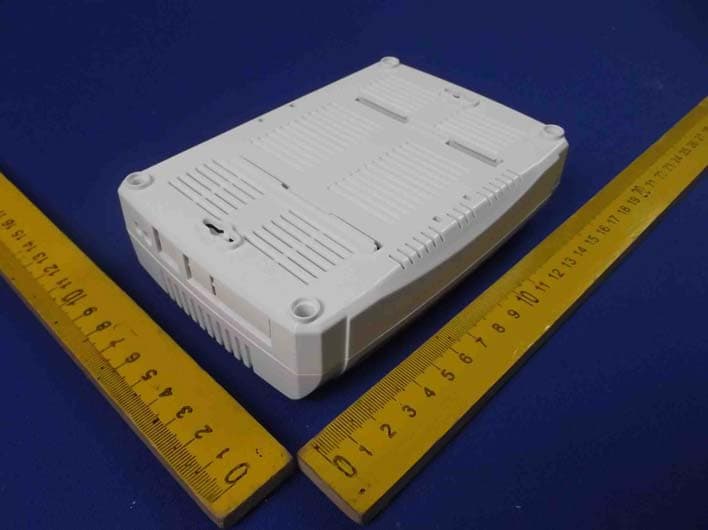
TS8G2WIFIIII
Jun 08, 2014WiFi Router
Equipment Class
DTS - Digital Transmission System
TS8ILP0001A
Dec 20, 2009IDEAL LIFE POD
Equipment Class
DSS - Part 15 Spread Spectrum Transmitter
TS8ILP0001
Apr 01, 2007IDEAL LIFE POD
Equipment Class
DSS - Part 15 Spread Spectrum Transmitter
TS8BTMODEM
Dec 13, 2005BLUETOOTH MODEM
Equipment Class
DSS - Part 15 Spread Spectrum Transmitter