TSDNMD-AM01Digital R/C control system
Nomadio, Inc.
Click to zoom
Application Details
- Equipment Class
- DTS - Digital Transmission System
- Date of Grant
- Nov 06, 2005
- Application Purpose
- Original Equipment
- Date of Application
- Nov 06, 2005
- Equipment Note
- Digital R/C control system
- Frequency Range
- 2402.00000000 - 2479.00000000
- Company
- Nomadio, Inc.
- Country
- United States
Documents & Files
Document Text
Text extracted from the exhibit documents filed with the FCC. Open a document above to read the original.
Users Manual
USERS GUIDE Version 1.0.2 Published July 2005 Sensor Quick Reference D ispla y Sc reen Antenna Spea ker Throttle Trigger Headphone & PC Connections Steering Trim Shift Buttons Battery C ompart ment / R eceiv er Program ming Cable St eering W heel D ispla y Sc reen Navigation Controls ( T1) Throt t le D ual Rate Trim ( T2) St eering D ual Rate Trim (T3) Throttle Trim (TR) Steering Trim (TL) Steering Trim Menu Button On/Off S witch Selection Buttons Transceiver Quick Reference Receptacle for: Car Battery Sensor Receptacles for: RX Battery (po wer) Steering (Ch1) Throttle (Ch2) Shift Servo (Ch3) Receptacle for: Digital Sensor (e.g., RPM/Speed ) /Receiver Programming Cable BIND button (recessed) Indicator LED Receptacle for: Analog Sensor s (e.g., Temp) Sensor Quick Reference.................................. II Transceiver Quick Reference.........................III Statement of Complia nce ................................ 2 Getting t o k now your Sensor........................... 3 Power Sw itch...................................................... 3 Display Screen.................................................... 3 Menu Button....................................................... 3 Navigation Buttons............................................... 3 Selection Buttons................................................. 4 Trim Buttons....................................................... 4 Grip Buttons....................................................... 4 Connection Ports................................................. 4 Charging and Instal ling Batteries ................... 5 Charging the Supplied NiMH Batteries...................... 5 Installing the Batteries.......................................... 5 A djusting the Screen........................................ 6 Converting for Left Handed Use ...................... 7 Installing the T ransceiver................................ 9 Mounting the Transceiv er...................................... 9 Connecting the Transceiver.................................... 9 Installing the Sensors.................................... 10 Receiver Battery Sensor...................................... 10 Voltage Sensor.................................................. 10 Temperature Sensor........................................... 10 Connecting the Temperature Sensor...................... 11 Binding t he T ransceiver................................. 12 How the Binding Process Works............................ 12 Binding y our transceiver the first time.................... 14 Sensor Controls .............................................. 15 Top Menu Lev el................................................. 16 Steering F unctions............................................. 16 Throttle F unctions.............................................. 30 Shift Servo F unctions.......................................... 46 Model Management............................................ 56 Controller Setup................................................ 60 Failsafes.......................................................... 64 Sensor Digital RC Desk top............................. 66 Minimum Sy stem Requirements............................ 66 Installing the RC Desktop.................................... 66 Connecting the Sensor to your C omputer................ 73 Using the Sensor Digital RC Desktop...................... 73 Registration...................................................... 74 Receiv ing Settings F rom the Sensor....................... 76 Editing Settings................................................. 77 Saving Settings................................................. 77 Sending Settings to the Sensor............................. 78 Installing S ensor F irmw are.................................. 78 Specificatio ns ................................................. 79 Sensor Controller............................................... 79 Transceiver ...................................................... 79 Support ........................................................... 80 Noma dio 3 Year Limited Warranty................ 81 Warranty C overage............................................ 81 Exclusions and Limitations................................... 81 Statement of Compliance FCC Compliance St at ement This equipment has been tested and found to comply with the limits for a Class B digital device, pursuant to Part 15 of the F CC Rules. These li mi ts are de signed to prov ide reasonable protection against harmful interference in a residential installation. This equipment generates, uses and can radiate radio frequency energy and, if not installed and used in accordance with the instructions, may cause harmful interference to radio communications. Howev er, there is no guarantee that interference will not occur in a particular installation. If this equipment does cause harmful interference to radio or telev ision reception, which can be determined by turning the equipment off and on, the user is encouraged to try to correct the interference by one or more of the following measures: – Reorient or relocate the receiv ing antenna. – Increase the separation between the equipment and receiv er. – C onnect the equipment into an outlet on a circuit different from that to which the receiv er is connected. – Consult the dealer or an experienced technician for help. • This dev ice co mplies w ith P art 15 o f the F CC Rules and w ith RSS-210 o f Industry C anada. O peration is subject to the following two conditions: 1) this device my not cause harmful interference, and 2) this device must accept any interference received, including interference that may cause undesired operation. • The users manual or instruction manual for an intentional or unintentional radiator shall caution the user that changes or modifications not expressly approv ed by the party responsible for compliance could v oid the user's authority to operate the equipment. Warning: Changes or mo…
Text truncated - open the document above for the full version.
Users Manual
PREMIUM DIGITAL R/C CONTROL SYSTEM SPECIFICATIONS ControllerRadio Type: digital spread spectrum 2.4Ghz Radio Mode: direct sequence spread spectrum Range: 1000ft. Power Output: 75mW Frame Rate: 100 frames per second Latency: 10 millisecond max, 5ms typical Dimensions: 300mm x 139mm x 125mm (HWD) Weight (w/Batteries): 674g Servo Channels: 4 Rechargeable Batteries: NiMH (included) Charger: included Model Memory: 8 named, custom graphics and sound Controller Batt. Voltage Monitor: graphic and real-time Car Batt. Voltage Monitor: graphic and real-time Timers: operation and lap timers Trims: adjustable trims and sub-trims Controls: dual rate, endpoints, exponential, mixing and servo speed adjust on all channels Anti-Lock: brake anti-lock with cycle, delay and depth Idle Up: yes Speaker: .75” w/headphone jack Audio: programmable WAV file audio and tones Tactile Alarm: programmable vibrator Display: movable backlit monochrome LCD Resolution: 128 x 64 pixels Auto Modes: auto display and display only Presets: failsafe and auto start Telemetry: 3 channels of real time telemetry Telemetry Sensors: speed, temperature and battery Servos Supported: any combination of analog and digital Left-Handed Operation: yes (user modified) PC Connectivity: USB serial for customization, analysis and updates Antenna: fixed 3” antenna Architecture: software upgradable Transceiver Dimensions: 47.7mm x 30.2mm x 19mm Weight: 34g (including antenna) Antenna length: 22.8cm Antenna thickness: 1.8mm DEALER STAMP Nomadio was formed in 2002 to develop and deliver a new level of secure and robust remote control and telemetry systems for unmanned vehicles. The company has been the recipient of numerous public and private grants and awards based on the promise of its technolgy. Nomadio’s products are used by several branches of the U.S. armed forces. Nomadio’s products are proudly designed, manufactured and supported in the U.S.A. ©2005 NOMADIO • 2.4Ghz Digital Spread Spectrum (DSS) radio• 100Hz frame rate for super-fast response• Fully digital path from your hands to your servos• Ultra-high resolution driving controls• Fully integrated real-time telemetry from your car• Heads-up competition driving system with real-time driver alerts • Programmable alerts include customized screens, sounds and vibration• Large backlit movable graphic display• Ergonomic design reduces hand and arm fatigue• Connects to your PC for easy programming and customization• PC software includes hundreds of sounds, graphics, setups and tools • ROAR approved• Three year limited warranty• Designed and manufactured in the U.S.A. ...A complete redesign of the R/C Controller using today’s state-of-the-art technology: REAL-TIME TELEMETRYR E A L - T I M E T E L E M E T R Y HEADS-UP COMPETITION H E A D S - U P C O M P E T I T I O N DRIVING SYSTEMD R I V I N G S Y S T E M NO MORE CRYSTAL RADIOS N O M O R E C R Y S T A L R A D I O S OR FREQUENCY CLIPSO R F R E Q U E N C Y C L I P S BRAINS AND BANDWIDTH B R A I N S A N D B A N D W I D T H IN YOUR R/C CARI N Y O U R R / C C A R IT’S RIDICULOUSLY FAST I T ’ S R I D I C U L O U S L Y F A S T IT HAS PC-CONNECTIVITYI T H A S P C - C O N N E C T I V I T Y HEADS-UP COMPETITION DRIVING SYSTEMSensor gives you important alerts about your car without requiring you to take your eyes off the track. It does this with an integrated sound and vibration system that allows you to program what you want to know and how you want to be told. You can even use headphones to keep your alerts private. NO MORE CRYSTAL RADIOS OR FREQUENCY CLIPSSensor uses 2.4Ghz digital spread spectrum (DSS) radio technology. Just like your WiFi network, Sensor finds a clear channel automatically without you ever having to deal with frequency crystals or glitches again. Unlike clumsy “bolt on” DSS radios, Sensor’s is built to take advantage of DSS speed and accuracy. BRAINS AND BANDWIDTH IN YOUR R/C CARFor the first time, there is a microcontroller brain in your R/C car. This breakthrough will enable all sorts of new and interesting capabilities for R/C. For example, Sensor's transceiver brain has a built-in failsafe that gets your car safely stopped if the radio should disconnect for any reason. IT’S RIDICULOUSLY FASTSensor’s design team optimized its digital brain for incredible speed and accuracy. The system sends control and telemetry updates to and from the car 100 times per second, with a resolution of 4096 steps per channel. Sensor has no conversion delays like "bolt on” digital radios — it's all digital from your hands to the servos. IT HAS PC-CONNECTIVITYSensor was designed to use your PC to make it incredibly easy to program, back up, analyze and update. Once you register your Sensor at Nomadio’s web site, we’ll automatically tell you when new software is available to add or improve functions on your Sensor. No other R/C product offers Sensor’s future upgrade capability. There will even be a developer’s kit to allow third parties to develop software and expansion hardware for the Sensor system. REAL-TIME TELEMETRYSensor’s digital radio is two way, not one way, like crystal radios. That means that for the first time Sensor gives you real time reports of the condition of your car while you are driving it. Initially we provide sensors for speed, temperature and battery voltage, but the system is expandable and we will be releasing several exciting new sensors over the coming year. And Sensor’s telemetry systems are fully integrated into the controller. temperature speed voltage
Block Diagram
Processor (6MHz) Display Analog Inputs (ADC) A/D Outputs (DAC) 2.4GHz WUSB Modem & PA (13MHz) SPI 2Mhz A n t e n n a Nomadio Sensor TSDNMD-AM01 Block Diagram Nomadio Confidential Information, Copyright 2004, 2005 All Rights Reserved
ID Label/Location Info
Nomadio Sensor TSDNMD-AM01 FCC Labeling Diagram
Operational Description
PREMIUM DIGITAL R/C CONTROL SYSTEM SPECIFICATIONS ControllerRadio Type: digital spread spectrum 2.4Ghz Radio Mode: direct sequence spread spectrum Range: 1000ft. Power Output: 75mW Frame Rate: 100 frames per second Latency: 10 millisecond max, 5ms typical Dimensions: 300mm x 139mm x 125mm (HWD) Weight (w/Batteries): 674g Servo Channels: 4 Rechargeable Batteries: NiMH (included) Charger: included Model Memory: 8 named, custom graphics and sound Controller Batt. Voltage Monitor: graphic and real-time Car Batt. Voltage Monitor: graphic and real-time Timers: operation and lap timers Trims: adjustable trims and sub-trims Controls: dual rate, endpoints, exponential, mixing and servo speed adjust on all channels Anti-Lock: brake anti-lock with cycle, delay and depth Idle Up: yes Speaker: .75” w/headphone jack Audio: programmable WAV file audio and tones Tactile Alarm: programmable vibrator Display: movable backlit monochrome LCD Resolution: 128 x 64 pixels Auto Modes: auto display and display only Presets: failsafe and auto start Telemetry: 3 channels of real time telemetry Telemetry Sensors: speed, temperature and battery Servos Supported: any combination of analog and digital Left-Handed Operation: yes (user modified) PC Connectivity: USB serial for customization, analysis and updates Antenna: fixed 3” antenna Architecture: software upgradable Transceiver Dimensions: 47.7mm x 30.2mm x 19mm Weight: 34g (including antenna) Antenna length: 22.8cm Antenna thickness: 1.8mm DEALER STAMP Nomadio was formed in 2002 to develop and deliver a new level of secure and robust remote control and telemetry systems for unmanned vehicles. The company has been the recipient of numerous public and private grants and awards based on the promise of its technolgy. Nomadio’s products are used by several branches of the U.S. armed forces. Nomadio’s products are proudly designed, manufactured and supported in the U.S.A. ©2005 NOMADIO • 2.4Ghz Digital Spread Spectrum (DSS) radio• 100Hz frame rate for super-fast response• Fully digital path from your hands to your servos• Ultra-high resolution driving controls• Fully integrated real-time telemetry from your car• Heads-up competition driving system with real-time driver alerts • Programmable alerts include customized screens, sounds and vibration• Large backlit movable graphic display• Ergonomic design reduces hand and arm fatigue• Connects to your PC for easy programming and customization• PC software includes hundreds of sounds, graphics, setups and tools • ROAR approved• Three year limited warranty• Designed and manufactured in the U.S.A. ...A complete redesign of the R/C Controller using today’s state-of-the-art technology: REAL-TIME TELEMETRYR E A L - T I M E T E L E M E T R Y HEADS-UP COMPETITION H E A D S - U P C O M P E T I T I O N DRIVING SYSTEMD R I V I N G S Y S T E M NO MORE CRYSTAL RADIOS N O M O R E C R Y S T A L R A D I O S OR FREQUENCY CLIPSO R F R E Q U E N C Y C L I P S BRAINS AND BANDWIDTH B R A I N S A N D B A N D W I D T H IN YOUR R/C CARI N Y O U R R / C C A R IT’S RIDICULOUSLY FAST I T ’ S R I D I C U L O U S L Y F A S T IT HAS PC-CONNECTIVITYI T H A S P C - C O N N E C T I V I T Y HEADS-UP COMPETITION DRIVING SYSTEMSensor gives you important alerts about your car without requiring you to take your eyes off the track. It does this with an integrated sound and vibration system that allows you to program what you want to know and how you want to be told. You can even use headphones to keep your alerts private. NO MORE CRYSTAL RADIOS OR FREQUENCY CLIPSSensor uses 2.4Ghz digital spread spectrum (DSS) radio technology. Just like your WiFi network, Sensor finds a clear channel automatically without you ever having to deal with frequency crystals or glitches again. Unlike clumsy “bolt on” DSS radios, Sensor’s is built to take advantage of DSS speed and accuracy. BRAINS AND BANDWIDTH IN YOUR R/C CARFor the first time, there is a microcontroller brain in your R/C car. This breakthrough will enable all sorts of new and interesting capabilities for R/C. For example, Sensor's transceiver brain has a built-in failsafe that gets your car safely stopped if the radio should disconnect for any reason. IT’S RIDICULOUSLY FASTSensor’s design team optimized its digital brain for incredible speed and accuracy. The system sends control and telemetry updates to and from the car 100 times per second, with a resolution of 4096 steps per channel. Sensor has no conversion delays like "bolt on” digital radios — it's all digital from your hands to the servos. IT HAS PC-CONNECTIVITYSensor was designed to use your PC to make it incredibly easy to program, back up, analyze and update. Once you register your Sensor at Nomadio’s web site, we’ll automatically tell you when new software is available to add or improve functions on your Sensor. No other R/C product offers Sensor’s future upgrade capability. There will even be a developer’s kit to allow third parties to develop software and expansion hardware for the Sensor system. REAL-TIME TELEMETRYSensor’s digital radio is two way, not one way, like crystal radios. That means that for the first time Sensor gives you real time reports of the condition of your car while you are driving it. Initially we provide sensors for speed, temperature and battery voltage, but the system is expandable and we will be releasing several exciting new sensors over the coming year. And Sensor’s telemetry systems are fully integrated into the controller. temperature speed voltage
Test Report
MET Laboratories, Inc. Safety Certification - EMI - Telecom Environmental Simulation 914 WEST PATAPSCO AVENUE ! BALTIMORE, MARYLAND 21230-3432 ! PHONE (410) 354-3300 ! FAX (410) 354-3313 The Nation’s First Licensed Nationally Recognized Testing Laboratory Nomadio digital telemetry October 30, 2005 2400 Chestnut Street Philadelphia, PA 19103 Dear Bhana Grover, Enclosed is the EMC test report for compliance testing of the Nomadio digital telemetry, Sensor model AM01 as tested to the requirements of Title 47 of the CFR, Ch. 1 (10-1-03 ed.), Part 15 Subpart C, §15.247 for Intentional Radiators and FCC Declaration of Conformity under CFR, Part 15, Subpart B For a Class B Unintentional Radiator. Thank you for using the services of MET Laboratories, Inc. If you have any questions regarding these results or if MET can be of further service to you, please feel free to contact me. Sincerely yours, MET LABORATORIES, INC. Marie Ann Confroy Documentation Department Reference: (\Nomadio digital telemetry\ Sensor model AM01 \ EMC17088-FCC247) Certificates and reports shall not be reproduced except in full, without the written permission of MET Laboratories, Inc. While use of the National Voluntary Laboratory Accreditation Program (NVLAP) letters or the NVLAP Logo, the Standards Council of Canada Logo, A2LA, or the Nationally Recognized Testing Laboratory (NRTL) Letters in this report reflects MET Accreditation under these programs, these letters, logo, or statements do not claim product endorsement by these organizations or any Agency of the U.S. Government. This letter of transmittal is not a part of the attached report. DOC-EMC702 2/26/2004 MET Laboratories, Inc. Safety Certification - EMI - Telecom Environmental Simulation 914 WEST PATAPSCO AVENUE ! BALTIMORE, MARYLAND 21230-3432 ! PHONE (410) 354-3300 ! FAX (410) 354-3313 DOC-EMC702 2/26/2004 Certificates and reports shall not be reproduced except in full, without the written permission of MET Laboratories, Inc. Electromagnetic Compatibility Test Report For the Nomadio digital telemetry Sensor model AM01 Tested in Accordance with Title 47 of the CFR FCC Part 15, Subpart B and Subpart C MET Report: 17088-FCC247 October 30, 2005 Prepared For: Nomadio digital telemetry 2400 Chestnut Street Philadelphia, PA 19103 Prepared By: MET Laboratories, Inc. 914 West Patapsco Avenue Baltimore, MD 21230 Nomadio digital telemetry Sensor model AM01 CFR Title 47, Part 15, Subpart B and Subpart C MET Report: EMC17088-FCC247 © 2005, MET Laboratories, Inc. Page i of 52 DOC-EMC702 2/26/2004 Electromagnetic Compatibility Test Report For the Nomadio digital telemetry Sensor model AM01 Tested in Accordance with Title 47 of the CFR FCC Part 15, Subpart B and Subpart C Kevin Mehaffey Marie Ann Confroy Electromagnetic Compatibility Lab Documentation Department Engineering Statement: The measurements shown in this report were made in accordance with the procedures indicated, and the emissions from this equipment were found to be within the limits applicable. I assume full responsibility for the accuracy and completeness of these measurements, and for the qualifications of all persons taking them. It is further stated that upon the basis of the measurements made, the equipment tested is capable of operation in accordance with the requirements of Part 15, §15.247 of the FCC Rules under normal use and maintenance. Christopher Eckert Electromagnetic Compatibility Lab Nomadio digital telemetry Sensor model AM01 CFR Title 47, Part 15, Subpart B and Subpart C MET Report: EMC17088-FCC247 © 2005, MET Laboratories, Inc. Page ii of 52 DOC-EMC702 2/26/2004 Report Status Sheet Revision Report Date Reason for Revision Ø October 30, 2005 Initial Issue. Nomadio digital telemetry Sensor model AM01 CFR Title 47, Part 15, Subpart B and Subpart C MET Report: EMC17088-FCC247 © 2005, MET Laboratories, Inc. Page iii of 52 DOC-EMC702 2/26/2004 List of Terms and Abbreviations AC Alternating Current ACF Antenna Correction Factor Cal Calibration d Measurement Distance dB Deci Bels dBFV Deci-Bels above one micro Volt dBFV/m Deci-Bels above one micro Volt per meter DC Direct Current DCF Distance Correction Factor E Electric Field EUT Equipment Under Test f Frequency FCC Federal Communications Commission H Magnetic Field GHz Giga Hertz Hz Hertz ICES Interference-Causing Equipment Standard kHz kilohertz kPa kilopascal kV kilo Volt LISN Line Impedance Stabilization Network MHz MegaHertz FH micro Henry FF micro Farad Fs micro seconds RF Radio Frequency RMS Root-Mean-Square Nomadio digital telemetry Table of Contents Sensor model AM01 CFR Title 47, Part 15, Subpart B and Subpart C MET Report: EMC17088-FCC247 © 2005, MET Laboratories, Inc. Page iv of v DOC-EMC702 2/26/2004 Table of Contents 1 Introduction ...................................................................................................................................................................... 1 1.1 Overview ...................................................................................................................................................................... 1 1.2 Test Site........................................................................................................................................................................ 1 1.3 Testing Summary ......................................................................................................................................................... 2 2 Equipment Configuration................................................................................................................................................ 3 2.1 Description of EUT ...................................................................................................................................................... 3 2.2 Equipment Configuration............................................................................................................................................. 3…
Text truncated - open the document above for the full version.
Test Setup Photos
Electromagnetic Compatibility Nomadio digital telemetry Test Equipment Sensor model AM01 CFR Title 47, Part 15, Subpart B and Subpart C MET Report: EMC17088-FCC247 © 2005, MET Laboratories, Inc. Page 11 of 47 DOC-EMC702 2/26/2004 Photograph 3. Radiated Spurious Emission Test Setup Electromagnetic Compatibility Nomadio digital telemetry Test Equipment Sensor model AM01 CFR Title 47, Part 15, Subpart B and Subpart C MET Report: EMC17088-FCC247 © 2005, MET Laboratories, Inc. Page 14 of 47 DOC-EMC702 2/26/2004 Photograph 4. Unintentional Radiators Test Setup Electromagnetic Compatibility Nomadio digital telemetry Test Equipment Sensor model AM01 CFR Title 47, Part 15, Subpart B and Subpart C MET Report: EMC17088-FCC247 © 2005, MET Laboratories, Inc. Page 19 of 47 DOC-EMC702 2/26/2004 Occupied Bandwidth Test Setup Photograph Photograph 5. Occupied Bandwidth Test Setup Electromagnetic Compatibility Nomadio digital telemetry Test Equipment Sensor model AM01 CFR Title 47, Part 15, Subpart B and Subpart C MET Report: EMC17088-FCC247 © 2005, MET Laboratories, Inc. Page 32 of 47 DOC-EMC702 2/26/2004 Spurious Conducted Emissions Photograph 6. Spurious Conducted Emissions Test setup Electromagnetic Compatibility Nomadio digital telemetry Test Equipment Sensor model AM01 CFR Title 47, Part 15, Subpart B and Subpart C MET Report: EMC17088-FCC247 © 2005, MET Laboratories, Inc. Page 37 of 47 DOC-EMC702 2/26/2004 Power Spectral Density Photograph 7. Power Spectral Density Test setup
Contact Information
Applicant
Alexander Gizis(CEO)
Test Firm
MET Laboratories, Inc.Robert Frier
Technical Specifications
| # | Rule Parts | Frequency Range | Power Output |
|---|---|---|---|
| 1 | 15C | 2.40 GHz - 2.48 GHz | 10.00 mW |
Other Applications from Nomadio, Inc.
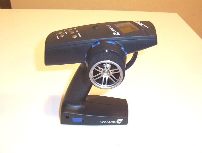
TSDNMD-AM07
Dec 28, 2006Hand Held Remote
Equipment Class
JBP - Part 15 Class B Computing Device Peripheral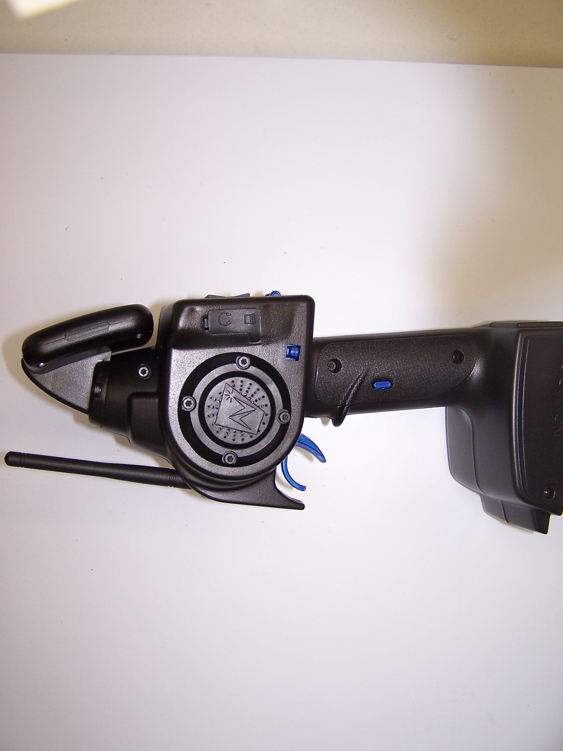
TSDNMD-AM04
Feb 01, 2006Digital R/C Controller
Equipment Class
DSS - Part 15 Spread Spectrum Transmitter
TSDNMD-AM05
Jan 24, 2006Secure Radio Module
Equipment Class
DSS - Part 15 Spread Spectrum Transmitter
TSDNMD-AM06
Jan 22, 2006Robot Control Unit
Equipment Class
DSS - Part 15 Spread Spectrum Transmitter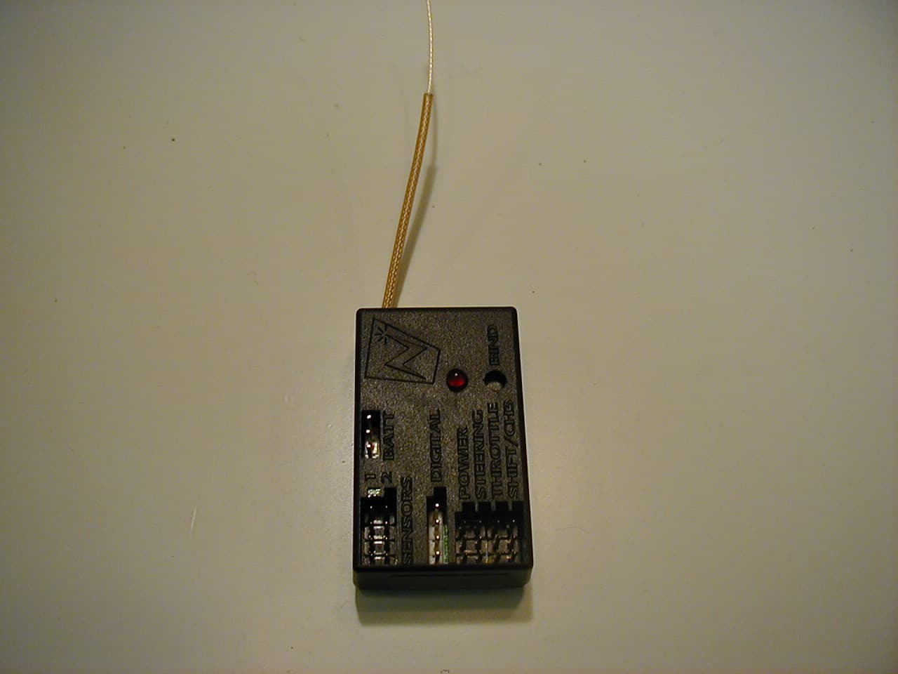
TSDNMD-AM03
Dec 01, 2005Remote Control Vehicle Transceiver Module
Equipment Class
DSS - Part 15 Spread Spectrum Transmitter