TSDNMD-AM07Hand Held Remote
Nomadio, Inc.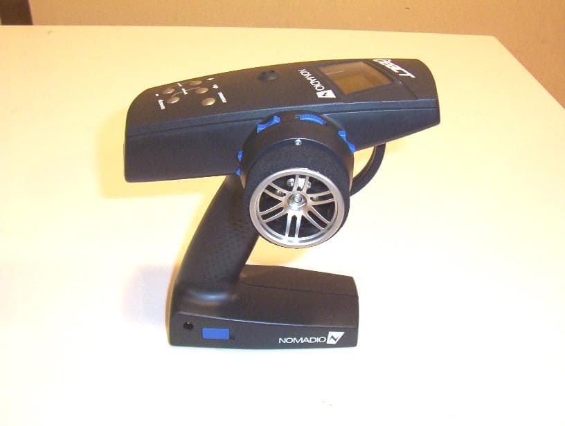
Click to zoom
Application Details
- Equipment Class
- JBP - Part 15 Class B Computing Device Peripheral
- Date of Grant
- Dec 28, 2006
- Application Purpose
- Original Equipment
- Date of Application
- Dec 23, 2006
- Equipment Note
- Hand Held Remote
- Company
- Nomadio, Inc.
- Country
- United States
Documents & Files
Document Text
Text extracted from the exhibit documents filed with the FCC. Open a document above to read the original.
Users Manual
Link to Download Desktop Software: WWW.SUPPORT.NOMADIO.NET/REACT User’s Guide Link to Download Desktop Software: WWW.SUPPORT.NOMADIO.NET/REACT Copyright 2006 Nomadio Published November, 2006 Table of Contents Getting to Know Your React.................................................................................................................7 Power Switch...............................................................................................................................7 Display Screen .............................................................................................................................7 Navigation Buttons ......................................................................................................................8 Selection Buttons .........................................................................................................................8 Trim Buttons................................................................................................................................9 Grip Buttons ................................................................................................................................9 Charging and Installing Batteries ......................................................................................................9 Installing the Batteries ......................................................................................................................9 Charging the Batteries ....................................................................................................................10 Installing the Transceiver................................................................................................................11 Mounting the Transceiver ..........................................................................................................11 Connecting the Transceiver ........................................................................................................11 Servo Connection..............................................................................................................12 FCC Compliance Reminder ..............................................................................................12 Installing the Optional Sensors............................................................................................................12 Receiver Battery Sensor .................................................................................................................12 Voltage Sensor ...............................................................................................................................12 Temperature Sensor........................................................................................................................13 Installation ......................................................................................................................................... 13 Connection .....................................................................................................................................13 Tachometer Sensor .........................................................................................................................14 Installation ..........................................................................................................................................14 2. Install the magnets ......................................................................................................................... 14 Connection .....................................................................................................................................15 Connecting the Tach Sensor ................................................................................................................15 Binding the Transceiver..................................................................................................................16 How the Binding Process Works ................................................................................................16 Binding your transceiver the first time.................................................................................................16 React Controls................................................................................................................................16 Top Menu Level ........................................................................................................................18 Steering Functions ..........................................................................................................................18 Steering Trim.............................................................................................................................18 Adjusting Steering Trim using the Function Menu .....................................................................19 Adjusting Steering Trim using the Steering Trim Buttons ..........................................................19 Steering Dual Rate .....................................................................................................................20 Adjusting Steering Dual Rate using the Function Menu .............................................................21 Adjusting Steering Dual Rate using the Trim Buttons ................................................................22 Dual Rate and End Point Adjustment .........................................................................................22 Steering Exponential ..................................................................................................................22 Adjusting Steering Exponential ......................................................................................................23 Steering Sub-Trim..............................................................................................................…
Text truncated - open the document above for the full version.
Users Manual
set up your limiting. Throttle Speed determines the percentage of full speed that is applied to the throttle movements that are above the throttle trigger setting. 100 is maximum servo movement rate. 1 is minimum rate. Default is 100 (full speed). Brake Speed determines the percentage of full speed that is applied to braking movements that are above the trigger setting. 100 is maximum servo movement rate. 1 is minimum rate. Default is 100 (full speed). Throttle Trigger sets the minimum amount of control input before the speed limiter becomes active. At 0%, limiting is always active (input is always >= 0%). At 50%, limiting is only active if the throttle is on half way or more. Brake Trigger sets the minimum amount of control input before the speed limiter becomes active. At 0%, limiting is always active (input is always >= 0%). At 50%, limiting is only active if the brake is on half way or more. Changing the Throttle Speed Use the navigation controls to change the steering servo type as follows: 1. Access the top function menu from the driving screen. 2. Navigate to the Steering (Ch1) menu. or then 3. Navigate to Throttle Speed. or Value Description Throttle Speed The amount of limiting applied to servo throttle motion once the trigger amount has been exceeded. 4. Change the values. or Brake Speed The amount of limiting applied to servo brake motion once the trigger amount has been exceeded. Throttle Trigger The percentage of full throttle range that will be limited. Brake Trigger The percentage of full braking range that will be limited. Interaction with other Settings Servo Speed is applied after Expo. The trigger levels refer to the curved input value. ABS is applied after Brake Speed, so Brake Speed can limit how quickly the brake input moves to the ABS Active region, but once there ABS pulses happen at full speed. Servo Speed is applied after AutoStart, so if the AutoStart Level is set higher than the Throttle Speed Trigger, the servo movement will be slowed. Idle Up only takes effect when the trigger is centered. Throttle Speed can slow down the return to center, and therefore slow down Idle Up activation. Once Idle Up is started, the servo will jump to the set position. Channel 3 and Channel 4 Servo Functions Each of these servos can be used as a number of auxiliary functions such as shifting or acting as a second braking or steering servo. The following illustration shows the function menu structure for Channel 3 (Shift) and Channel 4 (Power): Channels 3 / 4 Servo Trim Channel 3 and Channel 4 servo trim adjusts the resting (centered) positions of the servos. When initially setting up the vehicle, the shift servo trim setting should be set to 0. On the servo, the servo horn should be positioned as appropriate on the servo. On the driving screen, Channel 3 and Channel 4 servo trims are represented by the position of the pointers on the bottom bars. Ch3 and Ch4 Trims Changing the servo trim has the following visual effect on the driving screen bars: Servo trim is centered in range (value = 0) Servo trim is offset to high end (+ve value) Servo trim is offset to low end (-ve value) Adjusting Channel 3 / 4 Servo Trims Use the navigation controls to adjust shift servo trim as follows: 1. Access the top function menu from the driving screen. 2. Navigate to the Channel 3 or Channel 4 menu. or then 3. Navigate to Trim. or Value Description 0 Shift servo trim is centered within the servo range. -ve value (-100 Æ -1) Shift servo trim is to the LOW end. 4. Change the value. or +ve value (1 Æ 100) Shift servo trim is to the HIGH end. Trim and EPA Interaction A trim (or sub-trim) setting of 100 is equivalent to an End point setting of 50. Channel 3 / 4 Servo Dual Rate Channel 3 and Channel 4 servo dual rates adjust the range of servo movement when the grip buttons are activated. The servo dual rate value is applied to both low and high ends, and is expressed as a percentage of servo range (configured by end point adjust ments). On the driving screen, servo dual rate range is represented by the solid length of the bottom bar. The total length of the bar (solid and dotted) represents the servo range. The length of the solid bar represents the servo range as set by the dual rate value. Ch3 / Ch4 Dual Rate Ranges Changing the dual rate setting has the following visual effect on the driving screen bars: Full servo range is used. Lower dual rate value reduces servo range. Adjusting Channel 3 /4 Servo Dual Rate Use the navigation controls to adjust servo dual rate as follows: 1. Access the top function menu from the driving screen. 2. Navigate to the Channel 3 or Channel 4 menu. or then 3. Navigate to Dual Rate. or Value Description 0 Servo range is set to minimum (0%). 1-99 Servo range is set to a percentage of full range. For example, value “50” gives 50% of full servo range. 4. Change the value. or 100 Servo range is set to full (100%) Dual Rate and End Point Adjustment Full servo range is determined by the shift servo low and high end point adjustments. The dual rate value determines the relative servo range between the low and high end points. The servo will never mo ve beyo nd the set end point adjust ments, no matter what dual rate setting is applied. Low End Point The servo low end point value adjusts the shift servo’s starting position at reset. This is intended to be low gear and goes with the downshift sound event (reverse the servo if this is not the case on your model). The end point adjustments should be adjusted prior to other settings. The low end point is set independently of the high end point (which adjusts how far the servo moves to the HIGH end). On the driving screen, the low end point is represented by the length of the bar to the left of the pointer on the lower bar. The greater the left length of the bar, the greater the low end point value. The position of the pointer on the bar is affected by end point settings (low and high) and trim setting. Ch3 / Ch4 Low End Points Low en…
Text truncated - open the document above for the full version.
Block Diagram
CPU ADCs, Digital I/Os Core Logic Program Memory T im e r s A n t e n n a System Clock 12MHz U S B Voltage Regulator ButtonsSwitches Steering Pot Radio System Radio IC Power Amp Antenna Switch Radio Clock 13MHz CPU Clock 12MHz CPU Voltage Regulator To PC B a t t e r i e s Throttle Trigger DC Input Jack Vin
Cover Letter(s)
American Telecommunications Certification Body Inc. 6731 Whittier Ave, McLean, VA 22101 December 18, 2006 RE: Nomadio, Inc. FCC ID: TSDNMD-AM07 After a review of the submitted information, I have a few comments on the above referenced Application. 1) The block diagram should show the frequencies of all oscillators in the TX device (CFR 2.1033(a)(5)), unless this portion of the device is an OEM part from a different manufacturer. Please provide either the block diagram for the TX portion, or alternatively provide a parts list that shows that this part is provided by another manufacturer. Please update the list of confidential exhibits if necessary. 2) The TX appears to be a small mounted daughter board. The top and bottom of this board should be shown (likely will require to be provided from the manufacturer so the EUT isn’t damaged). Additionally a view with the shield removed is also required. 3) A users manual (per our previous discussion) does not appear to be uploaded or received via email. 4) The users label is located inside the battery compartment. The FCC has recently (past 3 months) started requiring that all devices (other than cellphones or cordless phones) must be discussed with the FCC to obtain permission for this (See info released to TCB’s below in November). Note this will take some time and the result is not always favorable. If the applicant wishes for us to pursue this, please provide information as asked below. Alternatively a new label placement and exhibit can be provided. Labeling Non-routine label proposals such as placing the label in the battery compartment must be approved on a case by case basis. For each proposal, provide justification such as limited space, how the FCC identifier or label will be viewable and how pertinent rule parts such as 2.925(d) (readily visible at the time of purchase) will be complied with. Please use the “Permit but ask” procedure and submit proposals to the KDB. Please provide photos and a grantee signed proposal. 5) This device appears to be capable of USB connection to a PC (see block diagram) and is therefore also considered a PC peripheral device (in addition to the TX requirements) and is subject to either a Certification or DoC as a PC peripheral. Therefore the application must clarify if you are asking for: a) Certification of the device as a TX, and a DoC has been performed by an appropriately accredited test lab for a PC peripheral b) Certification as a TX + PC peripheral. Note 1: The option b) would be considered as a composite application and 2 certificates (one for the TX, one for the PC peripheral portion) would be issued. Note that there are additional review costs associated with this additional certification. Note 2: To qualify to perform DoC applications, the test lab must be accredited (i.e. NVLAP or A2LA) to perform testing under the DoC procedure. z Page 2 December 19, 2006 Note 3: Note that for DoC tests, the device is configured with a minimum test configuration as specified by ANSI C63.4 which includes complete computer + 2 I/O devices attached (one may be the EUT) during this particular test. Please note that the current test photographs do not support a minimum configuration of 2 I/O Devices. Note 4: Each path (DoC or Certificaiton) has particular labeling requirements that must be followed. For DoC authorizations, the label should also include specific DoC labeling information and also the users manual should include information regarding Part 2.1077. If the device is Certified, the FCC ID and current labeling requirements for the TX will cover the labeling requirements. However, additional grants are generated and review costs are higher. Please note that currently labeling and users manual do not support a DoC. Note 5: The manufacturer does have a choice of DoC or Certification, however the device labeling and manual information must match the appropriate methods used. 6) This device shall use a pseudorandomly ordered list of hopping frequencies. Please provide a sample hopping table. 7) Please provide information showing compliance with 15.247(g)/(h). 8) Please provide an appropriate RF exposure exhibit as a separate exhibit. 9) It appears that average data may have been measured. This is allowed if the carrier is non- pulsing. If the carrier was pulsing, then average measurements are actually obtained correcting the peak by the appropriate worse case duty factor in any 100 msec of time. Please review. 10) FYI....Although the labeling provided is acceptable to the FCC, please inform the applicant the preferred format is “FCC ID:”. They should consider use of this in the future. Timothy R. Johnson Examining Engineer mailto: [email protected] The items indicated above must be submitted before processing can continue on the above referenced application. Failure to provide the requested information may result in application termination. Correspondence should be considered part of the permanent submission and may be viewed from the Internet after a Grant of Equipment Authorization is issued. Please do not respond to this correspondence using the email reply button. In order for your response to be processed expeditiously, you must submit your documents through the AmericanTCB.com website. Also, please note that partial responses increase processing time and should not be submitted. Any questions about the content of this correspondence should be directed to the sender.
Cover Letter(s)
Dear Tim, Please find attached are the requested information with some explanation as below: 1. Submitted a revised Block diagram with frequencies. 2. Submitted a TX Top and Bottom pix/drawing Images. Please note that we could take picture with shield on it (Top view of the board - top left side pix). Others are drawing images. The bottom of the TX board does not have any components. 3. Submitted a revised manual with lesser file size (less then 4 MB). 4. Submitted a new FCC label drawings and Pix for FCC label location. Please note that the Nomadio would place both the labels, that having same FCC ID number, at the outside of bottom cover. 5. Nomadio would like to go for Certification with understanding that repeat of testing will not be required. Please provide additional cost estimate. 6. Please see attached document: Section 15.247(g/h) Declarations REACT FHSS. 7. Information has been included in Section 15.247(g/h) Declarations REACT FHSS 8. A separate exhibit for RF exposure evaluation is attached. 9. Radiated emissions test data has been reviewed, no further action determined. 10. Noted for future submission. Thank you very much. Dipak >From: Timothy R. Johnson [mailto:[email protected] ] >Sent: Tuesday, December 19, 2006 2:25 AM >To: Patel, Dipak J ...snip... >NARTE Certified EMC Engineer >No. EMC-002205-NE > >email: [email protected] >alternate email: [email protected] Block Diagram with Frequencies.pdf TX (N -Link) Top and Bottom Images.pdf Users Manual2.pdf Label Drawing and Location2.pdf Subject: Additional Information, FCC ID: TSDNMD-AM07 From: "Patel, Dipak J" <[email protected]> To: Timothy R. Johnson <[email protected]> Section 15.247_gh_ Declarations REACT FHSS.pdf RF Exposure Evaluation2.pdf
Cover Letter(s)
American Telecommunications Certification Body Inc. 6731 Whittier Ave, McLean, VA 22101 December 22, 2006 RE: Nomadio, Inc. FCC ID: TSDNMD-AM07 After a review of the submitted information, I have a few comments on the above referenced Application. 1) Please confirm the explanation of the placement of the label. The sample label appears to place the label on the outside of the bottom of the chassis. The response appears to state the cover. Please note that labels are not acceptable to place on battery covers. Please review/explain. 2) Per our discussion of 12/21/06, please note that a PC peripheral device requires a minimum configuration as specified by section 11.2 of ANSI C63.4. Please correct. 3) If adding a PC Peripheral Certification, please update the 731 page to add JBP as well. 4) Regarding average data, please explain. When a device has pulsed emissions, the FCC has required duty factor calculations and has not accepted average measurements. More explanation is necessary. Please explain. Timothy R. Johnson Examining Engineer mailto: [email protected] The items indicated above must be submitted before processing can continue on the above referenced application. Failure to provide the requested information may result in application termination. Correspondence should be considered part of the permanent submission and may be viewed from the Internet after a Grant of Equipment Authorization is issued. Please do not respond to this correspondence using the email reply button. In order for your response to be processed expeditiously, you must submit your documents through the AmericanTCB.com website. Also, please note that partial responses increase processing time and should not be submitted. Any questions about the content of this correspondence should be directed to the sender.
Cover Letter(s)
Dear Tim, Please find attached are the requested information with some explanation as below: 1. The FCC label will be placed on the bottom surface of the React, next to the battery door (cover). The FCC label will not be placed on the battery cover but it would be next to the battery cover. The picture showing the FCC label and its location with text information is submitted with this email. 2. For the reevaluation of React USB operation per ANSI requirements, a second I/O (Ethernet) was added to the Laptop PC. Other end of the Ethernet cable was connected to the Netgear model GS516T Ethernet Hub, placed below the ground plane. Radiated emissions and conducted emission scans for the USB operation with having second I/O (Ethernet) connected to the laptop PC were performed. With respect to the FCC Class B emission limits, no significant difference between the emission characteristics obtained with only the USB interface connection to the Laptop PC and that of with having added Ethernet I/O connection to the Laptop PC. Therefore the original data submitted for the USB operation without second I/O to the Laptop PC remains still valid where it shows compliant with the FCC Class B limit requirements. Test setup photos and test setup block diagram are attached. 3. We would like to request for adding PC Peripheral Certification. I have revised React ATCB - Form 731, accordingly and attached with this email. 4. For the average data, the worse case duty cycle correction factor in any 100 msec time has been determined as below: Duty Cycle Correction Factor: = 20 Log (Dwell time in ms /100 ms) dB = 20 log (9.338 ms /100 ms) db = - 20.6 db Thus, the amplitudes of average measurements data obtained from correcting the peak data, by worse case duty cycle factor, would be 20.6 dB lower then the peak data. Since the difference between the applicable FCC Peak emission limit and average emission limit is 20 db and all the recorded peak data were found below the applicable FCC Peak emission limit, therefore it can be concluded that the average data also meet the applicable FCC average emission limit. I believe this concludes my actions. I would like to wish you a great enjoyable time with your family in these holidays. Thank you very much Dipak Patel Unisys Corporation
Cover Letter(s)
Attn:Reviewing Engineer Federal Communications Commission 7435 Oakland Mills Road Columbia, MD 21046 8 November 2006 RE: CONFIDENTIALITY REQUEST FOR NOMADIO REACT TSDNMD-AM07 To Whom It May Concern: This letter serves as an official request for confidentiality under FCC Rule Section 0.459. We have requested that the schematic diagrams required to be submitted with this application be withheld from public review. The documents are company proprietary information that should never be in the possession of our competition. Please contact me if there is any information you may need. Sincerely, Alex Gizis, CEO 2400 Chestnut St. Philadelphia PA 19103 www.nomadio.net
External Photos
VOJTZT! ! PCTC Product Compliance Test Center 2476 Swedesford Road, Malvern, PA 19355 EXTERNAL PHOTOS React FCC ID: TSDNMD-AM07 NOMADIO, INC. PHILADELPHIA, PA ! VOJTZT! PCTC Page 2 of 7 Product Compliance Test Center FCC ID: TSDNMD-AM07 External Photos Photo 1: React Side View 1 VOJTZT! PCTC Page 3 of 7 Product Compliance Test Center FCC ID: TSDNMD-AM07 Photo 2: React Side View 2 VOJTZT! PCTC Page 4 of 7 Product Compliance Test Center FCC ID: TSDNMD-AM07 Photo 3: React Top Panel View VOJTZT! PCTC Page 5 of 7 Product Compliance Test Center FCC ID: TSDNMD-AM07 Photo 4: React View 1 VOJTZT! PCTC Page 6 of 7 Product Compliance Test Center FCC ID: TSDNMD-AM07 Photo 5: React View 2 VOJTZT! PCTC Page 7 of 7 Product Compliance Test Center FCC ID: TSDNMD-AM07 Photo 6: React Bottom View
ID Label/Location Info
React FCC ID: TSDNMD-AM07 FCC Label Picture Notes: (1) The size of the FCC label is approximately: 1” x 1.125” (2) The FCC label will be placed inside the battery compartment, as shown on the FCC label location Photos.
ID Label/Location Info
Nomadio React TSDNMD-AM07 FCC Labeling Diagram This label placed on the bottom surface of the unit, next to the battery door (not on the battery door).
Internal Photos
VOJTZT! ! PCTC Product Compliance Test Center 2476 Swedesford Road, Malvern, PA 19355 INTERNAL PHOTOS React FCC ID: TSDNMD-AM07 NOMADIO, INC. PHILADELPHIA, PA ! VOJTZT! PCTC Page 2 of 7 Product Compliance Test Center FCC ID: TSDNMD-AM07 Internal Photos Photo 1: Internal View with Open Covers VOJTZT! PCTC Page 3 of 7 Product Compliance Test Center FCC ID: TSDNMD-AM07 Photo 2: Close-up Front Side View VOJTZT! PCTC Page 4 of 7 Product Compliance Test Center FCC ID: TSDNMD-AM07 Photo 3: View from Bottom VOJTZT! PCTC Page 5 of 7 Product Compliance Test Center FCC ID: TSDNMD-AM07 Photo 4: View of Battery Compartment VOJTZT! PCTC Page 6 of 7 Product Compliance Test Center FCC ID: TSDNMD-AM07 Photo 5: Internal View of Top Cover VOJTZT! PCTC Page 7 of 7 Product Compliance Test Center FCC ID: TSDNMD-AM07 Photo 6: Internal View with Top Cover Removed
Internal Photos
VOJTZT! ! PCTC Product Compliance Test Center 2476 Swedesford Road, Malvern, PA 19355 PC BOARD PHOTOS React FCC ID: TSDNMD-AM07 NOMADIO, INC. PHILADELPHIA, PA ! VOJTZT! PCTC Page 2 of 3 Product Compliance Test Center FCC ID: TSDNMD-AM07 PC Board Photos Photo 1: Top View VOJTZT! PCTC Page 3 of 3 Product Compliance Test Center FCC ID: TSDNMD-AM07 Photo 2: Bottom View
Internal Photos
N-Link module, top side, with shield N-Link module, top side, without shield N-Link module, bottom side (no components this side)
Operational Description
React (FCC ID: TSDNMD-AM07) Theory of Operation Page 1 of 1 Radio System The radio transceiver is a 2.4-GHz Direct Sequence Spread Spectrum (DSSS) Gaussian Frequency Shift Keying (GFSK) baseband modem radio that connects to the central processor unit (CPU) via a serial peripheral interface (SPI). A power amplifier increases the power of the output radio signal in order to increase its effective range. The radio operates in the worldwide 2.4-GHz Industrial, Scientific, and Medical (ISM) frequency band (2.400 GHz–2.4835 GHz). It divides the ISM band into 78 channels, each of which are 1 MHz wide. DSSS generates a redundant bit pattern, known as a Pseudo Noise (PN) code for each bit to be transmitted. The receiver utilizes a copy of the same PN code as the transmitter (the system for synchronizing PN codes at connection time is described below in the Rendezvous Hopping section) and a matched filter to find signals on the same frequency which are transmitted using the same PN code. The filter will not respond to either random noise (except in very unlikely events) or signals transmitted using other PN codes. Using the DSSS radio transceiver as a base band radio, the radio system implements a frequency hopping spread spectrum (FHSS) system in software by shifting frequencies between every transmitted DSSS packet according to an agree upon pseudo-random pattern. All Nomadio's equipment operates at a data rate of 31.25kbps. Theory of Operation The React transmitter is the link master. The vehicle transceiver (separate certification) is the link slave. At startup, the slave advertises its availability by transmitting a Service message. If the slave is bound to a master, the master’s Global Unique Identifier (GUID) is included in the Service message. During this time the master and slave are unsynchronized. Each device hops through the rendezvous channel set at its own rate and offset. When the desired master (or any unbound master if the slave is unbound) detects the Service message, it replies with a Connect message containing various link parameters, including the master’s clock. The slave synchronizes its clock value to the master’s and synchronizes the start of its clock periods to the timing carried in the Connect message. From this point forward the devices hop on a synchronized basis 100 times per second. All data transmission is initiated by the master. During most timeslots, the master sends a packet of command data to the slave, and the slave responds with an Ack message on the same channel. If the master is ready for new telemetry information it sends a request as part of its command packet. The slave then sends a data packet on the following timeslot, using the channel the request was received on.
Operational Description
TSDNMD-AM04 REACT FHSS Section 15.247(a): Describe how the EUT meets the definition of a frequency hopping spread spectrum system, found in Section 2.1, based on the technical description. The REACT is designed with a commercially available frequency-agile digitally modulated radio ASIC. This ASIC is designed to be capable of changing frequencies between packets. The device’s firmware takes advantage of this capability by selecting a new operating frequen…
Text truncated - open the document above for the full version.
Contact Information
Applicant
Alexander Gizis(CEO)
Technical Contact
Nomadio, Inc.Alex Gizis
[email protected]215 854 8432
2400 Market St Ste 13 · Philadelphia, Pennsylvania · United States
Test Firm
UNISYS CorporationJohn Baumeister
Technical Specifications
| # | Rule Parts | Frequency Range | Power Output |
|---|---|---|---|
| 1 | 15B | - | - |
Other Applications from Nomadio, Inc.
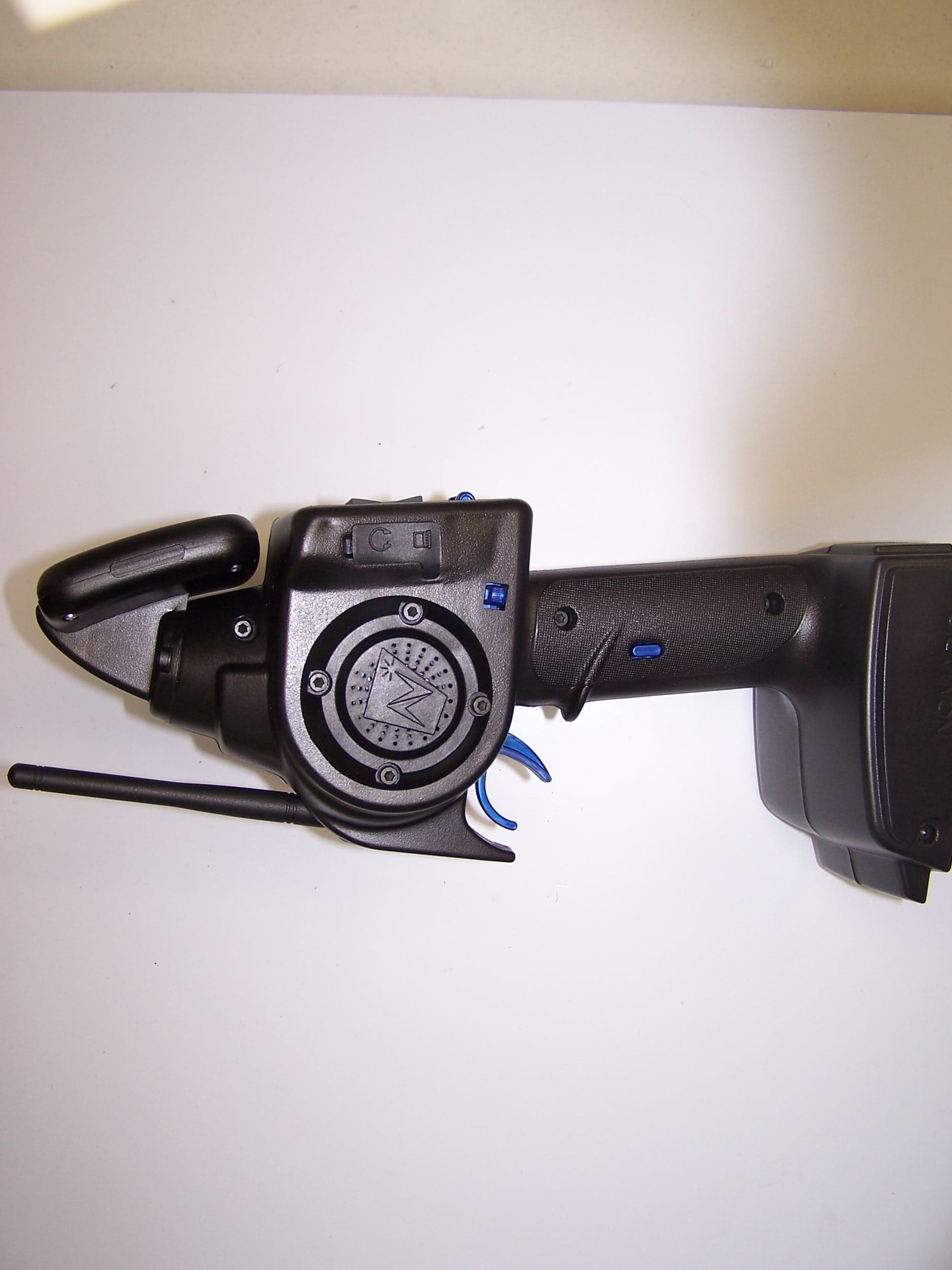
TSDNMD-AM04
Feb 01, 2006Digital R/C Controller
Equipment Class
DSS - Part 15 Spread Spectrum Transmitter
TSDNMD-AM05
Jan 24, 2006Secure Radio Module
Equipment Class
DSS - Part 15 Spread Spectrum Transmitter
TSDNMD-AM06
Jan 22, 2006Robot Control Unit
Equipment Class
DSS - Part 15 Spread Spectrum Transmitter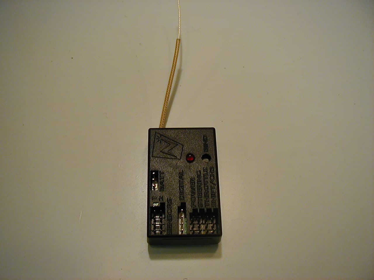
TSDNMD-AM03
Dec 01, 2005Remote Control Vehicle Transceiver Module
Equipment Class
DSS - Part 15 Spread Spectrum Transmitter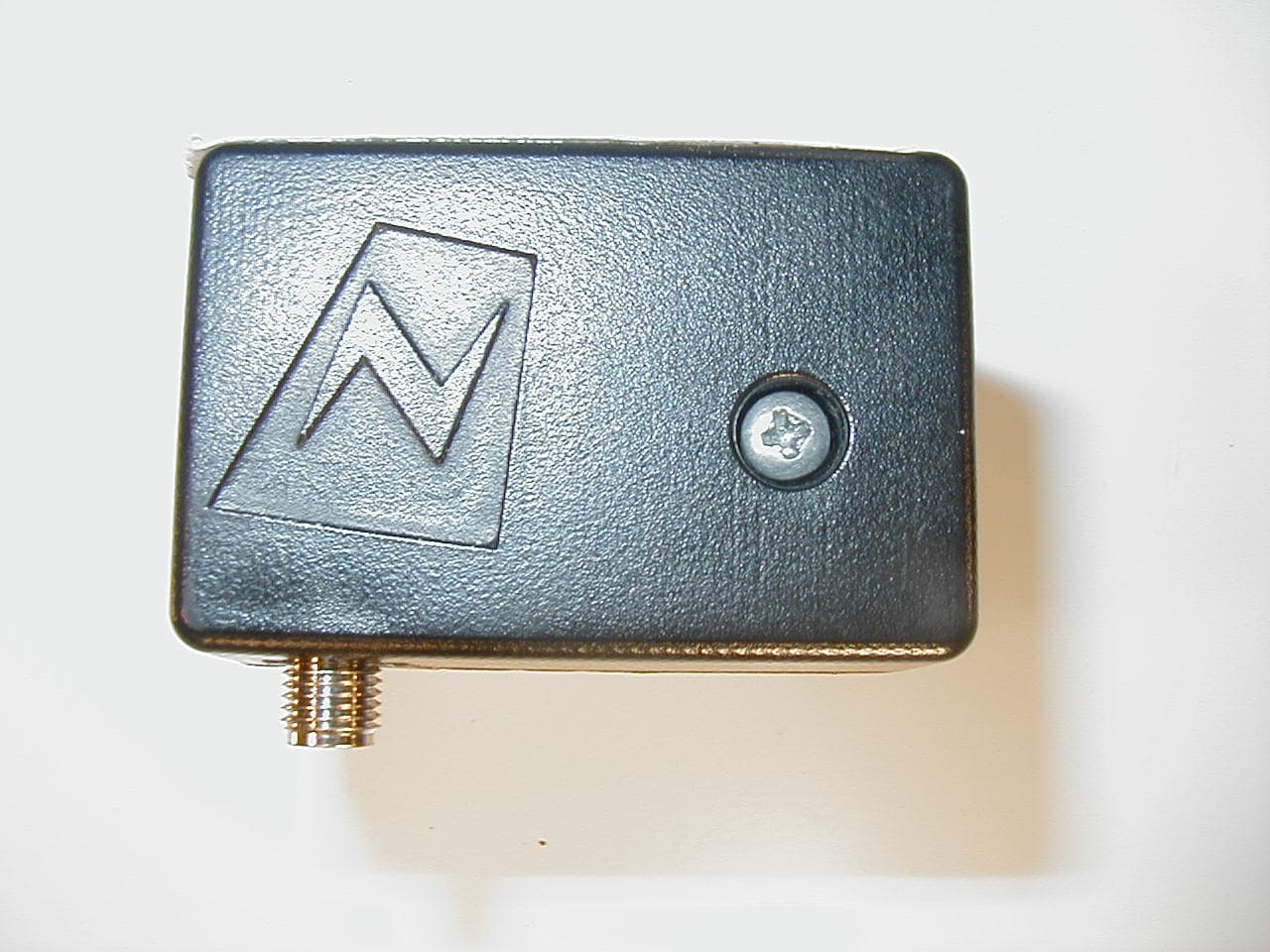
TSDNMD-AM02
Nov 15, 2005Digital R/C control system
Equipment Class
DTS - Digital Transmission System