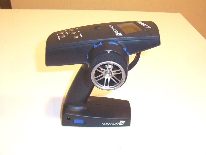
TSDNMD-AM04Digital R/C Controller
Nomadio, Inc.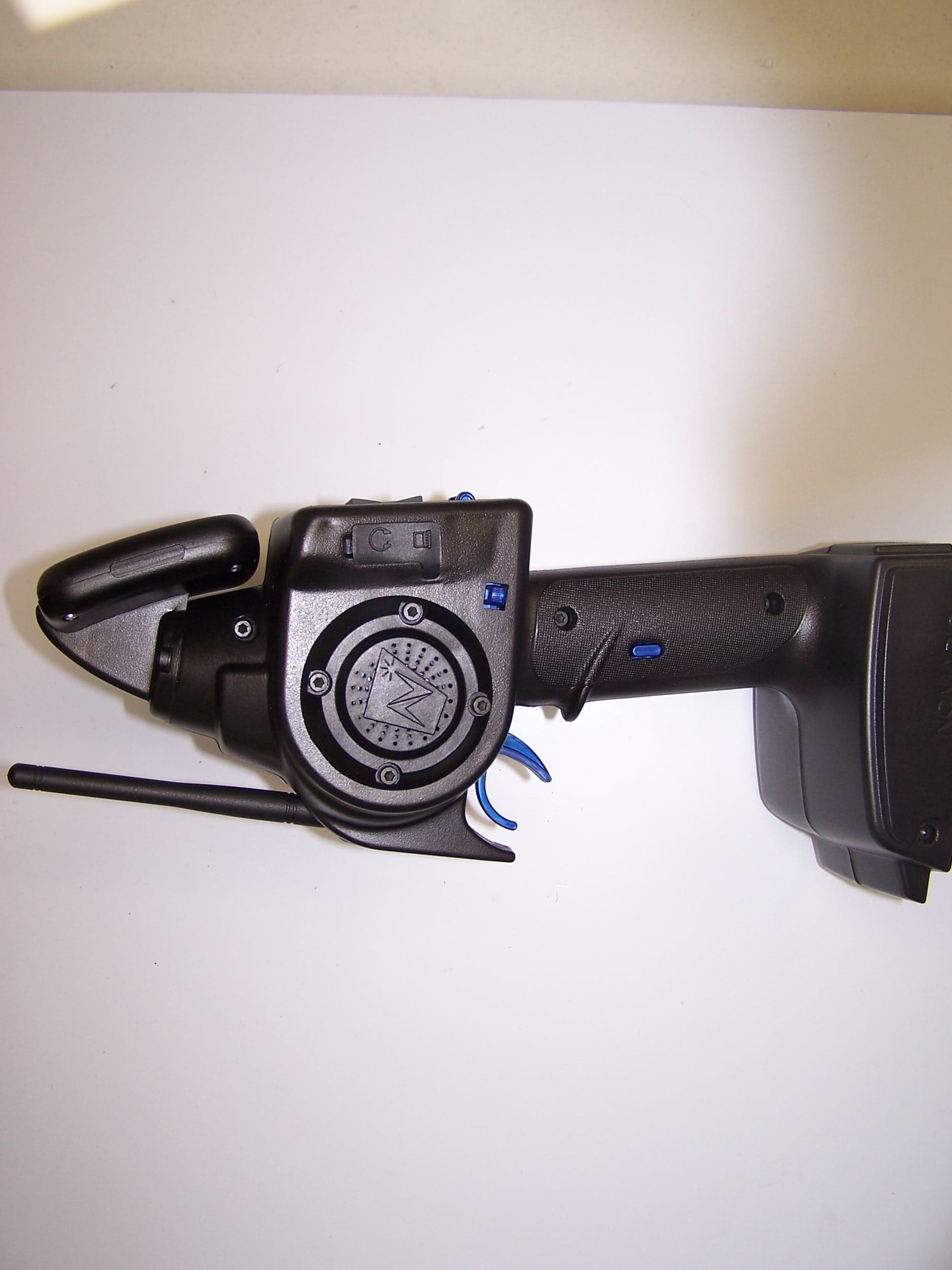
Click to zoom
Application Details
- Equipment Class
- DSS - Part 15 Spread Spectrum Transmitter
- Date of Grant
- Feb 01, 2006
- Application Purpose
- Original Equipment
- Date of Application
- Feb 01, 2006
- Equipment Note
- Digital R/C Controller
- Frequency Range
- 2402.00000000 - 2479.00000000
- Company
- Nomadio, Inc.
- Country
- United States
Documents & Files
Document Text
Text extracted from the exhibit documents filed with the FCC. Open a document above to read the original.
Users Manual
USERS GUIDE Version 2.1 Published December 2005 Sensor Quick Reference Display Screen Antenna Speaker Throttle Trigger Headphone & PC Connections Steering Trim Shift Buttons Battery Compartment / Receiver Programming Cable Steering Wheel Graphic Display Screen Navigation Controls (T1) Throttle Dual Rate Trim (T2) Steering Dual Rate Trim (T3) Throttle Trim (TR) Steering Trim (TL) Steering Trim Menu Button On/Off Switch Selection Buttons Transceiver Quick Reference Receptacle for: Car Battery Sensor Receptacles for: RX Battery (power) Steering (Ch1) Throttle (Ch2) Shift Servo (Ch3) Receptacle for: Digital Sensor (e.g., RPM/Speed ) /Receiver Programming Cable BIND button (recessed) Indicator LED Receptacles for: Analog Sensors (e.g., Temp) Driving Screen Quick Reference Graph of Servo Positions Signal Strength Current Stat Value Current Model Number Currently Displayed Stat Current Stat Bar Graph Vehicle Battery Indicator (Blinks when low) Transmitter Battery Indicator (Blinks when low) Statistics: Highest value seen of current stat. Statistics: Lowest value seen of current stat. Key Drive Screen Controls Pressing this button toggles Sensor between the driving screen and the top level function menu, or returns to the previous level from a sub-menu. Displays the previous statistic. Displays the next statistic. Contents ContentsContents Contents Sensor Quick Reference .................................II Transceiver Quick Reference ....................... III Driving Screen Quick Reference ................... IV Statement of Compliance................................1 Getting to know your Sensor ..........................3 Power Switch .......................................................... 3 Display Screen......................................................... 3 Menu Button ........................................................... 3 Navigation Buttons .................................................. 3 Selection Buttons..................................................... 4 Trim Buttons ........................................................... 4 Grip Buttons............................................................ 5 Connection Ports ..................................................... 5 Charging and Installing Batteries...................6 Charging the Supplied NiMH Batteries........................ 6 Installing the Batteries ............................................. 6 Adjusting the Screen.......................................7 Converting for Left Handed Use......................8 Installing the Transceiver .............................10 Mounting the Transceiver ....................................... 10 Connecting the Transceiver .................................... 10 Installing the Sensors ...................................11 Receiver Battery Sensor ......................................... 11 Voltage Sensor ...................................................... 11 Temperature Sensor .............................................. 11 Tachometer Sensor................................................ 13 Binding the Transceiver ................................15 How the Binding Process Works .............................. 15 Sensor Controls ............................................ 18 Top Menu Level ..................................................... 19 Steering Functions ................................................. 19 Throttle Functions.................................................. 33 Channel 3 and Channel 4 Servo Functions................ 49 Advanced Features ................................................ 59 Model Management................................................ 69 Controller Setup..................................................... 74 Sensor Digital RC Desktop............................ 79 Minimum System Requirements .............................. 79 Installing the RC Desktop ....................................... 79 Connecting the Sensor to your Computer ................. 85 Using the Sensor Digital RC Desktop........................ 86 Registration........................................................... 86 Receiving Settings From the Sensor......................... 88 Editing Settings ..................................................... 89 Saving Settings...................................................... 89 Sending Settings to the Sensor ............................... 90 Installing Sensor Firmware ..................................... 90 Specifications ............................................... 91 Sensor Controller ................................................... 91 Transceiver ........................................................... 91 Support ......................................................... 92 Nomadio 3 Year Limited Warranty ............... 93 Warranty Coverage ................................................ 93 Exclusions and Limitations ...................................... 93 1 Statement of Compliance FCC Compliance Statement This equipment has been tested and found to comply with the limits for a Class B digital device, pursuant to Part 15 of the FCC Rules. These limits are designed to provide reasonable protection against harmful interference in a residential installation. This equipment generates, uses and can radiate radio frequency energy and, if not installed and used in accordance with the instructions, may cause harmful interference to radio communications. However, there is no guarantee that interference will not occur in a particular installation. If this equipment does cause harmful interference to radio or television reception, which can be determined by turning the equipment off and on, the user is encouraged to try to correct the interference by one or more of the following measures: – Reorient or relocate the receiving antenna. – Increase the separation between the equipment and receiver. – Connect the equipment into an outlet on a circuit different from that to which the receiver is connec…
Text truncated - open the document above for the full version.
Attestation Statements
TSDNMD-AM04 Sensor FHSS Section 15.247(a): Describe how the EUT meets the definition of a frequency hopping spread spectrum system, found in Section 2.1, based on the technical description. The Sensor is designed with a commercially available frequency-agile digitally modulated radio ASIC. This ASIC is designed to be capable of changing frequencies between packets. The device’s firmware takes advantage of this capability by selecting a new operating frequency 100 times per second. The ASIC uses GFSK modulation and is operated with carrier frequencies on 1 MHz steps from 2402 MHz to 2479 MHz, for a total of 78 channels. Output power is below 125 mW, so the maximum permissible 20 dB bandwidth by Section 15.247(a)(1) is 1.5 MHz. The system hopping rate is 100 Hz. Link initialization uses a reduced hop set of 15 frequencies. This reduces the time spent in an unsynchronized state, while complying with the requirements of Section 15.247(a)(1)(iii). The ASIC’s digital modulation capabilities are used to provide enhanced robustness through interference detection due to redundant data transmission. The radio is never operated on a static carrier frequency, so the hybrid rules of Section 15.247(f) do not apply. Pseudorandom Frequency Hopping Sequence Describe how the hopping sequence is generated. Provide an example of the hopping sequence channels, in order to demonstrate that the sequence meets the requirement specified in the definition of a frequency hopping spread spectrum system, found in Section 2.1. The hopping sequence is generated in a manner compatible with other Nomadio devices. Some remote devices, such as the GC-205 RCU, use a reduced frequency set. The Sensor adapts its hop sequence to match the capabilities of the linked device. This is accomplished by adapting the basic Nomadio hop sequence to use only those frequencies available on the linked device. The basic hop set includes 79 channels from 2402 MHz to 2480 MHz. If the generated channel is enabled that channel is used for the current slot. If the channel is not enabled a replacement is selected from the list of enabled channels. Basic Hop Sequence The basic hop sequence selects frequencies from a 79-entry list. The list is ordered so that any 32-channel span in the list covers at least 64 MHz of spectrum. This is accomplished by listing all even channels (2402 MHz to 2480 MHz) followed by all odd channels (2403 MHz to 2479 MHz). TSDNMD-AM04 Sensor FHSS A 32-channel wide window is initialized to point into the list. The 32-selected channels are shuffled for the next 32 hops, so that each channel is used exactly once. When all 32 entries from the current window have been used once, the window is advanced 16 entries in the table, in a circular fashion (the first table entry, 2402 MHz, is considered to immediately follow the last entry, 2479 MHz) and the control inputs to the shuffle stage are changed. After the window has been advanced 79 times it returns to the starting position. This occurs after 79 × 32 = 2528 hops. There are 2 14 possible shuffle patterns, used over the course of 2 19 hops. When all patterns have been used, the phase of the 5-bit shuffle data input is changed. This increases the period of the shuffle output to 2 24 hops. When this period expires, however, the sliding window will not be in the starting position. The two periods will not align until 79 × 2 24 hops, at which point the pattern repeats. At 100 frames per second this is approximately 151 days of continuous operation, well in excess of the normal operational period of the system. Because the base operation is a 32-channel shuffle, it is impossible for any single channel to be used on more than two consecutive slots, which only occurs if the channel is last in one shuffle and first in the next shuffle. Every channel is used 32 times in a 2528 hop cycle. Each stage of calculation includes an exclusive-or with a portion of the link GUID. This ensures that two linked pairs will follow different hopping sequences, even if their positions in the hop sequence happen to be closely synchronized. Limiting Channel Use After a channel is generated by the basic sequence it is checked against the list of usable channels. If the channel is not usable a replacement is selected. The replacement is chosen using the shuffle output index (0-31) along with a sliding window into the list of used channels. The window is moved each time the base sequence window is moved. The used channel list is equivalent to the base channel list with unused channels removed. That is, all even used channels are listed followed by all used odd channels. When the used channel set contains 32 or more channels, a given replacement channel can be used at most once for a given 32-channel shuffle. If fewer than 32 channels are in use (such as during rendezvous) a channel may be used as a substitute more than once in a 32-channel shuffle. Over time, as the selection window is moved through the hop set, each channel will be used the same number of times as any other. Channel Set Selection The Sensor can use four different hop sets, depending on device configuration and the nature of the linked device. These hop sets include a full-band 78 channel hop set, a full- band 15-channel hop set for rendezvous, a 32-channel hop limited to the upper portion of the band, and a 15-channel rendezvous hop set limited to the upper portion of the band. TSDNMD-AM04 Sensor FHSS The rendezvous hop set is set at system configuration time, depending on the nature of the intended remote device. Six channels are shared between the two rendezvous sets, allowing connections between GC-series devices and Sensor devices. When a connection is established, the remote device selects the hop set used for the connection. Channel Sets Rendezvous 3, 8, 13, 18, 23, 28, 33, 38, 43, 48, 53, 58, 63, 68, 73 Full Band Connected 0, 1, 2, ... 75, 76, 77 Rendezvous 48, 53, 58, 63, 68, 73, 50, 54, 57, 61, 64, 67, 71, 74, 77Reduced Band Conn…
Text truncated - open the document above for the full version.
Block Diagram
LCD Interface USB Interface Speaker Driver CPU ADC Inputs Digital I/O Core Logic Program Memory T i m e r s A n t e n n a System Clock B a t t e r i e s Voltage Regulator Throttle Pot Interface Buttons Toggle Switches Steering Pot Radio System Radio IC Power Amp Antenna Switch Radio Clock Nomadio Sensor TSDNMD-AM04 Block Diagram Copyright © 2005, 2006 / Company Confidential
Cover Letter(s)
Attn:Reviewing Engineer Federal Communications Commission 7435 Oakland Mills Road Columbia, MD 21046 19 January 2006 RE: CONFIDENTIALITY REQUEST FOR NOMADIO SENSOR TSDNMD-AM04 To Whom It May Concern: This letter serves as an official request for confidentiality under FCC Rule Section 0.459. We have requested that the schematic diagrams required to be submitted with this application be withheld from public review. The documents are company proprietary information that should never be in the possession of our competition. Please contact me if there is any information you may need. Sincerely, Alex Gizis, CEO 2400 Chestnut St. Philadelphia PA 19103 www.nomadio.net
ID Label/Location Info
Nomadio Sensor TSDNMD-AM04 FCC Labeling Diagram This device complies with part 15 of the FCC Rules. Operation is subject to the following two conditions: (1) This device may not cause harmful interference, and (2) this device must accept any interference received, including interference that may cause undesired operation.
RF Exposure Info
Electromagnetic Compatibility Nomadio Digital Telemetry Emission Criteria Sensor FHSS, Model AM04 CFR Title 47, Part 15, Subpart B and Subpart C MET Report: EMC18442-FCC247 © 2006, MET Laboratories, Inc. Page 35 of 67 DOC-EMC702 2/26/2004 3.7 RF Exposure RF Exposure Requirements - §15.247(i): Systems operating under the provisions of this section shall be operated in a manner that ensures that the public is not exposed to radio frequency energy levels in excess of the Commission’s guidelines. RF Radiation Exposure Limits: §1.1310: As specified in this section, the Maximum Permissible Exposure (MPE) Limit shall be used to evaluate the environmental impact of human exposure to radiofrequency (RF) radiation as specified in Sec. 1.1307 (b), except in the case of portable devices which shall be evaluated according to the provisions of Sec. 2.1903 of this chapter. Frequency Range (MHz) Electric Field Strength (V/m) Magnetic Field Strength (A/m) Power Density (mW/cm²) Average Time (minutes) (A) Limits for Occupational / Control Exposures 30 - 300 61.4 0.163 1.0 6 300 – 1500 -- -- F/300 6 1500 – 100,000 -- -- 5 6 (B) Limits for General Population / Uncontrolled Exposure 30 - 300 27.5 0.073 0.2 30 300 – 1500 -- -- F/1500 30 1500 – 100,000 -- -- 1.0 30 Table 9. Limits for Maximum Permissible Exposure (MPE) Note: F = Frequency in MHz Test Results: MPE Limit Calculation: the EUT’s operating frequencies @ 2402 – 2479 MHz; conducted power = 11.60 dBm (peak) with maximum antenna gain of 2 dBi. Therefore, Limit for Uncontrolled exposure: 1 mW/ cm ² or 10 W/m ² Equation from page 18 of OET 65, Edition 97-01 S = PG / 4πR² or R = √PG / 4πS Where, S = Power Density (10 W/m²) P = Power Input to antenna (0.0145 Watts) G = Antenna Gain (1.6 numeric) R = distance to the center of radiation of antenna (in meter) R = √( (0.0145 x 1.6) / 4 π 10) = 0.0136 m The distance between the human and the RF antenna should not be less than 0.0136 m. Test Engineer: Dusmantha Tennakoon, Test Date: December 21, 2005
Test Report
MET Laboratories, Inc. Safety Certification - EMI - Telecom Environmental Simulation 914 WEST PATAPSCO AVENUE ! BALTIMORE, MARYLAND 21230-3432 ! PHONE (410) 354-3300 ! FAX (410) 354-3313 The Nation’s First Licensed Nationally Recognized Testing Laboratory Nomadio Digital Telemetry January 18, 2006 2400 Chestnut Street Philadelphia, PA 19103 Dear Alex Gizis, Enclosed is the EMC test report for compliance testing of the Nomadio Digital Telemetry, Sensor, Model AM04, as tested to the requirements of Title 47 of the CFR, Ch. 1 (10-1-03 ed.), Part 15 Subpart C, §15.247 for Intentional Radiators and FCC Declaration of Conformity under CFR, Part 15, Subpart B For a Class B Unintentional Radiator. Thank you for using the services of MET Laboratories, Inc. If you have any questions regarding these results or if MET can be of further service to you, please feel free to contact me. Sincerely yours, MET LABORATORIES, INC. Nicole E. Hellen Documentation Department Reference: (\Nomadio Digital Telemetry\ Sensor, Model AM04\ EMC18442-FCC247) Certificates and reports shall not be reproduced except in full, without the written permission of MET Laboratories, Inc. While use of the National Voluntary Laboratory Accreditation Program (NVLAP) letters or the NVLAP Logo, the Standards Council of Canada Logo, A2LA, or the Nationally Recognized Testing Laboratory (NRTL) Letters in this report reflects MET Accreditation under these programs, these letters, logo, or statements do not claim product endorsement by these organizations or any Agency of the U.S. Government. This letter of transmittal is not a part of the attached report. DOC-EMC702 2/26/2004 MET Laboratories, Inc. Safety Certification - EMI - Telecom Environmental Simulation 914 WEST PATAPSCO AVENUE ! BALTIMORE, MARYLAND 21230-3432 ! PHONE (410) 354-3300 ! FAX (410) 354-3313 DOC-EMC702 2/26/2004 Certificates and reports shall not be reproduced except in full, without the written permission of MET Laboratories, Inc. Electromagnetic Compatibility Test Report For the Nomadio Digital Telemetry Sensor, Model AM04 Tested in Accordance with Title 47 of the CFR FCC Part 15, Subpart B and Subpart C MET Report: 18442-FCC247 January 18, 2006 Prepared For: Nomadio Digital Telemetry 2400 Chestnut Street Philadelphia, PA 19103 Prepared By: MET Laboratories, Inc. 914 West Patapsco Avenue Baltimore, MD 21230 Nomadio Digital Telemetry Sensor, Model AM04 CFR Title 47, Part 15, Subpart B and Subpart C MET Report: EMC18442-FCC247 © 2006, MET Laboratories, Inc. Page i of iv DOC-EMC702 2/26/2004 Electromagnetic Compatibility Test Report For the Nomadio Digital Telemetry Sensor, Model AM04 Tested in Accordance with Title 47 of the CFR FCC Part 15, Subpart B and Subpart C Dusmantha Tennakoon Nicole E. Hellen Electromagnetic Compatibility Lab Documentation Department Engineering Statement: The measurements shown in this report were made in accordance with the procedures indicated, and the emissions from this equipment were found to be within the limits applicable. I assume full responsibility for the accuracy and completeness of these measurements, and for the qualifications of all persons taking them. It is further stated that upon the basis of the measurements made, the equipment tested is capable of operation in accordance with the requirements of Part 15, §15.247 of the FCC Rules under normal use and maintenance. Kevin Mehaffey Manager, Electromagnetic Compatibility Lab Nomadio Digital Telemetry Sensor, Model AM04 CFR Title 47, Part 15, Subpart B and Subpart C MET Report: EMC18442-FCC247 © 2006, MET Laboratories, Inc. Page ii of iv DOC-EMC702 2/26/2004 Report Status Sheet Revision Report Date Reason for Revision Ø January 18, 2006 Initial Issue. Nomadio Digital Telemetry Sensor, Model AM04 CFR Title 47, Part 15, Subpart B and Subpart C MET Report: EMC18442-FCC247 © 2006, MET Laboratories, Inc. Page iii of iv DOC-EMC702 2/26/2004 List of Terms and Abbreviations AC Alternating Current ACF Antenna Correction Factor Cal Calibration d Measurement Distance dB Deci Bels dBFV Deci-Bels above one micro Volt dBFV/m Deci-Bels above one micro Volt per meter DC Direct Current DCF Distance Correction Factor E Electric Field EUT Equipment Under Test f Frequency FCC Federal Communications Commission H Magnetic Field GHz Giga Hertz Hz Hertz ICES Interference-Causing Equipment Standard kHz kilohertz kPa kilopascal kV kilo Volt LISN Line Impedance Stabilization Network MHz MegaHertz FH micro Henry FF micro Farad Fs micro seconds RF Radio Frequency RMS Root-Mean-Square Nomadio Digital Telemetry Table of Contents Sensor FHSS, Model AM04 CFR Title 47, Part 15, Subpart B and Subpart C MET Report: EMC18325-FCC247 © 2006, MET Laboratories, Inc. Page iv of vi DOC-EMC702 2/26/2004 Table of Contents 1 Introduction ...................................................................................................................................................................... 1 1.1 Overview ...................................................................................................................................................................... 1 1.2 Test Site........................................................................................................................................................................ 1 1.3 Testing Summary ......................................................................................................................................................... 2 2 Equipment Configuration................................................................................................................................................ 3 2.1 Description of EUT ...................................................................................................................................................... 3 2.2 Equipment Configuration...........................................................................................................................…
Text truncated - open the document above for the full version.
Contact Information
Applicant
Alexander Gizis(CEO)
Test Firm
MET Laboratories, Inc.Robert Frier
Technical Specifications
| # | Rule Parts | Frequency Range | Power Output |
|---|---|---|---|
| 1 | 15C | 2.40 GHz - 2.48 GHz | 14.50 mW |
Other Applications from Nomadio, Inc.
TSDNMD-AM07
Dec 28, 2006Hand Held Remote
Equipment Class
JBP - Part 15 Class B Computing Device Peripheral
TSDNMD-AM05
Jan 24, 2006Secure Radio Module
Equipment Class
DSS - Part 15 Spread Spectrum Transmitter
TSDNMD-AM06
Jan 22, 2006Robot Control Unit
Equipment Class
DSS - Part 15 Spread Spectrum Transmitter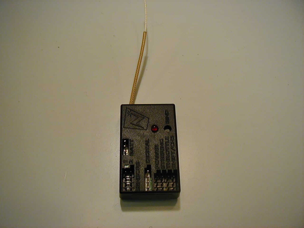
TSDNMD-AM03
Dec 01, 2005Remote Control Vehicle Transceiver Module
Equipment Class
DSS - Part 15 Spread Spectrum Transmitter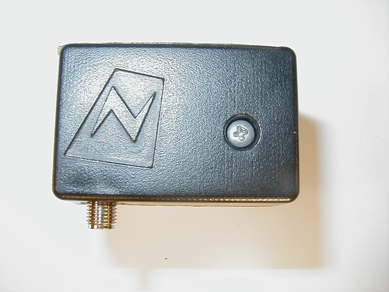
TSDNMD-AM02
Nov 15, 2005Digital R/C control system
Equipment Class
DTS - Digital Transmission System