TVRDSCS45Digital Still Camera
Hon Hai Precision Industry Co., Ltd. Nei-Hu Branch Office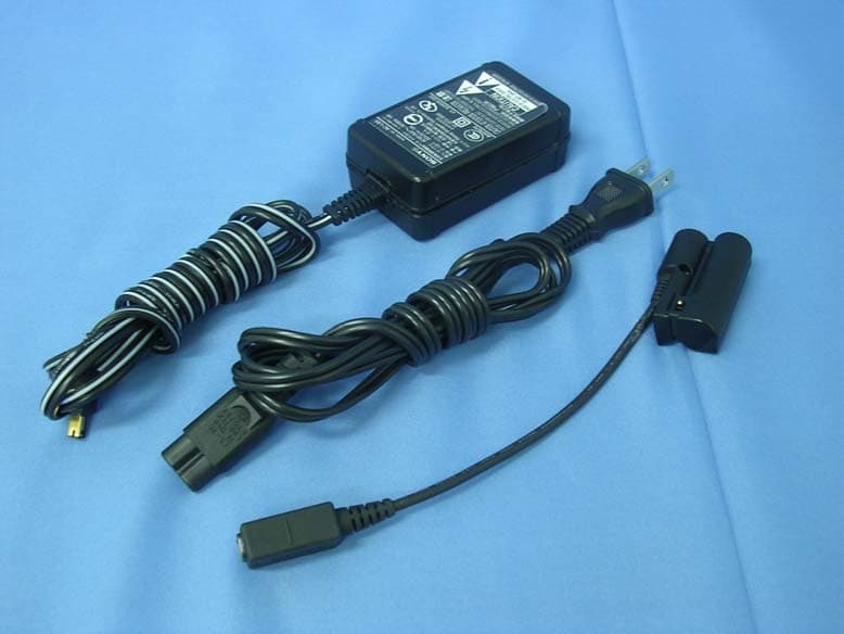
Click to zoom
Application Details
- Equipment Class
- JBP - Part 15 Class B Computing Device Peripheral
- Date of Grant
- Feb 24, 2006
- Application Purpose
- Original Equipment
- Date of Application
- Feb 23, 2006
- Equipment Note
- Digital Still Camera
- Country
- Taiwan
Documents & Files
Document Text
Text extracted from the exhibit documents filed with the FCC. Open a document above to read the original.
Users Manual
2-680-136-11(1) © 2006 Sony Corporation Digital Still Camera Cyber-shot Handbook Handbook Before operating the unit, please read this handbook and “Instruction Manual” (separate volume) thoroughly, and retain them for future reference. Owner’s Record The model and serial numbers are located on the bottom. Record the serial number in the space provided below. Refer to these numbers whenever you call upon your Sony dealer regarding this product. Model No. DSC-S45 Serial No. ___________________________ DSC-S45 “Instruction Manual” (separate volume) Explains the set-up and basic operations for shooting/playback with your camera. Instruction Manua l Digital Still Camera Enjoying the camera Using the menu Using the Setup screen Using your computer Printing still images Connecting your camera to your TV Troubleshooting Others Index 2 To reduce fire or shock hazard, do not expose the unit to rain or moisture. This device complies with part 15 of the FCC rules. Operation is subject to the following two conditions: (1) This device may not cause harmful interference, and (2) This device must accept any interference received, including interference that may cause undesired operation. CAUTION You are cautioned that any changes or modifications not expressly approved in this manual could void your authority to operate this equipment. Note: This equipment has been tested and found to comply with the limits for a Class B digital device, pursuant to Part 15 of the FCC Rules. These limits are designed to provide reasonable protection against harmful interference in a residential installation. This equipment generates, uses, and can radiate radio frequency energy and, if not installed and used in accordance with the instructions, may cause harmful interference to radio communications. However, there is no guarantee that interference will not occur in a particular installation. If this equipment does cause harmful interference to radio or television reception, which can be determined by turning the equipment off and on, the user is encouraged to try to correct the interference by one or more of the following measures: – Reorient or relocate the receiving antenna. – Increase the separation between the equipment and receiver. – Connect the equipment into an outlet on a circuit different from that to which the receiver is connected. – Consult the dealer or an experienced radio/TV technician for help. The supplied interface cable must be used with the equipment in order to comply with the limits for a digital device pursuant to Subpart B of Part 15 of FCC Rules. WARNING For Customers in the U.S.A. This symbol is intended to alert the user to the presence of uninsulated “dangerous voltage” within the product's enclosure that may be of sufficient magnitude to constitute a risk of electric shock to persons. This symbol is intended to alert the user to the presence of important operating and maintenance (servicing) instructions in the literature accompanying the appliance. 3 Notes on using your camera Types of “Memory Stick” that can be used (not supplied) The IC recording medium used by this camera is a “Memory Stick Duo”. There are two types of “Memory Stick”. “Memory Stick Duo”: you can use a “Memory Stick Duo” with your camera. “Memory Stick”: you cannot use a “Memory Stick” with your camera. Other memory cards cannot be used. • For details on “Memory Stick Duo”, see page 83. When using a “Memory Stick Duo” with “Memory Stick” compatible equipment You can use the “Memory Stick Duo” by inserting it into the Memory Stick Duo Adaptor (not supplied). Memory Stick Duo Adaptor No compensation for contents of the recording • The contents of the recording cannot be compensated for if recording or playback is not possible due to a malfunction of your camera or recording media, etc. Internal memory and “Memory Stick Duo” back up • Do not turn off the camera or remove the battery pack or “Memory Stick Duo” while the access lamp is lighted, as the internal memory data or “Memory Stick Duo” data may be destroyed. Always protect your data by making a back up copy. See page 22 for the data back up method. Notes on recording/playback • This camera is neither dust-proof, nor splash- proof, nor water-proof. Read “Precautions” (page 87) before operating the camera. • Before you record one-time events, make a trial recording to make sure that the camera is working correctly. • Be careful not to get the camera wet. Water entering the inside of the camera may cause malfunctions which in some cases may not be repairable. • Do not aim the camera at the sun or other bright light. This may cause irrecoverable damage to your eyes. Or it may cause the malfunction of your camera. • Do not use the camera near a location that generates strong radio waves or emits radiation. The camera may not be able to record or play back properly. • Using the camera in sandy or dusty locations may cause malfunctions. • If moisture condensation occurs, remove it before using the camera (page 87). • Do not shake or strike the camera. In addition to malfunctions and an inability to record images, this may render the recording medium unusable, or cause image data breakdown, damage or loss. • Clean the flash surface before use. The heat of flash emission may cause dirt on the flash surface to become discolored or to stick to the flash surface, resulting in insufficient light emission. Notes on the LCD screen and lens • The LCD screen is manufactured using extremely high-precision technology so over 99.4% of the pixels are operational for effective use. However, there may be some tiny black points and/or bright points (white, red, blue, or green in color) that constantly appear on the LCD screen. These points are normal in the manufacturing process and do not affect the recording in any way. Black, white, red, blue and green points 4 • Exposing the LCD screen or the lens to direct sunlight for long periods may cause malfunctions. Be careful when placing the came…
Text truncated - open the document above for the full version.
External Photos
Report No: 05CH066F Page: 35 of 57 Version:1.0 Attachement ¾ EUT Photograph (1) EUT Photo (2) EUT Photo Report No: 05CH066F Page: 36 of 57 Version:1.0 (3) EUT Photo (4) EUT Photo Report No: 05CH066F Page: 37 of 57 Version:1.0 (5) EUT Photo (6) EUT Photo
ID Label/Location Info
FCC ID.: TVRDSCS45 FCC ID AND DoC Label FCC ID.: TVRDSCS45
Internal Photos
Report No: 05CH066F Page: 38 of 57 Version:1.0 (7) EUT Photo (8) EUT Photo Report No: 05CH066F Page: 39 of 57 Version:1.0 (9) EUT Photo (10) EUT Photo Report No: 05CH066F Page: 40 of 57 Version:1.0 (11) EUT Photo (12) EUT Photo Report No: 05CH066F Page: 41 of 57 Version:1.0 (13) EUT Photo (14) EUT Photo Report No: 05CH066F Page: 42 of 57 Version:1.0 (15) EUT Photo (16) EUT Photo Report No: 05CH066F Page: 43 of 57 Version:1.0 (17) EUT Photo (18) EUT Photo Report No: 05CH066F Page: 44 of 57 Version:1.0 (19) EUT Photo Report No: 05CH066F Page: 45 of 57 Version:1.0 (20) EUT Photo Report No: 05CH066F Page: 46 of 57 Version:1.0 (21) EUT Photo Report No: 05CH066F Page: 47 of 57 Version:1.0 (22) EUT Photo (23) EUT Photo Report No: 05CH066F Page: 48 of 57 Version:1.0 (24) EUT Photo (25) EUT Photo Report No: 05CH066F Page: 49 of 57 Version:1.0 (26) EUT Photo (27) EUT Photo Report No: 05CH066F Page: 50 of 57 Version:1.0 (28) EUT Photo (29) EUT Photo Report No: 05CH066F Page: 51 of 57 Version:1.0 (30) EUT Photo (31) EUT Photo Report No: 05CH066F Page: 52 of 57 Version:1.0 (32) EUT Photo (33) EUT Photo Report No: 05CH066F Page: 53 of 57 Version:1.0 (34) EUT Photo (35) EUT Photo Report No: 05CH066F Page: 54 of 57 Version:1.0 (36) EUT Photo (37) EUT Photo Report No: 05CH066F Page: 55 of 57 Version:1.0 (38) EUT Photo (39) EUT Photo Report No: 05CH066F Page: 56 of 57 Version:1.0 (40) EUT Photo (41) EUT Photo Report No: 05CH066F Page: 57 of 57 Version:1.0 (42) EUT Photo
Operational Description
Report No: 05CH066F Page: 8 of 57 Version:1.0 1.5. EUT Exercise Software Test Mode Mode 1: USB Mode 1 Setup EUT and PC as shown on 1.4. 2 Transmit REC file with USB cable. Test Mode Mode 2: REC Mode 1 Setup EUT and PC as shown on 1.4. 2 Turn on the power of all equipment. 3 The lens of EUT was cover with black tape. 4 Press REC key. 5 Save black file. Test Mode Mode 3: Silde Show Mode 1 Setup EUT and PC as shown on 1.4. 2 Play REC file (black file).
Test Report
Report No: 05CH066F Page: 1 of 57 Version:1.0 Test Report Product Name:Digital Still Camera Model No. :DSC-S45 FCC ID. :TVRDSCS45 Applicant : PREMIER IMAGE TECHNOLOGY CORPORATION Address : 5F, No.9, LI-SHIN RD. V, SCIENCE-BASED INDUSTRIAL PARK, HSINCHU, TAIWAN, R.O.C. Date of Receipt:2005/12/20 Issued Date :2006/02/16 Report No. :05CH066F The test results relate only to the samples tested. The test report shall not be reproduced except in full without the written approval of QuieTek Corporation. Report No: 05CH066F Page: 2 of 57 Version:1.0 Test Report Certification Issued Date : 2006/02/16 Report No. : 05CH066F Product Name : Digital Still Camera Applicant : PREMIER IMAGE TECHNOLOGY CORPORATION Address : 5F, No.9, LI-SHIN RD. V, SCIENCE-BASED INDUSTRIAL PARK, HSINCHU, TAIWAN, R.O.C. Manufacturer : PREMIER IMAGE TECHNOLOGY CORPORATION Model No. : DSC-S45 FCC ID. : TVRDSCS45 Rated Voltage : AC 120 V / 60 Hz EUT Voltage : AC 120 V / 60 Hz Trade Name : SONY Applicable Standard : FCC CFR Title 47 Part 15 Subpart B: 2005 Class B, CISPR 22: 2005 Classification : B Test Result : Complied The test results relate only to the samples tested. The test report shall not be reproduced except in full without the written approval of QuieTek Corporation. This report must not be used to claim product endorsement by NVLAP any agency of the U.S. Government Documented By : ( Carol Tsai ) Tested By : ( Sean Liu ) Approved By : ( Bob Fang ) Report No: 05CH066F Page: 3 of 57 Version:1.0 TABLE OF CONTENTS Description Page 1. General Information ..................................................................................................... 4 1.1. EUT Description ............................................................................................................. 4 1.2. Test Mode .......................................................................................................................5 1.3. Tested System Details .................................................................................................... 6 1.4. Configuration of tested System ...................................................................................... 7 1.5. EUT Exercise Software .................................................................................................. 8 1.6. Test Facility..................................................................................................................... 9 2. Conducted Emission.................................................................................................. 10 2.1. Test Equipment............................................................................................................. 10 2.2. Test Setup .................................................................................................................... 10 2.3. Limits ............................................................................................................................ 11 2.4. Test Procedure ............................................................................................................. 11 2.5. Uncertainty ................................................................................................................... 11 2.6. Test Specification.......................................................................................................... 11 2.7. Test Result....................................................................................................................12 2.8. Test Photo .................................................................................................................... 18 3. Radiated Emission ..................................................................................................... 21 3.1. Test Equipment............................................................................................................. 21 3.2. Test Setup .................................................................................................................... 21 3.3. Limits ............................................................................................................................ 22 3.4. Test Procedure ............................................................................................................. 23 3.5. Uncertainty ................................................................................................................... 23 3.6. Test Specification.......................................................................................................... 23 3.7. Test Result....................................................................................................................24 3.8. Test Photo .................................................................................................................... 30 Attachement ......................................................................................................................................... 35 EUT Photograph........................................................................................................... 35 Report No: 05CH066F Page: 4 of 57 Version:1.0 1. General Information 1.1. EUT Description Product Name Digital Still Camera Trade Name SONY Model No. DSC-S45 Max Resolution 5.1Mega Pixels Component USB Cable Shielded, 1.5m, one ferrite core bonded. AV Cable Non-Shielded, 1.5m, one ferrite core bonded. Battery Cable Non-Shielded, 0.15m Power Adapter SONY, AC-LS5 Cable Out: Non-Shielded, 1.5m Power Cord: Non-Shielded, 1.5m Note: 1. This EUT is a Digital Still Camera. Report No: 05CH066F Page: 5 of 57 Version:1.0 1.2. Test Mode QuieTek has verified the construction and function in typical operation. All the test modes were carried out with the EUT in normal operation, which was shown in this test report and defined as: Pre-Test Mode EMI Mode 1: USB Mode Mode 2: REC Mode Mode 3: Silde Show Mode Final Test Mode EMI Mode 1: USB Mode Mode 2: REC Mode Mode 3: Silde S…
Text truncated - open the document above for the full version.
Test Setup Photos
Report No: 05CH066F Page: 18 of 57 Version:1.0 2.8. Test Photo Test Mode : Mode 1: USB Mode Description: Front View of Conducted Emission Test Setup Test Mode : Mode 1: USB Mode Description: Back View of Conducted Emission Test Setup Report No: 05CH066F Page: 19 of 57 Version:1.0 Test Mode : Mode 2: REC Mode Description: Front View of Conducted Emission Test Setup Test Mode : Mode 2: REC Mode Description: Back View of Conducted Emission Test Setup Report No: 05CH066F Page: 20 of 57 Version:1.0 Test Mode : Mode 3: Silde Show Mode Description: Front View of Conducted Emission Test Setup Test Mode : Mode 3: Silde Show Mode Description: Back View of Conducted Emission Test Setup Report No: 05CH066F Page: 30 of 57 Version:1.0 3.8. Test Photo Test Mode : Mode 1: USB Mode Description: Front View of Radiated Emission Test Setup Test Mode : Mode 1: USB Mode Description: Back View of Radiated Emission Test Setup Report No: 05CH066F Page: 31 of 57 Version:1.0 Test Mode : Mode 1: USB Mode Description: Front View of Radiated Emission Test Setup (Horn) Test Mode : Mode 2: REC Mode Description: Front View of Radiated Emission Test Setup Report No: 05CH066F Page: 32 of 57 Version:1.0 Test Mode : Mode 2: REC Mode Description: Back View of Radiated Emission Test Setup Test Mode : Mode 2: REC Mode Description: Front View of Radiated Emission Test Setup (Horn) Report No: 05CH066F Page: 33 of 57 Version:1.0 Test Mode : Mode 3: Silde Show Mode Description: Front View of Radiated Emission Test Setup Test Mode : Mode 3: Silde Show Mode Description: Back View of Radiated Emission Test Setup Report No: 05CH066F Page: 34 of 57 Version:1.0 Test Mode : Mode 3: Silde Show Mode Description: Front View of Radiated Emission Test Setup (Horn)
Contact Information
Applicant
MING-SHENG WEI(Engineer)
Technical Contact
QuieTek CorporationMicki Ho
[email protected]+886 2 8792 6808
2F, No. 345, Xinhu 2nd Rd · Taipei · Taiwan
Test Firm
DEKRA Testing and Certification Co., Ltd.Sky Hsu
Technical Specifications
| # | Rule Parts | Frequency Range | Power Output |
|---|---|---|---|
| 1 | 15B | - | - |
Other Applications from Hon Hai Precision Industry Co., Ltd. Nei-Hu Branch Office
TVR-RC380P1
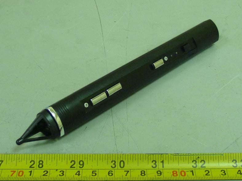
Oct 30, 2011Interactive pen
Equipment Class
DXX - Part 15 Low Power Communication Device Transmitter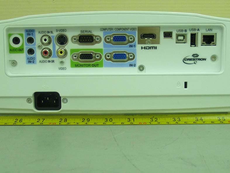
TVR-XD365UEST
Oct 30, 2011Data Projector
Equipment Class
DXX - Part 15 Low Power Communication Device Transmitter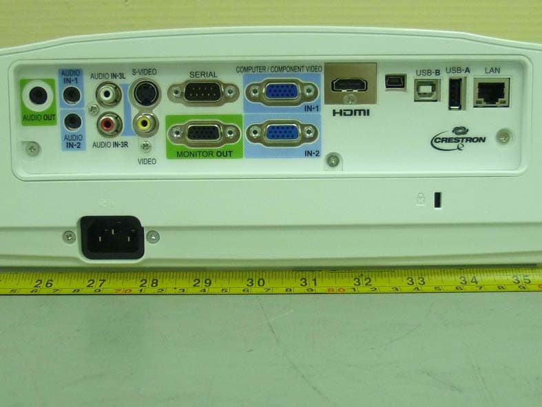
TVR-WD385UEST
Oct 27, 2011Data Projector
Equipment Class
DXX - Part 15 Low Power Communication Device Transmitter
TVRDSCS780
Dec 24, 2007Digital Still Camera
Equipment Class
JBP - Part 15 Class B Computing Device Peripheral
TVRDSCS730
Sep 09, 2007Digital Still Camera
Equipment Class
JBP - Part 15 Class B Computing Device Peripheral