TVRDSCS700Digital Still Camera
Hon Hai Precision Industry Co., Ltd. Nei-Hu Branch Office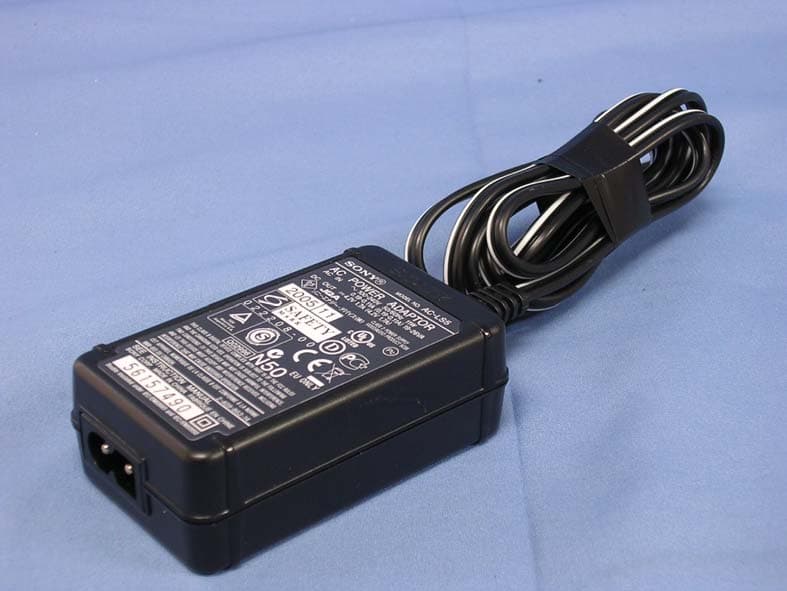
Click to zoom
Application Details
- Equipment Class
- JBP - Part 15 Class B Computing Device Peripheral
- Date of Grant
- Dec 22, 2006
- Application Purpose
- Original Equipment
- Date of Application
- Dec 20, 2006
- Equipment Note
- Digital Still Camera
- Country
- Taiwan
Documents & Files
Document Text
Text extracted from the exhibit documents filed with the FCC. Open a document above to read the original.
Users Manual
DSC-S650/S700 2-897-955-12(1) G:\SONY\PvPi\Cy- ber\E\XXXXXXXX_CX60050_60_Paper_Rev\1201\2897955111\2897955111DSCS650CA2\01G B-DSCS650\010COV.fm master:Right © 2007 Sony Corporation2-897-955-12(1) Instruction Manual DSC-S650/S700 Digital Still Camera Operating Instructions Before operating the unit, please read this manual thoroughly, and retain it for future reference. For details on the advanced operations, please access “Cyber-shot Handbook”contained on the supplied CD-ROM via a computer. GB 2897955121.p.pdf 112/4/2006 9:40:21 AM 2 DSC-S650/S700 2-897-955-12(1) G:\SONY\PvPi\Cy- ber\E\XXXXXXXX_CX60050_60_Paper_Rev\1201\2897955111\2897955111DSCS650CA2\01G B-DSCS650\020REG.fm master:Left_Safety Owner’s Record The model and serial numbers are located on the bottom. Record the serial number in the space provided below. Refer to these numbers whenever you call upon your Sony dealer regarding this product. Model No. DSC-S650/S700 Serial No. ______________________________ To reduce fire or shock hazard, do not expose the unit to rain or moisture. IMPORTANT SAFEGUARDS For your protection, please read these safety instructions completely before operating the appliance, and keep this manual for future reference. Carefully observe all warnings, precautions and instructions on the appliance, or the one described in the operating instructions and adhere to them. [Power Sources This set should be operated only from the type of power source indicated on the marking label. If you are not sure of the type of electrical power supplied to your home, consult your dealer or local power company. For those sets designed to operate from battery power, or other sources, refer to the operating instructions. [Polarization This set may be equipped with a polarized ac power cord plug (a plug having one blade wider than the other). This plug will fit into the power outlet only one way. This is a safety feature. If you are unable to insert the plug fully into the outlet, try reversing the plug. If the plug should still fail to fit, contact your electrician to have a suitable outlet installed. Do not defeat the safety purpose of the polarized plug by forcing it in. [Overloading Do not overload wall outlets, extension cords or convenience receptacles beyond their capacity, since this can result in fire or electric shock. [Object and Liquid Entry Never push objects of any kind into the set through openings as they may touch dangerous voltage points or short out parts that could result in a fire or electric shock. Never spill liquid of any kind on the set. [Attachments Do not use attachments not recommended by the manufacturer, as they may cause hazards. WARNING For Customers in the U.S.A. This symbol is intended to alert the user to the presence of uninsulated “dangerous voltage” within the product's enclosure that may be of sufficient magnitude to constitute a risk of electric shock to persons. This symbol is intended to alert the user to the presence of important operating and maintenance (servicing) instructions in the literature accompanying the appliance. Use 2897955121.p.pdf 212/4/2006 9:40:22 AM 3 DSC-S650/S700 2-897-955-12(1) G:\SONY\PvPi\Cy- ber\E\XXXXXXXX_CX60050_60_Paper_Rev\1201\2897955111\2897955111DSCS650CA2\01G B-DSCS650\020REG.fm master:Right [Cleaning Unplug the set from the wall outlet before cleaning or polishing it. Do not use liquid cleaners or aerosol cleaners. Use a cloth lightly dampened with water for cleaning the exterior of the set. [Water and Moisture Do not use power-line operated sets near water – for example, near a bathtub, washbowl, kitchen sink, or laundry tub, in a wet basement, or near a swimming pool, etc. [Power-Cord Protection Route the power cord so that it is not likely to be walked on or pinched by items placed upon or against them, paying particular attention to the plugs, receptacles, and the point where the cord exits from the appliance. [Accessories Do not place the set on an unstable cart, stand, tripod, bracket, or table. The set may fall, causing serious injury to a child or an adult, and serious damage to the set. Use only a cart, stand, tripod, bracket, or table recommended by the manufacturer. [Ventilation The slots and openings in the cabinet are provided for necessary ventilation. To ensure reliable operation of the set, and to protect it from overheating, these slots and openings must never be blocked or covered. – Never cover the slots and openings with a cloth or other materials. – Never block the slots and openings by placing the set on a bed, sofa, rug, or other similar surface. – Never place the set in a confined space, such as a bookcase, or built-in cabinet, unless proper ventilation is provided. – Do not place the set near or over a radiator or heat register, or where it is exposed to direct sunlight. [Lightning For added protection for this set during a lightning storm, or when it is left unattended and unused for long periods of time, unplug it from the wall outlet and disconnect the antenna or cable system. This will prevent damage to the set due to lightning and power-line surges. [Damage Requiring Service Unplug the set from the wall outlet and refer servicing to qualified service personnel under the following conditions: – When the power cord or plug is damaged or frayed. – If liquid has been spilled or objects have fallen into the set. – If the set has been exposed to rain or water. – If the set has been subject to excessive shock by being dropped, or the cabinet has been damaged. – If the set does not operate normally when following the operating instructions. Adjust only those controls that are specified in the operating instructions. Improper adjustment of other controls may result in damage and will often require extensive work by a qualified technician to restore the set to normal operation. – When the set exhibits a distinct change in performance – this indicates a need for service. [Servicing Do not attempt to service the set yourself as openin…
Text truncated - open the document above for the full version.
Block Diagram
5 5 4 4 3 3 2 2 1 1 DD CC BB AA MLCD_ON STROBE_Chg +13.5V -7.5V STROBE_Trg HD VD CCD[0..11] SDATA FOCUS_M1 FOCUS_M2 FOCUS_M0 IRIS_M0 FOCUS_M3 ZOOM_M0 IRIS_M1 Shutter_M1 LCD[0..7] +5VM Charge_c FLASH_RDY DGND +12V ZOOM FOCUS IRIS SHUTTER ZPR_PWR ZOOM_PR ZOOM_PI ZPI_PWR RAMLDM RAMCAS RAMA[0..14] RAMWE_N RAMUDQS RAMREF RAMCS_N RAMRAS RAMUDM RAMCLK_N RAMCLK_EN RAMCLK RAMLDQS PXCLK SCLK VSUB_Con2 CDS_EN TG_EN AFERST VSUB_Con1 ALE R/B CLE WE CE0 RE FA21 FA22 FA23 FPI_PWR FOCUS_PI RAMD[0..15] LINE_OUT AV_DET BEEPER VIDEO_OUT PW_LED MODE_R0 ~R5 SHUT1,2 D+ D- FD[0..7] +3.3VD DGND +2.5V +13V CCD_ON +13.5V PWR_CTRL CCD_ON +2.5V ZOOM_M1 +5VM DGND +3.3VD +3.3VD +3.1V_TG +3.1V_CDS +1.8VD TELE WIDE +3.3VD DGND BAT_LOAD MIC MIC_N +3.3VD DGND MS_CLK FA20 +3.3VD MS_INS# LCD_HD LCD_VD LCD_EN LCD_MCLK LCD_SCLK LCD_SDATA +3.1VL+3.3VD MLCD_ON DGND +5VM LED- WP +3.3VD DGND +3.3VS VP VP USB_DET TG_ON -7.5V_VD +13V_VD CSUB +13V_CCD -7.5V_CCD CSUB +3.1V Shutter_M0 MOTOR_PS PWR_KEY FLASH_Chg_L VP DGND BL VP +5VM DGND STROBE_Trg Charge_c FLASH_RDY STROBE_Chg PWR_ON PWRKEY +3.3VS SHUT2 PW_LED MODE_R4 MODE_R1 MODE_R0 MODE_R2-3 SHUT1 MODE_R5 +3.3VD DGND TRASH MS_LED DOWN DGND +3.3VDMS_LED RIGHT UP LEFT SET MENU DISPLAY VP H1A H2A H1B H2B CSUB CCD_OUT -7.5V_CCD VIA,VIB ~V4,V2 +13V_CCD VHLD VSUB SUB CCD_OUT +13V_CCD RG OFFPAGELEFT-R Title SizeDocument NumberRev Date:Sheetof WS01D 11Wednesday, August 23, 2006 Title SizeDocument NumberRev Date:Sheetof WS01D 11Wednesday, August 23, 2006 Title SizeDocument NumberRev Date:Sheetof WS01 DSC-S700 BLOCK DIAGAM D 11Wednesday, August 23, 2006 ZOOM MOTOR FOCUS MOTOR IRIS MOTOR SHUTTER MOTOR FOCUS SENSOR ZOOM SENSOR LCD_BACKLIGHT AUO LCD 2.0 INCH PANEL TV PC SDC7370 OVERALL BLOCK DIAGRAM BUFFER 34 PIN B TO B 1 2 CONN WIRE 2PCONN WIRE 2P CDS CCD[0..11] VD HD SCLK PXCLK AFERST SDATA CDS_EN TG_EN +3.1V +3.1V_CDS +3.1V_TG -7.5V_VD +13V_VD 1 42 3 NC S P1,P2 S P1,P2 FLASH_Chg_L STROBE_Chg Charge_c STROBE_Trg FLASH_RDY VP +5VM DGND 12 13 2 12 3 1 4 25 6 12 12 GREENGREEN 12 12 REDRED 41 32 12 GREENGREEN LCD_EN LCD_MCLK LCD_HD LCD_SCLK LCD_SDATA LCD_VD LCD[0..7] +3.1VL LED- DGND +5VM BL DSP RAMD[0..15] RAMA[0..14] RAMCS_N RAMUDQS ALE CLE WE RE WP BAT_LOAD CE0 R/B CCD[0..11] VD HD CDS_EN TG_EN RAMREF RAMLDM RAMCAS RAMWE_N RAMRAS RAMUDM FOCUS_PI ZOOM_PR SHUT1 ZOOM_PI STROBE_Trg FOCUS_M0 FOCUS_M1 FOCUS_M2 FOCUS_M3 ZOOM_M0 ZOOM_M1 LCD_HD LCD_VD VIDEO_OUT MOTOR_PS Shutter_M1 Shutter_M0 IRIS_M1 IRIS_M0 BEEPER LCD_MCLK LCD[0..7] ZPI_PWR PWR_CTRL D- D+ DGND +3.3VD +1.8VD LCD_EN MD[0..7] SHUT2 VP LCD_SCLK LCD_SDATA CCD_ON Charge_c ZPR_PWR FPI_PWR RAMCLK_N RAMCLK RAMCLK_EN RAMLDQS FLASH_RDY MLCD_ON MODE_R0 MODE_R1 MODE_R2-3 LINE_OUT +2.5V FLASH_chg_L AFERST STROBE_chg WIDE MODE_R4 MODE_R5 MS_INS# AV_DET MS_CLK TELE USB_DET FA20 FA21 FA22 FA23 DOWN PW_LED BL TRASH LEFT RIGHT PXCLK DISPLAY UP SET MENU SCLK VSUB_Con1 VSUB_Con2 SDATA MS_LED +3.3VS TG_ON PWRKEY PWR_ON MIC MIC_N ALE DGNDDGND D+ USB_DET D- +3.3VD DGND A/V_DET VIDEO_OUT LINE_OUT CCD CSUB -7.5V_CCD +15V_CCD MS CARD1 MS_INS# FA20 FA21 MS_CLK FA22 FA23 ALE +3.3VD DGND NAND FLASH1 CLE WE WP ALE CE0 RE R/B MD[0..7] +3.3VD DGND MOTOR DRIVER MOTOR_PS ZOOM_M1 ZOOM_M0 FOCUS_M1 FOCUS_M0 FOCUS_M3 FOCUS_M2 IRIS_M0 IRIS_M1 Shutter_M1 Shutter_M0 +5VM DGND +3.3VD LEFT RIGHT UP DOWN MENU DISPLAY TRASH SET MS_LED +3.3VD DGND 1 2 MODE_R5 MODE_R4 MODE_R2-3 MODE_R1 MODE_R0 SHUT1 SHUT2 PW_LED PWR_KEY +3.3VD DGND 1 2 12 12 POWER +2.5V +1.8V CCD_ON PWRCTRL +5VM +3.3VD VP +12V DGND -7.5VMLCD_ON +13.5V VBATVBAT DDR RAMD[0..15] RAMA[0..14] RAMLDM RAMWE_N RAMCAS RAMRAS RAMCS_N RAMLDQS RAMUDQS RAMUDM RAMCLK_N RAMCLK RAMCLK_EN RAMREF DGND +2.5V 3 1 4 25 6
External Photos
Report No: 06CH036-IT-US-P01V02 Page: 47 of 78 5. Attachment ¾ EUT Photograph (1) EUT Photo (2) EUT Photo Report No: 06CH036-IT-US-P01V02 Page: 48 of 78 (3) EUT Photo (4) EUT Photo Report No: 06CH036-IT-US-P01V02 Page: 49 of 78 (5) EUT Photo (6) EUT Photo Report No: 06CH036-IT-US-P01V02 Page: 50 of 78 (7) EUT Photo (8) EUT Photo Report No: 06CH036-IT-US-P01V02 Page: 51 of 78 (9) EUT Photo (10) EUT Photo Report No: 06CH036-IT-US-P01V02 Page: 52 of 78 (11) EUT Photo (12) EUT Photo
ID Label/Location Info
Hon Hai Precision Industry Co., Ltd. Nei-Hu Branch Office 1~11 F., No.32, Ji-hu Rd., Nei-hu, Taipei 114, Taiwan, R.O.C. FCC ID.: TVRDSCS700 FCC ID AND DoC Label Hon Hai Precision Industry Co., Ltd. Nei-Hu Branch Office 1~11 F., No.32, Ji-hu Rd., Nei-hu, Taipei 114, Taiwan, R.O.C. FCC ID.: TVRDSCS700
Internal Photos
Report No: 06CH036-IT-US-P01V02 Page: 53 of 78 (13) EUT Photo (14) EUT Photo Report No: 06CH036-IT-US-P01V02 Page: 54 of 78 (15) EUT Photo (16) EUT Photo Report No: 06CH036-IT-US-P01V02 Page: 55 of 78 (17) EUT Photo (18) EUT Photo Report No: 06CH036-IT-US-P01V02 Page: 56 of 78 (19) EUT Photo (20) EUT Photo Report No: 06CH036-IT-US-P01V02 Page: 57 of 78 (21) EUT Photo (22) EUT Photo Report No: 06CH036-IT-US-P01V02 Page: 58 of 78 (23) EUT Photo (24) EUT Photo Report No: 06CH036-IT-US-P01V02 Page: 59 of 78 (25) EUT Photo (26) EUT Photo Report No: 06CH036-IT-US-P01V02 Page: 60 of 78 (27) EUT Photo (28) EUT Photo Report No: 06CH036-IT-US-P01V02 Page: 61 of 78 (29) EUT Photo (30) EUT Photo Report No: 06CH036-IT-US-P01V02 Page: 62 of 78 (31) EUT Photo Report No: 06CH036-IT-US-P01V02 Page: 63 of 78 (32) EUT Photo Report No: 06CH036-IT-US-P01V02 Page: 64 of 78 (33) EUT Photo (34) EUT Photo Report No: 06CH036-IT-US-P01V02 Page: 65 of 78 (35) EUT Photo (36) EUT Photo
Internal Photos
Report No: 06CH036-IT-US-P01V02 Page: 66 of 78 (37) EUT Photo (38) EUT Photo Report No: 06CH036-IT-US-P01V02 Page: 67 of 78 (39) EUT Photo (40) EUT Photo Report No: 06CH036-IT-US-P01V02 Page: 68 of 78 (41) EUT Photo (42) EUT Photo Report No: 06CH036-IT-US-P01V02 Page: 69 of 78 (43) EUT Photo (44) EUT Photo Report No: 06CH036-IT-US-P01V02 Page: 70 of 78 (45) EUT Photo (46) EUT Photo Report No: 06CH036-IT-US-P01V02 Page: 71 of 78 (47) EUT Photo (48) EUT Photo Report No: 06CH036-IT-US-P01V02 Page: 72 of 78 (49) EUT Photo (50) EUT Photo Report No: 06CH036-IT-US-P01V02 Page: 73 of 78 (51) EUT Photo (52) EUT Photo Report No: 06CH036-IT-US-P01V02 Page: 74 of 78 (53) EUT Photo (54) EUT Photo Report No: 06CH036-IT-US-P01V02 Page: 75 of 78 (55) EUT Photo (56) EUT Photo Report No: 06CH036-IT-US-P01V02 Page: 76 of 78 (57) EUT Photo (58) EUT Photo Report No: 06CH036-IT-US-P01V02 Page: 77 of 78 (59) EUT Photo (60) EUT Photo Report No: 06CH036-IT-US-P01V02 Page: 78 of 78 (61) EUT Photo (62) EUT Photo
Operational Description
Report No: 06CH036-IT-US-P01V02 Page: 10 of 78 1.5. EUT Exercise Software Test Mode Mode 1: Slide Show 1 Setup EUT and PC as shown on 1.4. 2 Play REC file (black loop). 3 Turn on the power. 4 Select play key. 5 Press MENU. 6 Press left key to select play OK. 7 Select START OK. 8 Show word of slide show on LCD display. 9 Test. Test Mode Mode 2: REC 1 Setup EUT and PC as shown on 1.4. 2 The lens of EUT was covered with black tape. 3 Turn on the power of all equipment. 4 Press REC key. 5 Save black file. Test Mode Mode 3: USB LCD on 1 Setup EUT and PC as shown on 1.4. 2 Loop transmit REC file with USB cable. 3 Turn on the power. 4 Write DSC file to PC for example. Test Mode Mode 4: Preview 1 Setup EUT and PC as shown on 1.4. 2 The lens of EUT was covered with black tape. 3 Turn on the power of all equipment. 4 Select capture preview mode. 5 Test.
Test Report
Test Report Product Name : Digital Still Camera Model No. : DSC-S700 FCC ID : TVRDSCS700 Applicant : Hon Hai Precision Industry Co., Ltd. Nei-Hu Branch Office Address : 1~11 F., No.32, Ji-hu Rd., Nei-hu, Taipei 114, Taiwan, R.O.C. Date of Receipt : 2006/12/06 Issued Date : 2006/12/14 Report No. : 06CH036-IT-US-P01V02 The test results relate only to the samples tested. The test results shown in the test report are traceable to the national/international standard through the calibration of the equipment and evaluated measurement uncertainty herein. This report must not be used to claim product endorsement by CNLA, NVLAP, NIST or any agency of the Government. The test report shall not be reproduced except in full without the written approval of QuieTek Corporation. Report No: 06CH036-IT-US-P01V02 Page: 2 of 78 Test Report Certification Issued Date : 2006/12/14 Report No. : 06CH036-IT-US-P01V02 Product Name : Digital Still Camera Applicant : Hon Hai Precision Industry Co., Ltd. Nei-Hu Branch Office Address : 1~11 F., No.32, Ji-hu Rd., Nei-hu, Taipei 114, Taiwan, R.O.C. Manufacturer : Hon Hai Precision Industry Co., Ltd. Nei-Hu Branch Office Model No. : DSC-S700 Rated Voltage : AC 120 V / 60 Hz EUT Voltage : AC 120 V / 60 Hz Trade Name : SONY Applicable Standard : FCC CFR Title 47 Part 15 Subpart B: 2005 Class B, CISPR 22: 2005 Test Result : Complied Performed Location : Hsinchu EMC Laboratory N0. 75-2, 3rd Lin, Wangye Keng, Yonghxing Tsuen, Qionglin Shiang, Hsinchu County 307, Taiwan, R.O.C. TEL:+886-3-592-8858 / FAX:+886-3-592-8859 Documented By : ( Carol Tsai ) Reviewed By : ( Winson Wu ) Approved By : ( Arthur Liu ) Report No: 06CH036-IT-US-P01V02 Page: 3 of 78 Laboratory Information We , QuieTek Corporation, are an independent EMC and safety consultancy that was established the whole facility in our laboratories. The test facility has been accredited by the following accreditation Bodies in compliance with ISO 17025, EN 45001 and Guide 25: The related certificate for our laboratories about the test site and management system can be downloaded from QuieTek Corporation’s Web Site : http://tw.quietek.com/modules/myalbum/ The address and introduction of QuieTek Corporation’s laboratories can be founded in our Web site : http://www.quietek.com/ If you have any comments, Please don’t hesitate to contact us. Our contact information is as below: HsinChu Testing Laboratory : No.75-2, 3rd Lin, Wangye Keng, Yonghxing Tsuen, Qionglin Shiang, Hsinchu County 307, Taiwan, R.O.C. TEL:+886-3-592-8858 / FAX:+886-3-592-8859 E-Mail : [email protected] LinKou Testing Laboratory : No. 5, Ruei-Shu Valley, Ruei-Ping Tsuen, Lin-Kou Shiang, Taipei, Taiwan, R.O.C. TEL : 886-2-8601-3788 / FAX : 886-2-8601-3789 E-Mail : [email protected] Taiwan R.O.C. : BSMI, DGT, CNLA Germany : TUV Rheinland Norway : Nemko, DNV USA : FCC, NVLAP Japan : VCCI 0914 1313 Report No: 06CH036-IT-US-P01V02 Page: 4 of 78 TABLE OF CONTENTS Description Page 1. General Information ................................................................................................................. 5 1.1. EUT Description ............................................................................................................... 5 1.2. Mode of Operation ........................................................................................................... 6 1.3. Tested System Details...................................................................................................... 7 1.4. Configuration of Tested System ....................................................................................... 8 1.5. EUT Exercise Software .................................................................................................. 10 2. Technical Test......................................................................................................................... 11 2.1. Summary of Test Result ................................................................................................. 11 2.2. List of Test Equipment .................................................................................................... 11 2.3. Measurement Uncertainty .............................................................................................. 12 2.4. Test Environment ........................................................................................................... 12 3. Conducted Emission ..............................................................................................................13 3.1. Test Specification ........................................................................................................... 13 3.2. Test Setup ......................................................................................................................13 3.3. Limit................................................................................................................................ 13 3.4. Test Procedure ............................................................................................................... 14 3.5. Test Result .....................................................................................................................15 3.6. Test Photograph ............................................................................................................. 19 4. Radiated Emission ................................................................................................................. 20 4.1. Test Specification ........................................................................................................... 20 4.2. Test Setup ......................................................................................................................20 4.3. Limit................................................................................................................................ 21 4.4. Test Procedure .........................................................…
Text truncated - open the document above for the full version.
Test Setup Photos
Report No: 06CH036-IT-US-P01V02 Page: 19 of 78 3.6. Test Photograph Test Mode : Mode 3: USB LCD on Description : Front View of Conducted Emission Test Setup Test Mode : Mode 3: USB LCD on Description : Back View of Conducted Emission Test Setup Report No: 06CH036-IT-US-P01V02 Page: 39 of 78 4.6. Test Photograph Test Mode : Mode 1: Slide Show Description : Front View of Radiated Emission Test Setup Test Mode : Mode 1: Slide Show Description : Back View of Radiated Emission Test Setup Report No: 06CH036-IT-US-P01V02 Page: 40 of 78 Test Mode : Mode 1: Slide Show Description : Front View of Radiated Emission Test Setup (Horn) Test Mode : Mode 1: Slide Show Description : Back View of Radiated Emission Test Setup (Horn) Report No: 06CH036-IT-US-P01V02 Page: 41 of 78 Test Mode : Mode 2: REC Description : Front View of Radiated Emission Test Setup Test Mode : Mode 2: REC Description : Back View of Radiated Emission Test Setup Report No: 06CH036-IT-US-P01V02 Page: 42 of 78 Test Mode : Mode 2: REC Description : Front View of Radiated Emission Test Setup (Horn) Test Mode : Mode 2: REC Description : Back View of Radiated Emission Test Setup (Horn) Report No: 06CH036-IT-US-P01V02 Page: 43 of 78 Test Mode : Mode 3: USB LCD on Description : Front View of Radiated Emission Test Setup Test Mode : Mode 3: USB LCD on Description : Back View of Radiated Emission Test Setup Report No: 06CH036-IT-US-P01V02 Page: 44 of 78 Test Mode : Mode 3: USB LCD on Description : Front View of Radiated Emission Test Setup (Horn) Test Mode : Mode 3: USB LCD on Description : Back View of Radiated Emission Test Setup (Horn) Report No: 06CH036-IT-US-P01V02 Page: 45 of 78 Test Mode : Mode 4: Preview Description : Front View of Radiated Emission Test Setup Test Mode : Mode 4: Preview Description : Back View of Radiated Emission Test Setup Report No: 06CH036-IT-US-P01V02 Page: 46 of 78 Test Mode : Mode 4: Preview Description : Front View of Radiated Emission Test Setup (Horn) Test Mode : Mode 4: Preview Description : Back View of Radiated Emission Test Setup (Horn)
Contact Information
Applicant
MING-SHENG WEI(Engineer)
Technical Contact
QuieTek CorporationMiki Ho
[email protected]886 2 8792 6808
2f, no 354, Xinhu 2nd Road. NeHu District · Taipei · Taiwan
Test Firm
QuieTek CorporationKevin (Yu-Lung) Chen
Technical Specifications
| # | Rule Parts | Frequency Range | Power Output |
|---|---|---|---|
| 1 | 15B | - | - |
Other Applications from Hon Hai Precision Industry Co., Ltd. Nei-Hu Branch Office
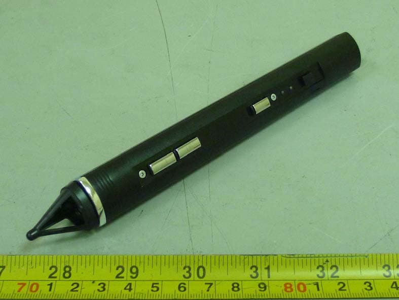
TVR-RC380P1
Oct 30, 2011Interactive pen
Equipment Class
DXX - Part 15 Low Power Communication Device Transmitter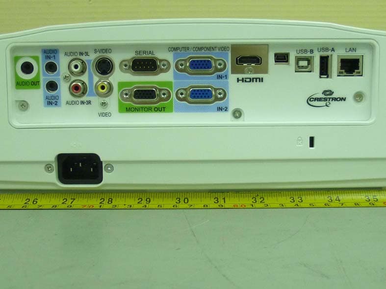
TVR-XD365UEST
Oct 30, 2011Data Projector
Equipment Class
DXX - Part 15 Low Power Communication Device Transmitter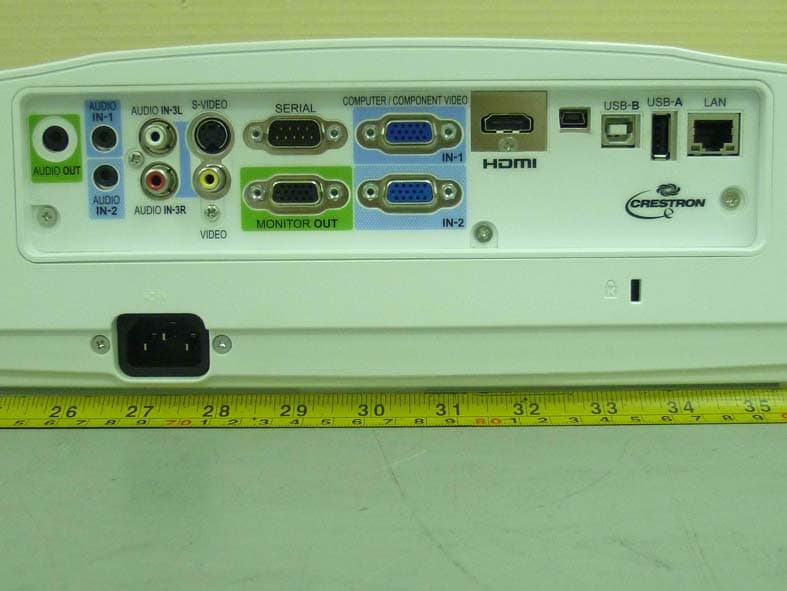
TVR-WD385UEST
Oct 27, 2011Data Projector
Equipment Class
DXX - Part 15 Low Power Communication Device Transmitter
TVRDSCS780
Dec 24, 2007Digital Still Camera
Equipment Class
JBP - Part 15 Class B Computing Device Peripheral
TVRDSCS730
Sep 09, 2007Digital Still Camera
Equipment Class
JBP - Part 15 Class B Computing Device Peripheral