TVRDSCS800Digital Still Camera
Hon Hai Precision Industry Co., Ltd. Nei-Hu Branch Office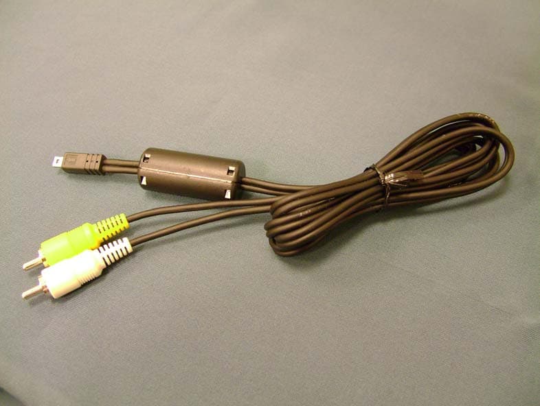
Click to zoom
Application Details
- Equipment Class
- JBP - Part 15 Class B Computing Device Peripheral
- Date of Grant
- Mar 06, 2007
- Application Purpose
- Original Equipment
- Date of Application
- Mar 06, 2007
- Equipment Note
- Digital Still Camera
- Country
- Taiwan
Documents & Files
Document Text
Text extracted from the exhibit documents filed with the FCC. Open a document above to read the original.
Users Manual
© 2007 Sony Corporation3-198-860-11(1) Digital Still Camera Cyber-shot Handbook DSC-S800 Before operating the unit, please read this Handbook and “Instruction Manual” and “Cyber-shot Step-up Guide” thoroughly, and retain them for future reference. Table of contents Basic Operations Using the menu Using the Setup screen Viewing images on a TV screen Using your computer Printing still images Troubleshooting Others Index VCLICK! GB 2 Notes on using your camera Types of “Memory Stick” that can be used (not supplied) The IC recording medium used by this camera is a “Memory Stick Duo”. There are two types of “Memory Stick”. “Memory Stick Duo”: you can use a “Memory Stick Duo” with your camera. “Memory Stick”: you cannot use a “Memory Stick” with your camera. Other memory cards cannot be used. • For details on “Memory Stick Duo”, see page 98. When using a “Memory Stick Duo” with “Memory Stick” compatible equipment You can use the “Memory Stick Duo” by inserting it into the Memory Stick Duo Adaptor (not supplied). Memory Stick Duo Adaptor Notes on the Nickel-Metal Hydride battery • Charge both of the Ni-MH batteries (supplied) before using the camera for the first time. • The batteries can be charged even if they are not completely discharged. Also, even if batteries are not fully charged, you can use the partially charged capacity of the batteries as is. • If you do not intend to use the batteries for a long time, use up the existing charge and remove them from your camera, then store them in a cool, dry place. This is to maintain the batteries’ functions (page 100). • For details on the usable batteries, see page 100. Notes on the LCD screen and lens • The LCD screen is manufactured using extremely high-precision technology so over 99.99% of the pixels are operational for effective use. However, there may be some tiny black points and/or bright points (white, red, blue or green in color) that constantly appear on the LCD screen. These points are normal in the manufacturing process and do not affect the recording in any way. • Exposing the LCD screen or the lens to direct sunlight for long periods may cause malfunctions. Be careful when placing the camera near a window or outdoors. • Do not press against the LCD screen. The screen may be discolored and that may cause a malfunction. • Images may trail across on the LCD screen in a cold location. This is not a malfunction. • This camera is equipped with a power zoom lens. Be careful not to bump the lens, and be careful not to apply force to it. The pictures used in this Handbook The photographs used as examples of pictures in this Handbook are reproduced images, and are not actual images shot using this camera. Black, white, red, blue or green points 3 Table of contents Notes on using your camera .....................................................................2 Basic techniques for better images ...........................................................6 Focus – Focusing on a subject successfully..................................................... 6 Exposure – Adjusting the light intensity ............................................................ 7 Color – On the effects of lighting ....................................................................... 8 Quality – On “image quality” and “image size” ................................................. 9 Identifying parts.......................................................................................10 Indicators on the screen ..........................................................................12 Changing the screen display ...................................................................16 Using the internal memory ......................................................................17 Using the mode dial.................................................................................18 Shooting images easily (Auto adjustment mode) ....................................19 Shooting still images (Scene selection)...................................................25 Viewing/deleting images..........................................................................28 Using menu items..............................................................................30 Menu items..........................................................................................31 Shooting menu ........................................................................................32 COLOR (Color Mode): Changing the vividness of the image or adding special effects (Metering Mode): Selecting the metering mode WB (White Bal): Adjusting the color tones ISO: Selecting a luminous sensitivity (P.Quality): Selecting the still image quality Mode (REC Mode): Selecting the continuous shooting method (Flash Level): Adjusting the amount of flash light (Sharpness): Adjusting the sharpness of the image (Setup): Changing Setup items Basic Operations Using the menu 4 Table of contents Viewing menu ......................................................................................... 39 (Folder): Selecting the folder for viewing images - (Protect): Preventing accidental erasure DPOF: Adding a Print order mark (Print): Printing images using a printer (Slide): Playing back a series of images (Resize): Changing the image size of a recorded image (Rotate): Rotating a still image (Setup): Changing Setup items Trimming: Rotating an enlarged image Using Setup items.............................................................................. 46 Camera .............................................................................................. 47 Internal Memory Tool ......................................................................... 50 Format Memory Stick Tool ............................................................................. 51 Setup 1............................................................................................... 54 Setup 2.............................................................…
Text truncated - open the document above for the full version.
Users Manual
54 For details on the operation 1 page 46 Setup 1 1 The default settings are marked with . Selects the brightness of the LCD backlight when using the camera with batteries. • You can change the setting by pressing DISP button longer. • Selecting [Bright] uses up the battery charge faster. Selects the sound produced when you operate the camera. Selects the language to be used to display the menu items, warnings, and messages. Initializes the setting to the default setting. Images stored in the internal memory are retained. 1Select [OK] with v on the control button, then press z. The message “Initialize all settings Ready?” appears. 2Select [OK] with v, then press z. The settings are reset to the default setting. To cancel the resetting Select [Cancel] in step 1 or 2, then press z. • Make sure that the power is not disconnected during resetting. LCD Backlight Bright Brightens Normal Beep Shutter Turns on the shutter sound when you press the shutter button. On Turns on the beep/shutter sound when you press the control button/ press the shutter button. Off Turns off the beep/shutter sound. Language Initialize 55 For details on the operation 1 page 46 Using the Setup screen Setup 2 2 The default settings are marked with . Selects the method used to assign file numbers to images. Selects the USB mode to be used when connecting the camera to a computer or a PictBridge compliant printer using the dedicated USB cable. File Number Series Assigns numbers to files in sequence even if the recording folder or the “Memory Stick Duo” is changed. (When the replaced “Memory Stick Duo” contains a file with a number higher than the last assigned number, a number one higher than the largest number is assigned.) Reset Starts from 0001 each time the folder is changed. (When the recording folder contains a file, a number one higher than the largest number is assigned.) USB Connect PictBridge Connects the camera to a PictBridge compliant printer (page 79). PTP When [PTP] (Picture Transfer Protocol) is set and the camera is connected to a computer, the images in the recording folder on the camera are copied to the computer. (Compatible with Windows XP and Mac OS X.) Mass Storage Establishes a Mass Storage connection between the camera and a computer or other USB device (page 63). 56 Setup 2For details on the operation 1 page 46 Sets the video signal output according to the TV color system of the connected video equipment. Different countries and regions use different TV color systems. If you want to view images on a TV screen, check page 58 for the TV color system of the country or region where the camera is used. Sets the date and time. 1Select [OK] with v on the control button, then press z. 2Select the date display format with v/V, then press z. 3Select each item with b/B and set the numeric value with v/V, then press z. 4Select [OK] with B, then press z. To cancel the clock setting Select [Cancel], then press z. Video Out NTSC Sets the video output signal to NTSC mode (e.g., for the USA, Japan). PAL Sets the video output signal to PAL mode (e.g., for Europe). Clock Set 57 Viewing images on a TV screen Viewing images on a TV screen Viewing images on a TV screen You can view images on a TV screen by connecting the camera to a TV. Turn off both your camera and the TV before connecting the camera and the TV. 1Connect the camera to the TV. • If your TV has stereo input jacks, connect the audio plug (black) of the dedicated A/V cable to the left audio jack. 2Turn on the TV and set the TV/ video input switch to “video.” • For details, see the operating instructions supplied with the TV. 3Press (Playback) button to turn on the camera. Images shot with the camera appear on the TV screen. Press b/B on the control button to select the desired image. • When using your camera abroad, it may be necessary to switch the video signal output to match that of your TV system (page 56). 1To audio/video input jacks Dedicated A/V cable 2To the (USB) · A/V OUT terminal Control button (Playback) button 58 Viewing images on a TV screen On TV color systems If you want to view images on a TV screen, you need a TV with a video input jack and the dedicated A/V cable. The color system of the TV must match that of your digital still camera. Check the following lists for the TV color system of the country or region where the camera is used. NTSC system Bahama Islands, Bolivia, Canada, Central America, Chile, Colombia, Ecuador, Jamaica, Japan, Korea, Mexico, Peru, Surinam, Taiwan, the Philippines, the U.S.A., Venezuela, etc. PAL system Australia, Austria, Belgium, China, Czech Republic, Denmark, Finland, Germany, Holland, Hong Kong, Hungary, Italy, Kuwait, Malaysia, New Zealand, Norway, Poland, Portugal, Singapore, Slovak Republic, Spain, Sweden, Switzerland, Thailand, United Kingdom, etc. PAL-M system Brazil PAL-N system Argentina, Paraguay, Uruguay SECAM system Bulgaria, France, Guiana, Iran, Iraq, Monaco, Russia, Ukraine, etc. 59 Using your computer Using your computer Enjoying your Windows computer For details on using a Macintosh computer, refer to “Using your Macintosh computer” (page 76). This section describes the English version of screen contents. •Viewing images on your computer •Viewing images saved on your computer •Viewing photos organized by date •Editing images •Displaying the shooting locations of still images on maps online. (To do this, your computer needs to be connected to the Internet.) •Create a new data disc. (CD burner drive or DVD burner drive required.) •Printing or saving still images with the date inserted. Install the software (supplied) first (page 61) Copying images to your computer (page 62) Enjoying images using the “Picture Motion Browser” (page 70) 60 Enjoying your Windows computer The following environment is recommended for a computer connected to the camera. Recommended environment for copying images OS (pre-installed): Microsoft Windows 2000 Professional, Windows XP Home Edition or Windows XP Profession…
Text truncated - open the document above for the full version.
External Photos
Report No: 072H034-ITUSP01V02 Page: 47 of 78 5. Attachment ¾ EUT Photograph (1) EUT Photo (2) EUT Photo Report No: 072H034-ITUSP01V02 Page: 48 of 78 (3) EUT Photo (4) EUT Photo Report No: 072H034-ITUSP01V02 Page: 49 of 78 (5) EUT Photo (6) EUT Photo Report No: 072H034-ITUSP01V02 Page: 50 of 78 (7) EUT Photo (8) EUT Photo Report No: 072H034-ITUSP01V02 Page: 51 of 78 (9) EUT Photo (10) EUT Photo Report No: 072H034-ITUSP01V02 Page: 52 of 78 (11) EUT Photo (12) EUT Photo
ID Label/Location Info
Hon Hai Precision Industry Co., Ltd. Nei-Hu Branch Office 1~11 F., No.32, Ji-hu Rd., Nei-hu, Taipei 114, Taiwan, R.O.C. FCC ID.: TVRDSCS800 FCC ID AND DoC Label Hon Hai Precision Industry Co., Ltd. Nei-Hu Branch Office 1~11 F., No.32, Ji-hu Rd., Nei-hu, Taipei 114, Taiwan, R.O.C. FCC ID.: TVRDSCS800
Internal Photos
Report No: 072H034-ITUSP01V02 Page: 53 of 78 (13) EUT Photo (14) EUT Photo Report No: 072H034-ITUSP01V02 Page: 54 of 78 (15) EUT Photo (16) EUT Photo Report No: 072H034-ITUSP01V02 Page: 55 of 78 (17) EUT Photo (18) EUT Photo Report No: 072H034-ITUSP01V02 Page: 56 of 78 (19) EUT Photo (20) EUT Photo Report No: 072H034-ITUSP01V02 Page: 57 of 78 (21) EUT Photo (22) EUT Photo Report No: 072H034-ITUSP01V02 Page: 58 of 78 (23) EUT Photo (24) EUT Photo Report No: 072H034-ITUSP01V02 Page: 59 of 78 (25) EUT Photo (26) EUT Photo Report No: 072H034-ITUSP01V02 Page: 60 of 78 (27) EUT Photo (28) EUT Photo Report No: 072H034-ITUSP01V02 Page: 61 of 78 (29) EUT Photo (30) EUT Photo Report No: 072H034-ITUSP01V02 Page: 62 of 78 (31) EUT Photo (32) EUT Photo Report No: 072H034-ITUSP01V02 Page: 63 of 78 (33) EUT Photo (34) EUT Photo Report No: 072H034-ITUSP01V02 Page: 64 of 78 (35) EUT Photo (36) EUT Photo Report No: 072H034-ITUSP01V02 Page: 65 of 78 (37) EUT Photo (38) EUT Photo Report No: 072H034-ITUSP01V02 Page: 66 of 78 (39) EUT Photo (40) EUT Photo Report No: 072H034-ITUSP01V02 Page: 67 of 78 (41) EUT Photo (42) EUT Photo Report No: 072H034-ITUSP01V02 Page: 68 of 78 (43) EUT Photo Report No: 072H034-ITUSP01V02 Page: 69 of 78 (44) EUT Photo Report No: 072H034-ITUSP01V02 Page: 70 of 78 (45) EUT Photo Report No: 072H034-ITUSP01V02 Page: 71 of 78 (46) EUT Photo (47) EUT Photo Report No: 072H034-ITUSP01V02 Page: 72 of 78 (48) EUT Photo (49) EUT Photo Report No: 072H034-ITUSP01V02 Page: 73 of 78 (50) EUT Photo (51) EUT Photo Report No: 072H034-ITUSP01V02 Page: 74 of 78 (52) EUT Photo (53) EUT Photo Report No: 072H034-ITUSP01V02 Page: 75 of 78 (54) EUT Photo (55) EUT Photo Report No: 072H034-ITUSP01V02 Page: 76 of 78 (56) EUT Photo (57) EUT Photo Report No: 072H034-ITUSP01V02 Page: 77 of 78 (58) EUT Photo (59) EUT Photo Report No: 072H034-ITUSP01V02 Page: 78 of 78 (60) EUT Photo
Operational Description
Report No: 072H034-ITUSP01V02 Page: 10 of 78 1.5. EUT Exercise Software Test Mode Mode 1: Slide Show 1 Setup EUT and Monitor as shown on 1.4. 2 Play REC file (black loop). 3 Turn on the power. 4 Select play key. 5 Press MENU. 6 Press left key to select play OK. 7 Select START OK. 8 Show word of slide show on LCD display. 9 Test. Test Mode Mode 2: REC 1 Setup EUT and Monitor as shown on 1.4. 2 The lens of EUT was covered with black tape. 3 Turn on the power of all equipment. 4 Press REC key. 5 Save black file. Test Mode Mode 3: USB LCD on 1 Setup EUT and PC as shown on 1.4. 2 Loop transmit REC file with USB cable. 3 Turn on the power. 4 Write DSC file to PC for example. Test Mode Mode 4: Preview 1 Setup EUT and Monitor as shown on 1.4. 2 The lens of EUT was covered with black tape. 3 Turn on the power of all equipment. 4 Select capture preview mode. 5 Test.
Test Report
Test Report Product Name : Digital Still Camera Model No. : DSC-S800 FCC ID : TVRDSCS800 Applicant : Hon Hai Precision Industry Co., Ltd. Nei-Hu Branch Office Address : 1~11 F., No.32, Ji-hu Rd., Nei-hu, Taipei 114, Taiwan, R.O.C. Date of Receipt : 2007/02/07 Issued Date : 2007/03/02 Report No. : 072H034-ITUSP01V02 The test results relate only to the samples tested. The test results shown in the test report are traceable to the national/international standard through the calibration of the equipment and evaluated measurement uncertainty herein. This report must not be used to claim product endorsement by CNLA, NVLAP, NIST or any agency of the Government. The test report shall not be reproduced except in full without the written approval of QuieTek Corporation. Report No: 072H034-ITUSP01V02 Page: 2 of 78 Test Report Certification Issued Date : 2007/03/02 Report No. : 072H034-ITUSP01V02 Product Name : Digital Still Camera Applicant : Hon Hai Precision Industry Co., Ltd. Nei-Hu Branch Office Address : 1~11 F., No.32, Ji-hu Rd., Nei-hu, Taipei 114, Taiwan, R.O.C. Manufacturer : Hon Hai Precision Industry Co., Ltd. Nei-Hu Branch Office Model No. : DSC-S800 Rated Voltage : AC 120 V / 60 Hz EUT Voltage : AC 120 V / 60 Hz Trade Name : SONY Applicable Standard : FCC CFR Title 47 Part 15 Subpart B: 2005 Class B, CISPR 22: 2005 Test Result : Complied Performed Location : Hsinchu EMC Laboratory N0. 75-2, 3rd Lin, Wangye Keng, Yonghxing Tsuen, Qionglin Shiang, Hsinchu County 307, Taiwan, R.O.C. TEL:+886-3-592-8858 / FAX:+886-3-592-8859 Documented By : ( Demi Chang ) Reviewed By : ( Hornet Liu ) Approved By : ( Arthur Liu ) Report No: 072H034-ITUSP01V02 Page: 3 of 78 Laboratory Information We , QuieTek Corporation, are an independent EMC and safety consultancy that was established the whole facility in our laboratories. The test facility has been accredited by the following accreditation Bodies in compliance with ISO 17025, EN 45001 and Guide 25: The related certificate for our laboratories about the test site and management system can be downloaded from QuieTek Corporation’s Web Site : http://tw.quietek.com/modules/myalbum/ The address and introduction of QuieTek Corporation’s laboratories can be founded in our Web site : http://www.quietek.com/ If you have any comments, Please don’t hesitate to contact us. Our contact information is as below: HsinChu Testing Laboratory : No.75-2, 3rd Lin, Wangye Keng, Yonghxing Tsuen, Qionglin Shiang, Hsinchu County 307, Taiwan, R.O.C. TEL:+886-3-592-8858 / FAX:+886-3-592-8859 E-Mail : [email protected] LinKou Testing Laboratory : No. 5, Ruei-Shu Valley, Ruei-Ping Tsuen, Lin-Kou Shiang, Taipei, Taiwan, R.O.C. TEL : 886-2-8601-3788 / FAX : 886-2-8601-3789 E-Mail : [email protected] Taiwan R.O.C. : BSMI, DGT, CNLA Germany : TUV Rheinland Norway : Nemko, DNV USA : FCC, NVLAP Japan : VCCI 0914 1313 Report No: 072H034-ITUSP01V02 Page: 4 of 78 TABLE OF CONTENTS Description Page 1. General Information ................................................................................................................. 5 1.1. EUT Description ............................................................................................................... 5 1.2. Mode of Operation ........................................................................................................... 6 1.3. Tested System Details...................................................................................................... 7 1.4. Configuration of Tested System ....................................................................................... 8 1.5. EUT Exercise Software .................................................................................................. 10 2. Technical Test......................................................................................................................... 11 2.1. Summary of Test Result ................................................................................................. 11 2.2. List of Test Equipment .................................................................................................... 11 2.3. Measurement Uncertainty .............................................................................................. 12 2.4. Test Environment ........................................................................................................... 12 3. Conducted Emission ..............................................................................................................13 3.1. Test Specification ........................................................................................................... 13 3.2. Test Setup ......................................................................................................................13 3.3. Limit................................................................................................................................ 13 3.4. Test Procedure ............................................................................................................... 14 3.5. Test Result .....................................................................................................................15 3.6. Test Photograph ............................................................................................................. 19 4. Radiated Emission ................................................................................................................. 20 4.1. Test Specification ........................................................................................................... 20 4.2. Test Setup ......................................................................................................................20 4.3. Limit................................................................................................................................ 21 4.4. Test Procedure ..................................................................…
Text truncated - open the document above for the full version.
Test Setup Photos
Report No: 072H034-ITUSP01V02 Page: 19 of 78 3.6. Test Photograph Test Mode : Mode 3: USB LCD on Description : Front View of Conducted Emission Test Setup Test Mode : Mode 3: USB LCD on Description : Back View of Conducted Emission Test Setup Report No: 072H034-ITUSP01V02 Page: 39 of 78 4.6. Test Photograph Test Mode : Mode 1: Slide Show Description : Front View of Radiated Emission Test Setup Test Mode : Mode 1: Slide Show Description : Back View of Radiated Emission Test Setup Report No: 072H034-ITUSP01V02 Page: 40 of 78 Test Mode : Mode 1: Slide Show Description : Front View of Radiated Emission Test Setup (Horn) Test Mode : Mode 1: Slide Show Description : Back View of Radiated Emission Test Setup (Horn) Report No: 072H034-ITUSP01V02 Page: 41 of 78 Test Mode : Mode 2: REC Description : Front View of Radiated Emission Test Setup Test Mode : Mode 2: REC Description : Back View of Radiated Emission Test Setup Report No: 072H034-ITUSP01V02 Page: 42 of 78 Test Mode : Mode 2: REC Description : Front View of Radiated Emission Test Setup (Horn) Test Mode : Mode 2: REC Description : Back View of Radiated Emission Test Setup (Horn) Report No: 072H034-ITUSP01V02 Page: 43 of 78 Test Mode : Mode 3: USB LCD on Description : Front View of Radiated Emission Test Setup Test Mode : Mode 3: USB LCD on Description : Back View of Radiated Emission Test Setup Report No: 072H034-ITUSP01V02 Page: 44 of 78 Test Mode : Mode 3: USB LCD on Description : Front View of Radiated Emission Test Setup (Horn) Test Mode : Mode 3: USB LCD on Description : Back View of Radiated Emission Test Setup (Horn) Report No: 072H034-ITUSP01V02 Page: 45 of 78 Test Mode : Mode 4: Preview Description : Front View of Radiated Emission Test Setup Test Mode : Mode 4: Preview Description : Back View of Radiated Emission Test Setup Report No: 072H034-ITUSP01V02 Page: 46 of 78 Test Mode : Mode 4: Preview Description : Front View of Radiated Emission Test Setup (Horn) Test Mode : Mode 4: Preview Description : Back View of Radiated Emission Test Setup (Horn)
Contact Information
Applicant
MING-SHENG WEI(Engineer)
Technical Contact
Quie Tek CorporationMicki Ho
[email protected]886-2-8792-6808
2F No. 345 Winhu 2nd Rd. · Taipei · Taiwan
Test Firm
QuieTek CorporationKevin (Yu-Lung) Chen
Technical Specifications
| # | Rule Parts | Frequency Range | Power Output |
|---|---|---|---|
| 1 | 15B | - | - |
Other Applications from Hon Hai Precision Industry Co., Ltd. Nei-Hu Branch Office
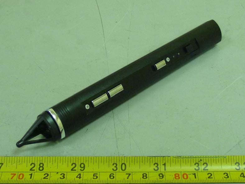
TVR-RC380P1
Oct 30, 2011Interactive pen
Equipment Class
DXX - Part 15 Low Power Communication Device Transmitter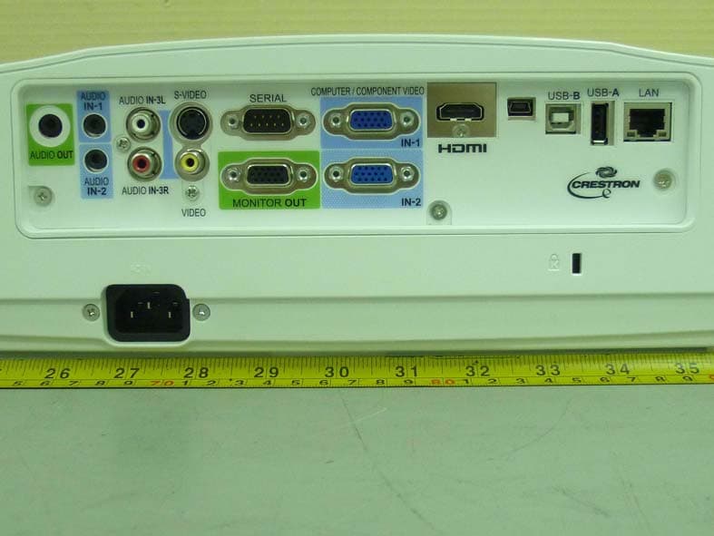
TVR-XD365UEST
Oct 30, 2011Data Projector
Equipment Class
DXX - Part 15 Low Power Communication Device Transmitter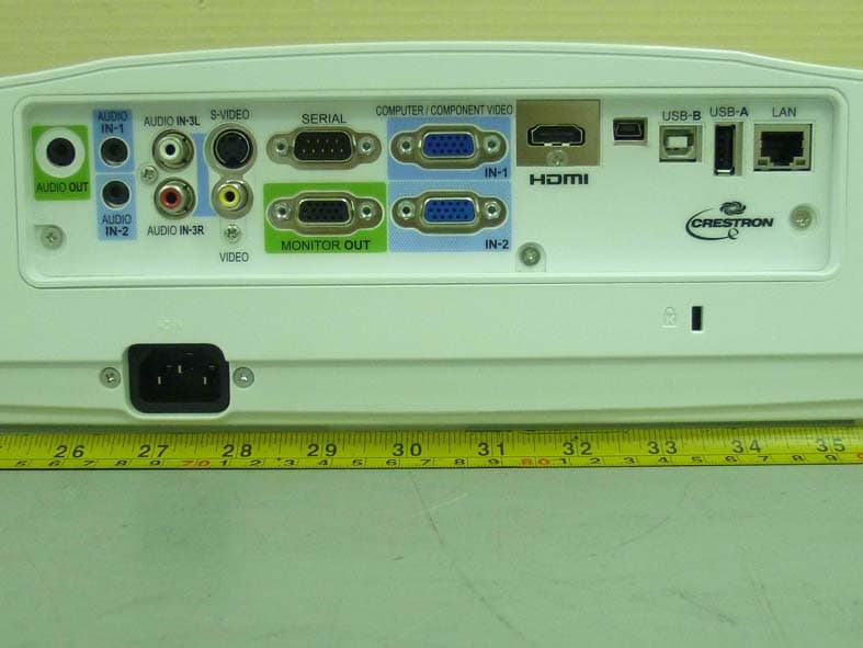
TVR-WD385UEST
Oct 27, 2011Data Projector
Equipment Class
DXX - Part 15 Low Power Communication Device Transmitter
TVRDSCS780
Dec 24, 2007Digital Still Camera
Equipment Class
JBP - Part 15 Class B Computing Device Peripheral
TVRDSCS730
Sep 09, 2007Digital Still Camera
Equipment Class
JBP - Part 15 Class B Computing Device Peripheral