TWYIPJR1000Speedway Reader
Impinj, Inc.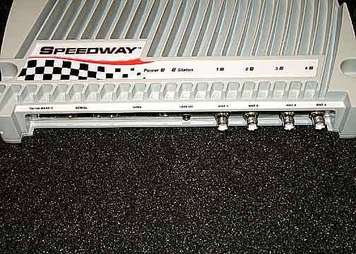
Click to zoom
Application Details
- Equipment Class
- DSS - Part 15 Spread Spectrum Transmitter
- Date of Grant
- Feb 13, 2006
- Application Purpose
- Original Equipment
- Date of Application
- Feb 12, 2006
- Equipment Note
- Speedway Reader
- Frequency Range
- 902.00000000 - 928.00000000
- Company
- Impinj, Inc.
- Country
- United States
Documents & Files
Document Text
Text extracted from the exhibit documents filed with the FCC. Open a document above to read the original.
Users Manual
REV 1.0 02-06 www.impinj.com Copyright © 2006, Impinj, Inc. Im pinj and Speedway are either registered trademarks or trademarks of Speedway Reader IPJ-R1000 for Gen 2 UHF RFID PRELIMINARY USER GUIDE Overview The EPCglobal™-certified Speedway™ IPJ-R1000 is a fixed Gen 2 UHF RFID tag reader that provides network connectivity between tag data and enterprise system software. A key element of Impinj's GrandPrix™ RFID system solution, Speedway is the first high-performance reader designed from the ground up to support the EPCglobal Gen 2 standard in its entirety. That includes the accommodation of 640 kbps tag-to- reader data rates, robust performance in dense-reader environments (without the requirement for network synchronization), the elimination of ghost reads, and more. Combined with an extensible architecture that supports seamless integration of field- upgradeable, third party application software, Speedway is the most adaptable reader solution available today. This user guide provides instructions on how to install, configure, operate, and troubleshoot the Speedway reader. It assumes the user is familiar with appropriate networking facilities, the EPCglobal™ Gen 2 specification, and general principles of RFID system management. Speedway Reader IPJ-R1000 for Gen 2 UHF RFID 2 Federal Communications Commission (FCC) Compliance This equipment has been tested and found to comply with the limits for a Class B digital device, pursuant to Part 15 of the FCC Rules. These limits are designed to provide reasonable protection against harmful interference in a commercial environment. This equipment generates, uses and can radiate radio frequency energy and, if not installed and used in accordance with the instructions, may cause harmful interference to radio communications. However, there is no guarantee that interference will not occur in a particular installation. If this equipment does cause harmful interference to radio or television reception, which can be determined by turning the equipment off and on, the user is encouraged to try to correct the interference by one or more of the following measures: • Reorient or relocate the receiving antenna • Increase the separation between the equipment and receiver • Consult the dealer or an qualified radio/TV technician for assistance Note: Changes to this product will void the user's authority to operate per FCC Part 15. Industry Canada (IC) Compliance Operation is subject to the following two conditions: (1) this device may not cause interference, and (2) this device must accept any interference, including interference that may cause undesired operation of the device. This device has been designed to operate with the antenna(s) listed in the section entitled, "Connecting the Antenna(s)," and having a maximum gain of 6 dB. Antennas not included in this list or having a gain greater than 6 dB are strictly prohibited for use with this device. The required antenna impedance is 50 ohms. To reduce potential radio interference to other users, the antenna type and its gain should be so chosen that the equivalent isotropically radiated power (e.i.r.p.) is not more than that permitted for successful communication. Note: The term “IC:” before the radio certification number only signifies that Industry of Canada technical specifications were met. Before You Begin Please read this document in its entirety before operating the Speedway reader, as serious personal injury and/or equipment damage may result from improper use. ! Speedway Reader IPJ-R1000 for Gen 2 UHF RFID 3 Unpacking the Speedway Reader Your Speedway reader has been shipped with the following: • Speedway reader unit • Power supply module (CUI, Inc., P/N DTS240259U-P11P-DB) with 24VDC output (power supply module ordered separately). Note: the use of any other power supply module may cause damage to the reader Other System and Equipment Requirements The components and accessories detailed below are required in order to ensure compliance with the Speedway reader. It is the responsibility of the user or professional installer to provide and properly use all these components and accessories: • A PC running Windows 2000 or higher or XP and - An available RS-232 serial port - An Ethernet port • Standard, grounded DB9 serial cable • Standard Ethernet cable(s) • TCP/IP network equipment, as required to connect the reader to a PC • Impinj-approved UHF RFID antenna(s), including associated RF cable with RP-TNC male connector interface • http browser that includes Java Runtime Environment (JRE) of version 1.4.2 or later. Note that Windows 2000 default is 1.3.1. The latest version of JRE can be downloaded from: http://java.com/en/download/manual.jsp Speedway Reader I/O Ports Refer to Figure 1 for the Speedway reader's major ports, connectors, and status indicators, which are clearly indicated on the unit. The Speedway reader is equipped with the following ports: • RJ-45 Ethernet jack (labeled 10/100 BASE-T) • Four female RP-TNC RF antenna connectors (ANT1 – ANT4) • Female DB-9 connector for serial communication (SERIAL) • Female DB-25 connector with user I/O capability (GPIO: RS-232 serial, four 3.3/5V logic inputs, eight 3.3V logic outputs). The LEDs indicate power (red), status (yellow), and antenna activity (red). Note that the LEDs that correspond to the connected antenna(s) only light when active (transmitting). RJ-45 Ethernet Jack RP-TNC RF Antenna Connectors DB-9 Serial Port DB-25 GPIO Port Power Input Figure 1 Impinj Speedway Reader Port Connections Speedway Reader IPJ-R1000 for Gen 2 UHF RFID 4 Mounting the Speedway Reader When securing the unit with #10 screws via the four mounting brackets, the Speedway reader may be mounted horizontally or vertically on a stable surface where it will be safe from disturbance. Keep the unit away from direct sunlight, high humidity, extreme temperatures, vibration, and sources of electromagnetic interference, as any combination of these conditions may degrade performanc…
Text truncated - open the document above for the full version.
Cover Letter(s)
Response to E06-000025-1 and E06-000025-1 IC E06-000025-1 1. A revised confidentiality letter has been uploaded. 2. A list of antennas and cable combinations has been uploaded. 3. A revised test report has been uploaded. 4. Conducted emissions was not performed on the antenna port and it is not required by the standard. 5. A description of 15.247(h) has been uploaded. E06-000025-1 IC 1. A revised application with the Canadian representative has been uploaded. 2. A revised manual has been uploaded. 3. A revised manual has been uploaded.
Cover Letter(s)
Non-Conformities FCC ID: TWYIPJR1000 (Ref # E06-00 0025-1) The items listed below represent requests for infor mation following review of this application. Furth er question may arise pending review of responses t o these items. OK # Non-Conformity or Comment Submitted Response Respondent / Date of Response X 1 It is recommended by the FCC that the letter of confidentiality refer to both 47 CFR §0.457 and §0.459. Please revise confidenti ality letter as appropriate. Revised letter provided CKC Laboratories 2/10/06 X 2 The users manual refers to a specific model num ber of antenna which is approved for use with this product. Please supply a complete list of antennas and/or cable combinations which are approved for us e with this product. TCB TO ADDRESS Need further clarification on antenna selection; user is capable of selecting antennas for use with the prod uct. TCB to review list of antennas and compare with applicable limits. List provided (only a singular antenna, just as listed in the users manual). Grant notes listed appropriately. CKC Laboratories 2/10/06 X 3 Please show data demonstrating compliance to 15 .247(a)(1)(i), time of occupancy. The compliance to this part should be c learly demonstrated without the need to decipher the provided plots. Revised test report provided CKC Laboratories 2/10/06 X 4 Since the transmitter has a removable antenna, were conducted emissions performed on the antenna port? If so, please provi de data demonstrating compliance to 15.247(d) Conducted not performed, all radiated tests. CKC Laboratories 2/10/06 X 5 Please provide a description regarding FHSS inc orporation of intelligence in accordance with 15.247(h), “The coordination of FHS S systems in any other manner for the express purpose of avoiding the simu ltaneous occupancy of individual hopping frequencies by multiple transmit ters is not permitted.“ Information provided. CKC Laboratories 2/10/06
External Photos
Side 1 Side 2
ID Label/Location Info
!"##$ %"&%' % " ( ) $ * " ' % ) * " ' ! * &"))$ + , - . / 0 , 1 2 3 , 4 2 5 . - 2 + . 6 7 + ! " # $ % & ' % ( ) ! * + , + - " . . / % ' 0 ! 1 2 3 4 5 2 & 6 ) # 6 7 7 8 ' 8 % $ # 9 & ) 8 $ # : 6 ' # ' 6 & ) * 6 $ # ( ) % 0 ; # % ; ; $ 8 ! : . / - < = , + > . ? . . % @'!7 A . / - < = , + > . ? . . % @'!7 A B 8 ! C # ' 6 & B ! & ) 8 6 & # # ) D 8 * : # % & A $ ! ; % * ) # & 6 " : C A ( 8 E ! ' ( D ! ! ) F 7 8 $ ! # & % 0 ! F : 6 # & 6 ) # ( ' % $ ! # : * % C 8 & A $ 2 , 3 2 $ ! ' # $ ! B ! $ F : % ) ! F @ G F ; % * ) # & 6 " + , + - " . . / > & H I / ? ? = ! " # $ % & ' % ( ) ! * J J J J J J ! ' # $ ! B ! $ F : % ) ! F @ G F ; % * ) # & 6 " + , + - " . . / > & H I / ? ? = J J J J J J This device complies with Part 15 of FCC Rules. Operation is subject to the following two conditions: (1) this device may not cause harmful interference, and (2) this device must accept any interference received, including interference that may cause undesired operation. FCC ID: TWYIPJR1000MADE IN USA SPEEDWAY EPC GEN2 RFID READER IC: 6324A-IPJR1000 Label no smaller than 1" x 2" Label attached to side of reader
Internal Photos
Top Bottom Inside Top Inside Bottom PCB Top PCB Bottom PCB in Case
Operational Description
Section 15.247 (h) Compliance: Each Speedway reader hops among its 50 available channels according to an independently generated pseudo-random sequence. The reader maintains no capability to coordinate RF channel occupancy among separate units.
Test Report
Page 1 of 67 Report No: FC06-010A ADDENDUM TO IMPINJ, INCORPORATED TEST REPORT FC06-010 FOR THE SPEEDWAY READER, IPJ-R1000 FCC PART 15 SUBPART B SECTIONS 15.107 & 15.109 CLASS B, SUBPART C SECTIONS 15.207, 15.209 & 15.247 AND RSS-210 COMPLIANCE DATE OF ISSUE: FEBRUARY 10, 2006 PREPARED FOR: Impinj, Incorporated 701 N. 34th Street, Suite 300 Seattle, WA 98103 PREPARED BY: Mary Ellen Clayton CKC Laboratories, Inc. 5046 Sierra Pines Drive Mariposa, CA 95338 P.O. No.: W.O. No.: 01143 83127 Date of test: January 25-26, 2006 Report No.: FC06-010A This report contains a total of 67 pages and may be reproduced in full only. Partial reproduction may only be done with the written consent of CKC Laboratories, Inc. The results in this report apply only to the items tested, as identified herein. Page 2 of 67 Report No: FC06-010A TABLE OF CONTENTS Administrative Information .............................................................................................4 FCC to Canada Transmitter Standard Correlation Matrix ...............................................5 Conditions for Compliance ..............................................................................................5 Approvals .........................................................................................................................5 Equipment Under Test (EUT) Description ......................................................................6 FCC 15.31(e) Voltage Variation......................................................................................6 FCC 15.31(m) Number Of Channels ...............................................................................6 FCC 15.33(a) Frequency Ranges Tested .........................................................................6 FCC 15.35 Analyzer Bandwidth Settings ........................................................................6 FCC 15.203 Antenna Requirements ................................................................................6 FCC 15.205 Restricted Bands..........................................................................................7 EUT Operating Frequency ...............................................................................................7 Equipment Under Test .....................................................................................................7 Peripheral Devices ...........................................................................................................7 Report of Measurements ..................................................................................................8 Table 1: FCC 15.107 Six Highest Conducted Emission Levels ..........................8 Table 2: FCC 15.109 Six Highest Radiated Emission Levels .............................9 Table 3: FCC 15.207 Six Highest Conducted Emission Levels ..........................10 Table 4: FCC 15.209 Six Highest Radiated Emission Levels: 10-30 MHz.........11 Table 5: FCC 15.209/15.247 Six Highest Radiated Emission Levels .................12 FCC 15.247(a)(1) 20dB Bandwidth.....................................................................13 FCC 15.247(a)(1) Frequency Separation .............................................................16 FCC 15.247(a)(1) Number Of Hopping Channels...............................................17 FCC 15.247(a)(1) Dwell Time Per Hop ..............................................................18 FCC 15.247(a)(1) (i) Average Time Of Occupancy ............................................20 RSS-210 Average Time Of Occupancy – 10 Seconds.........................................22 Table 6: FCC 15.247(b)(2) Fundamental Emission Levels .................................23 FCC 15.247(d) Bandedge ....................................................................................24 RSS-210 99% Bandwidth ....................................................................................26 Temperature And Humidity During Testing....................................................................29 EUT Setup........................................................................................................................29 Correction Factors............................................................................................................29 Table A: Sample Calculations .............................................................................29 Test Instrumentation and Analyzer Settings ....................................................................30 Spectrum Analyzer Detector Functions ...............................................................30 Peak..........................................................................................................30 Quasi-Peak ...............................................................................................30 Average ....................................................................................................30 EUT Testing.....................................................................................................................31 Mains Conducted Emissions................................................................................31 Antenna Conducted Emissions ............................................................................31 Radiated Emissions ..............................................................................................31 Page 3 of 67 Report No: FC06-010A Appendix A: Test Setup Photographs..............................................................................32 Photograph Showing Voltage Variations.............................................................33 Photograph Showing Mains Conducted Emissions .............................................34 Photograph Showing Mains Conducted Emissions .............................................35 Photograph Showing Radiated Emissions ...........................................................36 Photograph Showing Radiated Emissio…
Text truncated - open the document above for the full version.
Test Setup Photos
PHOTOGRAPH SHOWING VOLTAGE VARIATIONS PHOTOGRAPH SHOWING MAINS CONDUCTED EMISSIONS Mains Conducted Emissions - Front View PHOTOGRAPH SHOWING MAINS CONDUCTED EMISSIONS Mains Conducted Emissions - Side View PHOTOGRAPH SHOWING RADIATED EMISSIONS Radiated Emissions - Front View PHOTOGRAPH SHOWING RADIATED EMISSIONS Radiated Emissions - Back View PHOTOGRAPH SHOWING RADIATED EMISSIONS Radiated Emissions - Back View PHOTOGRAPH SHOWING DIRECT CONNECT POWER PHOTOGRAPH SHOWING DIRECT CONNECT SPURIOUS EMISSIONS
Contact Information
Applicant
Bill Ashley
Technical Contact
CKC Laboratories, Inc.Mary Ellen Clayton
[email protected]800-500-4362
5046 Sierra Pines Drive · Mariposa, California · United States
Test Firm
CKC Laboratories, Inc.Steve Behm
Technical Specifications
| # | Rule Parts | Frequency Range | Power Output |
|---|---|---|---|
| 1 | 15C | 902 MHz - 928 MHz | 977.20 mW |
Other Applications from Impinj, Inc.

TWYR700
Jan 06, 2020RAIN RFID Reader
Equipment Class
DSS - Part 15 Spread Spectrum Transmitter
TWYXARRAY
Jul 16, 2014xArray IPJ-REV-R680 UHF RFID reader system
Equipment Class
DSS - Part 15 Spread Spectrum Transmitter
TWYIPJR640
Jun 07, 2010RFID Integrated Reader, IPJR640
Equipment Class
DSS - Part 15 Spread Spectrum Transmitter