TWYR700RAIN RFID Reader
Impinj, Inc.
Click to zoom
Application Details
- Equipment Class
- DSS - Part 15 Spread Spectrum Transmitter
- Date of Grant
- Jan 06, 2020
- Application Purpose
- Original Equipment
- Date of Application
- Dec 18, 2019
- Equipment Note
- RAIN RFID Reader
- Frequency Range
- 902.75000000 - 927.25000000
- Company
- Impinj, Inc.
- Country
- United States
Documents & Files
Document Text
Text extracted from the exhibit documents filed with the FCC. Open a document above to read the original.
Users Manual
Impinj R700 RAIN RFID Reader Installation and Operations Guide Version 6.2.0 Copyright © 2012 - 2019 Impinj, Inc. All rights reserved http://www.impinj.com Impinj, Octane, Speedway, and Reader are either registered trademarks or trademarks of Impinj, Inc. Visit www.impinj.com/trademarks for additional information about Impinj trademarks. Impinj R700 RAIN RFID Reader Installation and Operations version 6.2.0 2 Contents PRODUCTS COVERED BY THIS GUIDE .................................................................................... 5 Federal Communications Commission (FCC) Compliance ...................................................... 5 Per FCC 15.19(a)(3) and (a)(4) ....................................................................................... 5 Per FCC 15.21 ................................................................................................................. 6 Minimum Separation Distance ...................................................................................... 6 CE Marking and European Economic Area (EEA) .................................................................... 7 Environmental Air Handling Space (EAHS) Applications ......................................................... 7 Power Requirements .............................................................................................................. 8 Before You Begin ...................................................................................................................... 8 INTRODUCTION ................................................................................................................... 9 About this Guide ..................................................................................................................... 9 Intended Audience .................................................................................................................. 9 Other Documents of Interest .................................................................................................. 9 Document Conventions ........................................................................................................ 10 Impinj Support Information .................................................................................................. 10 INTRODUCTION TO IMPINJ R700 RAIN RFID Reader ........................................................... 11 Supported Operating Environments ..................................................................................... 12 Supported Communication Protocol ................................................................................... 12 Antenna Requirements ........................................................................................................ 12 INSTALLING AND CONNECTING IMPINJ R700 RAIN RFID READER ........................................ 13 Impinj R700 RAIN RFID Reader Ports and LEDs .................................................................... 13 Impinj R700 RAIN RFID Reader LED Blink Patterns ...................................................... 13 LED Behavior in Scenarios for Startup, Upgrade, Detection, Inventory, and LLRP ...... 14 Installing and Connecting the Reader .................................................................................. 15 Detailed Installation Procedures ........................................................................................... 16 Step 1: Position the Impinj R700 RAIN RFID Reader and (optionally) Mount the Reader ............................................................................................................. 16 To Mount the Impinj R700 RAIN RFID Reader ............................................................. 16 Step 2: Connect the Antenna(s) to the Impinj R700 RAIN RFID Reader ...................... 17 Impinj R700 RAIN RFID Reader Installation and Operations version 6.2.0 3 To Connect the Antenna(s) to the Reader ................................................................... 17 Step 3: Power the Reader ............................................................................................ 17 Step 4: Connect the Impinj R700 RAIN RFID Reader to the Network ......................... 18 To Connect the Impinj R700 RAIN RFID Reader to the Ethernet Network .................. 20 To Troubleshoot Ethernet Network Connections ........................................................ 20 To Connect the Impinj R700 RAIN RFID Reader to Your PC Over a Serial Connection 20 CONFIGURING AND MONITORING IMPINJ R700 RAIN RFID READER ................................... 22 Configuring Impinj R700 RAIN RFID Reader .......................................................................... 22 Device Configuration ................................................................................................... 22 Using RShell to Configure Network Settings for Impinj R700 RAIN RFID Reader ........ 22 To Configure the Reader’s Network Settings .............................................................. 23 RF Configuration ........................................................................................................... 23 Download ItemTest ................................................................................................................ 24 Install and Launch ItemTest................................................................................................... 24 Connect and Configure the Reader ....................................................................................... 25 To Connect and Configure Your Reader ...................................................................... 26 To Configure the Reader for Inventory ........................................................................ 28 Monitoring Impinj R700 RAIN RFID Reader .......................................................................... 29 Viewing Network Parameters and Statistics ...............................................…
Text truncated - open the document above for the full version.
Cover Letter(s)
12/19/2019 Federal Communications Commission 7435 Oakland Mills Road Columbia, MD 21046 Subject: Request for Permanent Confidentiality To whom it may concern: In accordance with 47CFR Section 0.457 and Section 0.459 pertaining to confidential material, we hereby request to hold permanently confidential all information contained within the below identified exhibits/document categories submitted pursuant to radio equipment certification requirements for FCC ID: TWYR700 1. Block Diagram 2. Operational Description/Theory of Operations 3. Schematics 4. Parts List / Bill of Materials The above material contains trade secrets and proprietary information as specified by 47CFR 0.457(d) and technical data, which would customarily be guarded from competitors. The public disclosure of this information might be harmful to our company and provide unjustified benefits to our competitors. Sincerely, Michelle Branum, CKC CS, on behalf of Bill Ashley VP of Hardware Engineering Impinj, Inc.
Cover Letter(s)
19 December 2019 To Whom It May Concern: Impinj requests that “Professional Installation” is listed on the FCC certification. In justifying this request, we evaluated our Impinj R700 RAIN RFID reader product against FCC KDB 353028 D01 section II A 2 c criteria as follows: c) Professional installation i) Professional installation must be justified in the filing, and grant condition must state “This device must be professionally installed.” RESPONSE / JUSTIFICATION – Agreed, Professional installation required will be listed on certification and stated in the operation and installation manual ii) Professional installation does not permit use of any antenna with the transmitter; the permitted types of antenna must be specified. RESPONSE / JUSTIFICATION – Approved and tested antennas are listed in the operation and installation manual iii) The applicant should address the following items when justifying professional installation. (1) To qualify for professional installation, the applicant must explain why the hardware is not readily available to average consumer. RESPONSE / JUSTIFICATION – Impinj does not market to sell this product to consumers and does not sell thru consumer channels (2) Marketing—Device cannot be sold via retail to the general public or by mail order; it must be sold to authorized dealers or installers only. RESPONSE / JUSTIFICATION – We only offer this product to licensed and trained Solution Providers that sign an agreement with Impinj (3) Filing must show that intended use is not for consumers and general public; rather device is generally for industrial/commercial use. RESPONSE / JUSTIFICATION – Impinj’s licensed Solution Providers develop specific solutions for industrial or retail customers to use RFID based systems in their factories or other facilities (4) Explain what is unique, sophisticated, complex, or specialized about the equipment that REQUIRES it to be installed by a professional installer? RESPONSE / JUSTIFICATION – Impinj’s R700 RAIN RFID Reader does not have a default mode of operation (out of the box). The Impinj R700 RFID reader is one component of larger industrial system. To perform a useful function, requires that one of Impinj’s Solution Providers develop a system solution, which typically includes custom software, RF system design, validation testing and installation. Impinj’s Solution Providers have expertise in RF, systems, and software engineering that enable to develop overall solutions that they market to end industrial and retail customers. iv) Other professional installation requirements. (1) Installation must be controlled. RESPONSE / JUSTIFICATION – Impinj’s licensed Solution Providers install and validate the RFID systems via design plans, installation procedures, and test verification plans that they develop (2) Installed by licensed professionals (e.g., device sold to dealer who hire installers). RESPONSE / JUSTIFICATION – Impinj’s licensed Solution Providers sign licensing / partner agreement with Impinj (3) Installation requires special training (e.g., special programming, access to keypad, field strength measurements made). RESPONSE / JUSTIFICATION – Impinj’s licensed Solution Providers are required to obtain on-site training classes offered by Impinj personal. The training includes determining cable losses, safe operating distances, and other factors to correctly configure the TX power level to operate within FCC rules. Sincerely, Michelle Branum, CKC CS, on behalf of Bill Ashley VP of Hardware Engineering Impinj, Inc.
ID Label/Location Info
Material: Stock label color: Black Text color: White Gloss: Level between 8 and 20 Board ID: U = Serialized digits for Board ID Serial Number: V = Serialized digits for Serial Number Ethernet MAC Address: W = Serialized digits for MAC Address Model Number: X = Region Identifier - 1 = FCC; 2 = EU; 3 = Global; 4 = Japan; 5 = Australia Y = Port Identifier --> 1 = 1-port; 2 = 2-port; 4 = 4-port Z = Feature Identifier --> 0 = no added features; 1 = WiFi QR Code: Should not be any larger than 12mm x 12mm. Smaller is preferred. 1. The following information should be encoded into QR code on the HLA and FG QR code label: HLA number, PCBA number, Board ID, Ethernet Mac Address, Model Number and Serial Number. Notes IMPINJ R700 RAIN RFID READER ™ This device complies with Part 15 of FCC rules. Operation is subject to conditions: (1) this device may not cause harmful interference, and (2) this device must accept any interference received, including interference that may cause undesired operation. FCC ID: TWYR700 IC: 6324A-R700 Assembled in Malaysia RoHS 2015/863/EU Compliant ITE E347099 75mm 25mm R=1.5mm FG: 103100-01A PCBA: 102900-01B ETH MAC: 00:16:25:WW:WW:WW IMPINJ R700 RAIN RFID READER ™ This device complies with Part 15 of FCC rules. Operation is subject to conditions: (1) this device may not cause harmful interference, and (2) this device must accept any interference received, including interference that may cause undesired operation. FCC ID: TWYR700 IC: 6324A-R700 Assembled in Malaysia RoHS 2015/863/EU Compliant ITE E347099 75mm 25mm R=1.5mm HLA: 103000-01A PCBA: 102900-01B ETH MAC: 00:16:25:WW:WW:WW IPJ-R700-141 30.0mm 4.76mm R=1mm Material: Matte lamination Stock label color: Black Gloss: Level between 8 and 20 Text color: White Notes 15 12 13 14 5 5 5 5 1.1±0.5 1.1±0.5 15.9±0.5 16 8±0.5 TOP SIDE BOTTOM SIDE LABEL UPRIGHT ORIENTATION THE INFORMATION CONTAINED IN THIS DRAWING IS THE SOLE PROPERTY OF IMPINJ, INC. ANY REPRODUCTION IN PART OR AS A WHOLE WITHOUT THE WRITTEN PERMISSION OF IMPINJ, INC. IS PROHIBITED. PROPRIETARY AND CONFIDENTIAL SIZE B DWG. NO. REV WEIGHT: n/aSCALE: 1:2 C 089 / C SHEET 4 OF 4 102426-01 400 Fairview Ave N, Suite 1200 Seattle, WA 98109 206-517-5300 WWW.IMPINJ.COM LABEL - MAC ADDRESS - R700 LABEL - SERIAL NUMBER - R700 LABEL - PRODUCT ID - R700 LABEL - CERTIFICATION / QR BARCODE - R700
RF Exposure Info
RADIO FREQUENCY EXPOSURE REPORT FOR THE Device: Impinj R700 RAIN RFID Reader Model: IPJ-R700 Report No.: 103052-9 Date of issue: November 7, 2019 PREPARED FOR: Impinj Inc. 400 Fairview Ave N, Suite 1200 Seattle WA 98109 PREPARED BY: Matt Harrison CKC Laboratories, Inc. 5046 Sierra Pines Drive Mariposa, CA 95338 The test data contained in this report documents the observed testing parameters pertaining to and are relevant for only the sample equipment tested in the agreed upon operational mode(s) and configuration(s) as identified herein. Compliance assessment remains the client’s responsibility. This report may not be used to claim product endorsement by A2LA or any government agencies. This test report has been authorized for release under quality control from CKC Laboratories, Inc. Steve Behm Director of Quality Assurance & Engineering Services CKC Laboratories, Inc. Page 2 of 10 Report No: 103052-9 Purpose: To demonstrate compliance with United States, Canada, Australia and/or European Union RF Exposure requirements for Portable equipment (devices used ≤20cm from the body) with power output below exemption levels or Mobile equipment (devices used >20cm from the body) where Maximum Permissible Exposure (MPE) Calculations apply. Device and Antenna Operating Configuration: Device operating at maximum output power with continuous transmission of modulated data. Test Procedure: This equipment is evaluated in accordance with the guidelines set forth in KDB 447498 & ANSI C95.1 for the US, Health Canada Safety Code 6 & RSS 102 for Canada, ARPANSA RPS3 for AU and EN 62479 or EN 62311 for EU. Other Considerations: Report considers stand-alone configurations only. RF Exposure limits are calculated at the mid-point of each operating band. Referenced Test Reports: The following test reports were referenced in conjunction with this assessment: 103052-2 103052-3 Page 3 of 10 Report No: 103052-9 RF Exposure Power Density Assessment (Single Transmitter, Stand Alone) MPE Calculation: 푃표푤푒푟 퐷푒푛푠푖푡푦 ( 푆 ) = 퐸퐼푅푃 4휋 푑 2 Given: EIRP in mW or W and d in cm or m US MPE Assessment Power Reported is: ☒ Peak ☐ Average Limit Used is: ☒ General Population ☐ Occupational Exposure Operating Band MHz Power dBm Ant Type/Gain dBi EIRP dBm Distance cm MPE mW/cm 2 Limit mW/cm 2 Comments 902-928 29.6 External / -20dBi 9.6 25 0.001 0.61 Pass 902-928 29.6 External / 5.7dBi* 35.3 25 0.43 0.61 Pass 902-928 29.6 External / 5.5dBiC 35.1 25 0.412 0.61 Pass 902-928 29.6 External / 2dBi 31.6 25 0.184 0.61 Pass 902-928 29.6 External / -20dBi 9.6 25 0.001 0.61 Pass 902-928 29.6 External / 6dBi 35.6 25 0.46 0.61 Pass ** The manufacturer declares maximum linear gain is 5.7dBi based on the assumed relationship between circularly and linearly polarized gains with uncertainty IC MPE Assessment Power Reported is: ☒ Peak ☐ Average Limit Used is: ☒ General Population ☐ Occupational Exposure Operating Band MHz Power dBm Ant Type/Gain dBi EIRP dBm Distance m MPE W/m 2 Limit W/m 2 Comments 902-928 29.6 External / -20dBi 9.6 0.35 0.01 2.77 Pass 902-928 29.6 External / 5.7dBi* 35.3 0.35 2.2 2.77 Pass 902-928 29.6 External / 5.5dBiC 35.1 0.35 2.1 2.77 Pass 902-928 29.6 External / 2dBi 31.6 0.35 0.94 2.77 Pass 902-928 29.6 External / -20dBi 9.6 0.35 0.01 2.77 Pass 902-928 29.6 External / 6dBi 35.6 0.35 2.36 2.77 Pass ** The manufacturer declares maximum linear gain is 5.7dBi based on the assumed relationship between circularly and linearly polarized gains with uncertainty Page 4 of 10 Report No: 103052-9 Summary: Exemptions: Equipment demonstrating compliance by portable RF exposure exemption have been evaluated, without further testing, for use under either portable or mobile RF exposure configurations. Additional configurations including collocation or simultaneous transmission with other transmitters (including necessary separation distances) are subject to further assessment. Certain exemption criteria may define specific separation distances. It is assumed that the manufacturer shall design the equipment such that these minimum separation distance is met. MPE Calculation Results: Equipment demonstrating compliance with MPE calculations have been evaluated, without further testing, for use under mobile RF exposure configurations as identified herein. Additional configurations including collocation or simultaneous transmission with other transmitters (including necessary separation distances) are subject to further assessment. It is assumed that the manufacturer shall design the equipment such that the minimum separation distance of 20cm (or greater, as listed above) is met or that the manufacturer provides a protection guide (e.g. installation instructions) to the end user such that the antenna(s) may be installed in accordance with the manufacturer’s instructions in such a manor to maintain the minimum separation distance. General Comments: The absorption and distribution of Electromagnetic energy in the body is a very complex phenomena that depends on the mass, shape and physiological condition of the body; the orientation of the body with respect to the fields; and, the electrical properties of the body and the environment. Variables that may play a substantial role in possible biological effects are those that characterize the environment (including but not limited to: ambient temperature, air velocity, relative humidity and body insulation); and those that characterize the individual (including but not limited to: age, gender, activity level and existing debilitation or disease). Because innumerable factors may interact to determine specific biological effects of exposure to electromagnetic fields, any protection guide should consider both intended and unintended operational environments and provide guidance for installation and use of the product such that proper separation distances can be maintained. (ANSI C95.1) Page 5 of 10 Report No: 103052-9 APPENDIX A - RF Exposure Limits United States Compliance Requirements (1.1310): RF Exposur…
Text truncated - open the document above for the full version.
Test Report
This report contains a total of 260 pages and may be reproduced in full only. Partial reproduction may only be done with the written consent of CKC Laboratories, Inc. Impinj Inc. REVISED TEST REPORT TO 103052-2 Impinj R700 RAIN RFID Reader Model: IPJ-R700 Tested to The Following Standards: FCC Part 15 Subpart C Section(s) 15.207 & 15.247 (FHSS 902-928 MHz) Report No.: 103052-2A Date of issue: December 20, 2019 This test report bears the accreditation symbol indicating that the testing performed herein meets the test and reporting requirements of ISO/IEC 17025 under the applicable scope of testing for CKC Laboratories, Inc. We strive to create long-term, trust based relationships by providing sound, adaptive, customer first testing services. We embrace each of our customers’ unique EMC challenges, not as an interruption to set processes, but rather as the reason we are in business. Test Certificate # 803.01 Page 2 of 260 Report No.: 103052-2A TABLE OF CONTENTS Administrative Information .......................................................................................................................... 3 Test Report Information ............................................................................................................................................ 3 Revision History ......................................................................................................................................................... 3 Report Authorization ................................................................................................................................................. 3 Test Facility Information ............................................................................................................................................ 4 Software Versions ...................................................................................................................................................... 4 Site Registration & Accreditation Information .......................................................................................................... 4 Summary of Results ................................................................................................................................................... 5 Modifications During Testing ..................................................................................................................................... 5 Conditions During Testing.......................................................................................................................................... 5 Equipment Under Test ............................................................................................................................................... 6 General Product Information..................................................................................................................................... 9 FCC Part 15 Subpart C ................................................................................................................................. 10 15.247(a) Transmitter Characteristics ..................................................................................................................... 10 15.247(a)(1) 20 dB Bandwidth ............................................................................................................................. 11 15.247(a)(1) Carrier Separation ........................................................................................................................... 13 15.247(a)(1)(i) Number of Hopping Channels ..................................................................................................... 14 15.247(a)(1)(i) Time of Occupancy ...................................................................................................................... 15 15.247(b)(2) Output Power ..................................................................................................................................... 19 15.247(d) RF Conducted Emissions & Band Edge .................................................................................................... 30 15.247(d) Radiated Emissions & Band Edge ............................................................................................................ 62 15.207 AC Conducted Emissions ............................................................................................................................ 250 Supplemental Information ........................................................................................................................ 259 Measurement Uncertainty .................................................................................................................................... 259 Emissions Test Details ............................................................................................................................................ 259 Page 3 of 260 Report No.: 103052-2A ADMINISTRATIVE INFORMATION Test Report Information REPORT PREPARED FOR: REPORT PREPARED BY: Impinj Inc. 400 Fairview Ave N, Suite 1200 Seattle WA 98109 Darcy Thompson CKC Laboratories, Inc. 5046 Sierra Pines Drive Mariposa, CA 95338 Representative: Greg Robinson Project Number: 103052 Customer Reference Number: 702429 DATE OF EQUIPMENT RECEIPT: September 19, 2019 DATE(S) OF TESTING: September 19-30, 2019 Revision History Original: Testing of the Impinj R700 RAIN RFID Reader, Model: IPJ-R700 to FCC Part 15 Subpart C Section(s) 15.207 & 15.247 (FHSS 902-928 MHz). Revision A: Corrected Firmware power setting and added statement to the test setup on pages 27, 39, 42, 45, 57 and 59. Report Authorization The test data contained in this report documents the observed testing parameters pertaining to and are relevant for only the equipment provided by the client, tested in the agreed upon operational mode(s) and configuration(s) as identified herein. Compliance…
Text truncated - open the document above for the full version.
Test Report
Page 154 of 260 Report No.: 103052-2A Page 155 of 260 Report No.: 103052-2A Page 156 of 260 Report No.: 103052-2A Page 157 of 260 Report No.: 103052-2A Configuration 4 Page 158 of 260 Report No.: 103052-2A Page 159 of 260 Report No.: 103052-2A Page 160 of 260 Report No.: 103052-2A Page 161 of 260 Report No.: 103052-2A Page 162 of 260 Report No.: 103052-2A Page 163 of 260 Report No.: 103052-2A Configuration 5 Page 164 of 260 Report No.: 103052-2A Page 165 of 260 Report No.: 103052-2A Page 166 of 260 Report No.: 103052-2A Page 167 of 260 Report No.: 103052-2A Page 168 of 260 Report No.: 103052-2A Page 169 of 260 Report No.: 103052-2A Configuration 6 Page 170 of 260 Report No.: 103052-2A Page 171 of 260 Report No.: 103052-2A Page 172 of 260 Report No.: 103052-2A Page 173 of 260 Report No.: 103052-2A Page 174 of 260 Report No.: 103052-2A Page 175 of 260 Report No.: 103052-2A Configuration 7 Page 176 of 260 Report No.: 103052-2A Page 177 of 260 Report No.: 103052-2A Page 178 of 260 Report No.: 103052-2A Page 179 of 260 Report No.: 103052-2A Page 180 of 260 Report No.: 103052-2A Page 181 of 260 Report No.: 103052-2A Configuration 8 Port 1 Page 182 of 260 Report No.: 103052-2A Page 183 of 260 Report No.: 103052-2A Page 184 of 260 Report No.: 103052-2A Page 185 of 260 Report No.: 103052-2A Page 186 of 260 Report No.: 103052-2A Page 187 of 260 Report No.: 103052-2A Configuration 8 Port 2 Page 188 of 260 Report No.: 103052-2A Page 189 of 260 Report No.: 103052-2A Page 190 of 260 Report No.: 103052-2A Page 191 of 260 Report No.: 103052-2A Page 192 of 260 Report No.: 103052-2A Page 193 of 260 Report No.: 103052-2A Test Setup / Conditions / Data Test Location: CKC Laboratories Inc. • 22116 23rd Dr SE • Bothell, WA 98021 • 800-500-4362 Customer: Impinj, Inc. Specification: 15.247(d) / 15.209 Radiated Spurious Emissions Work Order #: 103052 Date: 9/20/2019 Test Type: Maximized Emissions Time: 13:29:28 Tested By: Matthew Harrison Sequence#: 39 Software: EMITest 5.03.12 Equipment Tested: Device Manufacturer Model # S/N Configuration 2 Support Equipment: Device Manufacturer Model # S/N Configuration 2 Test Conditions / Notes: Temperature: 22° C Humidity: 45% Pressure: 101.3 kPa Frequency Range: 30-1000MHz Frequency tested: 902.75, 927.25 Firmware power setting; 30dBm Protocol /MCS/Modulation: Continuously modulated Antenna type: Mini-Guardrail Antenna Antenna Gain: -20dBi antenna in X, Y & Z axis investigated Duty Cycle: 100% Test Method: ANSI 63.10 (2013) Setup: The EUT is set on a foam test table. The antenna is connected to antenna port 1 via a 5-meter RG058 cable 3x USB Cables and 1 GPIO Cable connected A shielded Cat5e is run from the EUT to a POE injector which is connected to a Wireless Router which is connected to the support laptop all located outside the chamber. Page 194 of 260 Report No.: 103052-2A Test Equipment: ID Asset # Description Model Calibration Date Cal Due Date T1 AN03628 Biconilog Antenna 3142E 6/11/2019 6/11/2021 T2 ANP06123 Attenuator 18N-6 4/5/2019 4/5/2021 T3 ANP05305 Cable ETSI-50T 9/6/2019 9/6/2021 T4 ANP05360 Cable RG214 1/31/2018 1/31/2020 T5 ANP06540 Cable Heliax 8/23/2019 8/23/2021 AN02673 Spectrum Analyzer E4446A 2/22/2019 2/22/2021 Measurement Data: Reading listed by margin. Test Distance: 3 Meters # Freq Rdng T1 T5 T2 T3 T4 Dist Corr Spec Margin Polar MHz dBμV dB dB dB dB Table dBμV/m dBμV/m dB Ant 1 902.751M 71.3 +23.8 +0.3 +5.8 +1.4 +2.0 +0.0 104.6 106.0 -1.4 Vert 2 927.247M 69.1 +24.2 +0.4 +5.8 +1.5 +2.0 +0.0 103.0 106.0 -3.0 Vert 3 614.000M 9.3 +21.2 +0.3 +5.8 +1.2 +1.5 +0.0 39.3 46.0 -6.7 Vert QP ^ 614.000M 13.4 +21.2 +0.3 +5.8 +1.2 +1.5 +0.0 43.4 46.0 -2.6 Vert 5 960.000M 9.3 +24.6 +0.4 +5.8 +1.5 +2.1 +0.0 43.7 54.0 -10.3 Vert QP ^ 960.000M 12.5 +24.6 +0.4 +5.8 +1.5 +2.1 +0.0 46.9 54.0 -7.1 Vert 7 902.000M 16.6 +23.8 +0.3 +5.8 +1.4 +2.0 +0.0 49.9 86.0 -36.1 Vert 8 928.000M 15.5 +24.2 +0.4 +5.8 +1.5 +2.0 +0.0 49.4 86.0 -36.6 Vert Page 195 of 260 Report No.: 103052-2A Test Location: CKC Laboratories Inc. • 22116 23rd Dr SE • Bothell, WA 98021 • 800-500-4362 Customer: Impinj, Inc. Specification: 15.247(d) / 15.209 Radiated Spurious Emissions Work Order #: 103052 Date: 9/23/2019 Test Type: Maximized Emissions Time: 08:16:10 Tested By: Matthew Harrison Sequence#: 40 Software: EMITest 5.03.12 Equipment Tested: Device Manufacturer Model # S/N Configuration 2 Support Equipment: Device Manufacturer Model # S/N Configuration 2 Test Conditions / Notes: Temperature: 22° C Humidity: 45% Pressure: 101.3 kPa Frequency Range: 30-1000MHz Frequency tested: 902.75, 927.25 Hopping Firmware power setting; 30dBm Protocol /MCS/Modulation: Continuously modulated Antenna type: Mini-Guardrail Antenna Antenna Gain: -20dBi antenna in X, Y & Z axis investigated Duty Cycle: 100% Test Method: ANSI 63.10 (2013) Setup: The EUT is set on a foam test table. The antenna is connected to antenna port 1 via a 5-meter RG058 cable 3x USB Cables and 1 GPIO Cable connected A shielded Cat5e is run from the EUT to a POE injector which is connected to a Wireless Router which is connected to the support laptop all located outside the chamber. Page 196 o…
Text truncated - open the document above for the full version.
Contact Information
Applicant
Bill Ashley
Test Firm
CKC Laboratories, Inc.Steve Behm
Technical Specifications
| # | Rule Parts | Frequency Range | Power Output |
|---|---|---|---|
| 1 | 15C | 902.75 MHz - 927.25 MHz | 912.00 mW |
Other Applications from Impinj, Inc.
TWYXARRAY
Jul 16, 2014xArray IPJ-REV-R680 UHF RFID reader system
Equipment Class
DSS - Part 15 Spread Spectrum Transmitter
TWYIPJR640
Jun 07, 2010RFID Integrated Reader, IPJR640
Equipment Class
DSS - Part 15 Spread Spectrum Transmitter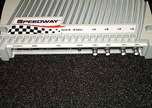
TWYIPJR1000
Feb 13, 2006Speedway Reader
Equipment Class
DSS - Part 15 Spread Spectrum Transmitter