TX2-RTL8821AU802.11a/b/g/n/ac RTL8821AU Combo module
Realtek Semiconductor Corp.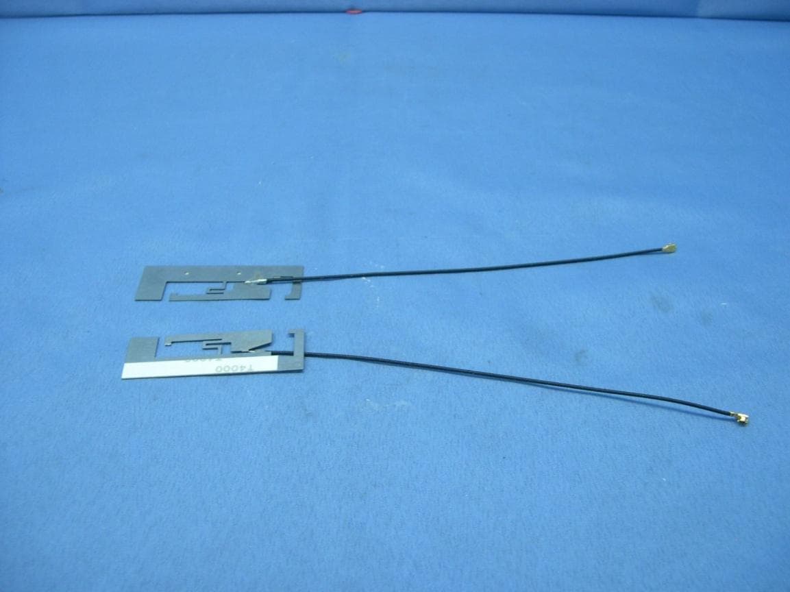
Click to zoom
Application Details
- Equipment Class
- NII - Unlicensed National Information Infrastructure TX
- Date of Grant
- Mar 05, 2014
- Application Purpose
- Original Equipment
- Date of Application
- Mar 05, 2014
- Equipment Note
- 802.11a/b/g/n/ac RTL8821AU Combo module
- Frequency Range
- 5660.00000000 - 5700.00000000
- Company
- Realtek Semiconductor Corp.
- Country
- Taiwan
Documents & Files
Document Text
Text extracted from the exhibit documents filed with the FCC. Open a document above to read the original.
Users Manual
Combo module User’s Manual Rev.0.1 20 December 2013 Realtek Semiconductor Corp. No. 2, Innovation Road II, Hsinchu Science Park, Hsinchu 300, Taiwan Tel.: +886-3-578-0211. Fax: +886-3-577-6047 www.realtek.com.tw RTL8821AU RTL8821AU Combo module User Manual ii COPYRIGHT ©2012 Realtek Semiconductor Corp. All rights reserved. No part of this document may be reproduced, transmitted, transcribed, stored in a retrieval system, or translated into any language in any form or by any means without the written permission of Realtek Semiconductor Corp. DISCLAIMER Realtek provides this document ‘as is’, without warranty of any kind. Realtek may make improvements and/or changes in this document or in the product described in this document at any time. This document could include technical inaccuracies or typographical errors. TRADEMARKS Realtek is a trademark of Realtek Semiconductor Corporation. Other names mentioned in this document are trademarks/registered trademarks of their respective owners. USING THIS DOCUMENT This document is intended for the software engineer’s reference and provides detailed programming information. Though every effort has been made to ensure that this document is current and accurate, more information may have become available subsequent to the production of this guide. REVISION HISTORY Revision Release Date Summary 0.1 2013/12/20 Preliminary release. RTL8821AU Combo module User Manual iii Table of Contents 1. GENERAL DESCRIPTION ......................................................................................................................................... 1 2. PRODUCT SPECIFICATIONS ................................................................................................................................... 3 2.1. ENVIRONMENTAL ..................................................................................................................................................... 3 2.1.1. Operating ........................................................................................................................................................ 3 2.1.2. Storage ............................................................................................................................................................ 3 2.2. FUNCTIONAL SPECIFICATIONS ................................................................................................................................... 3 2.3. WARNING ................................................................................................................................................................ 5 3.5.1 Federal Communication Commission Interference Statement ................................................................................. 5 3.5.2 Industry Canada Statement ................................................................................................................................... 6 3.5.3 NCC 警語 ........................................................................................................................................................... 10 List of Tables TABLE 2. FUNCTIONAL SPECIFICATIONS .................................................................................................................................. 3 RTL8821AU Combo module User Manual 1 1. General Description The Realtek RTL8821AU is a highly integrated single-chip 802.11a/b/g/n/ac 1T1R USB2.0 WLAN controller. It combines a WLAN MAC, a 1T1R capable WLAN baseband, BT Protocol Stack (LM, LL, and LE), BT Baseband, modem, and WLAN/BT RF in a single chip. The RTL8821AU provides a complete solution for a high throughput performance integrated wireless LAN and Bluetooth device. The RTL8821AU WLAN baseband implements Orthogonal Frequency Division Multiplexing (OFDM) with 1 transmit and 1 receive path and is compatible with the 802.11ac specification. Features include one spatial stream transmission, short guard interval (GI) of 400ns, spatial spreading, and transmission over 20MHz , 40MHz and 80MHz channel bandwidth. For legacy compatibility, Direct Sequence Spread Spectrum (DSSS), Complementary Code Keying (CCK) and OFDM baseband processing are included to support all 802.11b and 802.11g data rates. Differential phase shift keying modulation schemes, DBPSK and DQPSK with data scrambling capability, are available, and CCK provides support for legacy data rates, with long or short preamble. The high-speed FFT/IFFT paths, combined with BPSK, QPSK, 16QAM, 64QAM and 256-QAM modulation of the individual subcarriers and rate compatible punctured convolutional coding with coding rate of 1/2, 2/3, 3/4, and 5/6, provide up to 433.3Mbps for 802.11ac OFDM. A RTL8821AU built-in enhanced signal detector, adaptive frequency domain equalizer, and a soft-decision Viterbi decoder help to alleviate multi-path effects and mutual interference in the reception of multiple streams. Robust interference detection and suppression are provided to protect against Bluetooth, cordless phone, and microwave oven interference. Efficient IQ-imbalance, DC offset, phase noise, frequency offset, and timing offset compensations are provided for the radio frequency front-end. Selectable digital transmit and receive FIR filters are provided to meet transmit spectrum mask requirements and to reject adjacent channel interference, respectively. The RTL8821AU WLAN Controller supports fast receiver Automatic Gain Control (AGC) with synchronous and asynchronous control loops among antennas, antenna diversity functions, and adaptive transmit power control function to obtain better performance in the analog portions of the transceiver. The RTL8821AU WLAN MAC supports 802.11e for multimedia applications, 802.11i for security, and 802.11n/802.11ac Draft 2.0 for enhanced MAC protocol efficiency. Using packet aggregation techniques such as A-MPDU with BA and A-MSDU, protocol efficiency is significantly improved. Power saving mechanisms such as Legacy Power Save,…
Text truncated - open the document above for the full version.
Attestation Statements
Realtek Semiconductor Corp. No. 2, Innovation Road II, Hsinchu Science Park, Hsinchu 300, Taiwan Declaration Letter Date: February 14, 2014 We, Realtek Semiconductor Corp. declare that the device does not support channel 12 ~ 13 in 2.4GHz band and any non-US channels in all the operational mode(s) for the following product. FCC ID: TX2-RTL8821AU If you should have any question(s) regarding this declaration, please don’t hesitate to contact us. Thank you! ----------------------------------- Dana Liaw Realtek Semiconductor Corp. Tel: +886-3-578-0211*3164 Fax: +886-3-577-6598 E-Mail: [email protected]
Attestation Statements
Realtek Semiconductor Corp. No. 2, Innovation Road II, Hsinchu Science Park, Hsinchu 300, Taiwan DFS client device channel plan and software operational declaration Date: 2014-01-16 We, Realtek Semiconductor Corp., declare that the device, FCC ID: TX2-RTL8821AU Model Name: RTL8821AU, does not have “Ad Hoc on non-US frequencies” and/or “on DFS frequencies. Also, the client software and associated drivers will not initiate any transmission on DFS frequencies without initiation by a master. This includes restriction on transmissions for beacons and support for ad-hoc peer-to-peer modes. Below is the channel / frequency plan for the device Also, on DFS channels, the WLAN driver in the device operates under the control of an AP at all times, except when in ad-hoc mode, on US non-DFS channels. The device passively scans DFS frequencies until a master device is detected. The control of this functionality is not accessible to anyone under any conditions. Furthermore, the firmware is protected by special signature and CRC checksum. Signature and CRC checksum will be calculated and verified before firmware upgrade. Unauthorized modification to firmware will lead the failure of verification thus firmware upgrade is not allowed. Sincerely yours, ------------------------------------------------------- Dana Liaw Realtek Semiconductor Corp. Tel: +886-3-578-0211*3164 Fax: +886-3-577-6598 E-Mail: [email protected] CH 1 2 3 4 5 6 7 8 9 10 11 Frequency (MHz) 2412 2417 2422 2427 2432 2437 2442 2447 2452 2457 2462 Scan Type Active Active Active Active Active Active Active Active Active Active Active CH 36 38 40 42 44 48 52 54 56 58 60 Frequency (MHz) 5180 5190 5200 5210 5220 5240 5260 5270 5280 5290 5300 Scan Type Active Active Active Active Active Active Passive Passive Passive Passive Passive CH 62 64 Frequency (MHz) 5310 5320 Scan Type Passive Passive CH 100 102 104 106 108 110 112 116 132 134 136 Frequency (MHz) 5500 5510 5520 5530 5540 5550 5560 5580 5660 5670 5680 Scan Type Passive Passive Passive Passive Passive Passive Passive Passive Passive Passive Passive CH 140 Frequency (MHz) 5700 Scan Type Passive CH 149 151 153 155 157 159 161 165 Frequency (MHz) 5745 5755 5765 5775 5785 5795 5805 5825 Scan Type Active Active Active Active Active Active Active Active
Cover Letter(s)
Realtek Semiconductor Corp. No. 2, Innovation Road II, Hsinchu Science Park, Hsinchu 300, Taiwan Federal Communications Commission 7435 Oakland Mills Road Columbia MD 21046 Date: 2014/01/16 Subject: Request for Confidentiality FCC ID: TX2-RTL8821AU To Whom It May Concern: Pursuant to the provisions of Sections 0.457 and 0.459 of the Commission’s rules (47 CFR §§ 0.457, 0.459), we are requesting the Commission to withhold the following attachments as confidential document from public disclosure indefinitely. Schematic Diagram Block Diagram Theory of Operation Above mentioned document contains detailed system and equipment description are considered as proprietary information in operation of the equipment. The public disclosure of above documents might be harmful to our company and would give competitor an unfair advantage in the market. In additional to above mentioned documents, pursuant to Public Notice DA 04-1705 of the Commission’s policy, in order to comply with the marketing regulations in 47 CFR §2.803 and the importation rules in 47 CFR §2.1204, while ensuring that business sensitive information remains confidential until the actual marketing of newly authorized devices. We are requesting the commission to grant short-term confidentiality request on the following attachments until 2014/04/30. External Photos Internal Photos Test setup Photos User Manual It is our understanding that all measurement test reports, FCC ID label format and correspondent during certification review process cannot be granted as confidential documents and those information will be available for public review once the grant of equipment authorization is issued. Best Regards Sincerely yours, ------------------------------------------------------- Dana Liaw Realtek Semiconductor Corp. Tel: +886-3-578-0211*3164 Fax: +886-3-577-6598 E-Mail: [email protected]
Cover Letter(s)
Realtek Semiconductor Corp. No. 2, Innovation Road II, Hsinchu Science Park, Hsinchu 300, Taiwan Power of Attorney Date:2014/1/16 To whom it may concern: W e, the undersigned Realtek Semiconductor Corp. hereby authorize Bureau Veritas Consumer Product Service (Hong Kong) Limited, Taoyuan Branch of Taiwan to act on our behalf in all matters relating to all processes required in the FCC Part 15C+E approval and any communication needed with the national authority. Any and all acts carried out by BV CPS Taoyuan on our behalf shall have the same effects as acts of our own. This authorization is limited to the following products: FCC ID: TX2-RTL8821AU If you have any questions regarding the authorization, please don’t hesitate to contact us. Thank you! Sincerely yours, ------------------------------------------------------- Dana Liaw Realtek Semiconductor Corp. Tel: +886-3-578-0211*3164 Fax: +886-3-577-6598 E-Mail: [email protected]
Cover Letter(s)
FCC ID: TX2-RTL8821AU Report No.: RF131203E01 Modular Approval Request Letter Bureau Veritas Consumer Products Services (H.K.) Ltd., Taoyuan Branch March 5, 2014 Dear Application Examiner, Realtek Semiconductor Corp., It’s a 802.11a/b/g/n/ac RTL8821AU Combo module, FCC ID: TX2-RTL8821AU would like to have your authorization as a modular device. The requirements of section 15.212 of FCC rules have been met and shown on the following statements. 1. “The modular transmitter must have its own RF shielding.”: The radio portion of this module has been shielded, please see exhibition External Photo. 2. “The modular transmitter must have buffered modulation/data inputs.” The EUT has buffered data inputs, it is integrated in chip RTL8821AU. 3. “The modular transmitter must have its own power supply regulation.” The part number of this regulator is RTL8821AU. 4. “The modular transmitter must comply with the antenna requirements of section 15.203 and 15.204(C).” The EUT meets the FCC antenna requirements. The spurious emission, unique antenna connector and photo of antennas are shown in the test report. 5. “The modular transmitter must be tested in a stand-alone configuration” The EUT was tested in a stand-alone configuration via extender. Please see section Photographs of Test Configuration in the test report, the EUT was plugged in this extender. 6. “The modular transmitter must be labeled with its own FCC ID number.” Please see exhibition Label Sample for the FCC ID of this module. And also in the exhibition Users Manual, there are instructions give to the OEM on how to label the end product. 7. “The modular transmitter must comply with any specific rule or operating requirements applicable to the transmitter and the manufacturer must provide adequate instructions along with the module to explain any such requirements.” The EUT is compliant with all applicable FCC rules. Detail instructions for maintaining compliance are given in the Users Manual. 8. “The modular transmitter must comply with any applicable RF exposure requirements.” The EUT is compliant with all applicable RF exposure requirements. RF Exposure is addressed in the RF exposure exhibition. Please contact me if you have any further questions. Thanks for your attention. Best Regards, signature Hank Chung Assistant Manager Bureau Veritas Consumer Products Services (H.K.) Ltd., Hsinchu Branch
External Photos
Report No.: 131203E01 Page 1 CONSTRUCTION PHOTOS OF EUT EUT + PIFA antenna Report No.: 131203E01 Page 2 EUT Report No.: 131203E01 Page 3 Antenna 1: Brand: LYNwave Model: ALA110-222050-300010 (Main) & ALA110-222050-300010 (Aux) Report No.: 131203E01 Page 4 Report No.: 131203E01 Page 5 Antenna 2: Brand: WGT / Model: SKA91WMPB02+A (Tx1) & SKA91WMPB01+A (Tx2) Antenna 3: Brand: JEM / Model: 1510-0122-0027 (Tx1) & 1510-0122-0027 (Tx2) Report No.: 131203E01 Page 6 Antenna 4: Brand: FVC / Model: K05007014501(6-23-7W25H-010) (Tx1) & K05007014501(6-23-7W25H-010) (Tx2) Antenna 5: Brand: JEM / Model: 1510-0122-0022(IA-120073) (Tx1) &1510-0122-0022(IA-120073) (Tx2) Report No.: 131203E01 Page 7 Antenna 6: Brand: WGT / Model: SK81WMPB01+A (Tx1) & SK81WMPB02+A (Tx2) Antenna 7: Brand: WGT / Model: SKW2UWMPB01+A (Tx1) & SKW2UWMPB01+A (Tx2) Report No.: 131203E01 Page 8 Antenna 8: Brand: WGT / Model: SKW25WMPB01+A (Tx1) & SKW25WMPB01+A (Tx2) Antenna 9: Brand: WGT / Model: SK549WMPB01+A (Tx1) & SK549WMPB02+A (Tx2) Report No.: 131203E01 Page 9 Antenna 10: Brand: WGT / Model: SK110WMPB01+A (Tx1) & SK110WMPB02+A (Tx2) Antenna 11: Brand: WGT / Model: SKW31WMPB01+A (Tx1) & SKW31WMPB01+A (Tx2) Report No.: 131203E01 Page 10 Antenna 12: Brand: FVC / Model: 6-23-7B51M-031 (Tx1) & 6-23-7B51M-031 (Tx2) Antenna 13: Brand: FVC / Model: 6-23-7E51Q-011 (Tx1) & 6-23-7E51Q-011 (Tx2) Report No.: 131203E01 Page 11 Antenna 14: Brand: FVC / Model: 6-23-7B710-022 (WM1) & 6-23-7B710-022 (WM2) Antenna 15: Brand: WGT / Model: SKM11WMPB03+A (Tx1) & SKM11WMPB02+D (Tx2) Report No.: 131203E01 Page 12 Antenna 16: Brand: WGT / Model: SKW23WMPB01+A (Tx1) & SKW23WMPB02+A (Tx2) Antenna 17: Brand: WGT / Model: SKW24WMPB01+B (WM1) & SKW24WMPB01+B (WM2) Report No.: 131203E01 Page 13 Antenna 18: Brand: FVC / Model: K05007015501(6-23-7W244-020-1) (Tx1) & K05007015501(6-23-7W244-020-1) (Tx2) Antenna 19: Brand: FVC / Model: K05007014201(6-23-7W25P-020) (Tx1) & K05007014201(6-23-7W25P-020) (Tx2) Report No.: 131203E01 Page 14 Antenna 20: Brand: WGT / Model: SKW10WMPB01+A (Tx1) & SKW10WMPB02+A (Tx2) Antenna 21: Brand: WGT / Model: SKCZTWMPB01+A (Tx1) & SKCZTWMPB02+A (Tx2) Report No.: 131203E01 Page 15 Antenna 22: Brand: JEM / Model: IA-120266 (Tx1) & IA-120267 (Tx2) Antenna 23: Brand: WGT / Model: SK547WMPB01+A (Tx1) & SK549WMPB02+A (Tx2) Report No.: 131203E01 Page 16 Antenna 24: Brand: WGT / Model: SK555WMPB01+B (Tx1) & SK555WMPB02+B (Tx2) Antenna 25: Brand: WGT / Model: SK65EWMPB01+A (Tx1) & SK650WMPB02+A (Tx2) Report No.: 131203E01 Page 17 Antenna 26: Brand: WGT / Model: SK670WMPB01+A (Tx1) & SK670WMPB02+A (Tx2) Antenna 27: Brand: WGT / Model: SK740WMPB01+A (Tx1) & SK740WMPB02+A (Tx2) Report No.: 131203E01 Page 18 Antenna 28: Brand: WGT / Model: SK840WMPB01+B_SN (Tx1) & SK840WMPB01+B_SN (Tx2) Antenna 29: Brand: WGT / Model: SK94SWMPB01+B (TX1) 7 SK94SWMPB01+B (TX2) Report No.: 131203E01 Page 19 Antenna 30: Brand: WGT / Model: SK94TWMPB01+B (TX1) &SK94TWMPB01+B (TX2) Antenna 31: Brand: WGT / Model: SK50SWMPB01+A (TX1) & SK50SWMPB02+A (TX2) Report No.: 131203E01 Page 20 Antenna 32: Brand: WGT / Model: SK94TWMPB01+D (TX1) & SK94TWMPB01+D (TX2) Antenna 33: Brand: WGT / Model: SKC45WMPB03+B (WM1) & SKC45WMPB03+B (WM2) Report No.: 131203E01 Page 21 Antenna 34: Brand: FVC / Model: K05007015801 (WM1) & K05007015901 (WM2) Antenna 35: Brand: WGT / Model: SK345WMPB01+A (WM1) & SK345WMPB02+A (WM2) Report No.: 131203E01 Page 22 Antenna 36: Brand: FVC / Model: K05007014901 (WM1) & K05007015001 (WM2) Antenna 37: Brand: WGT / Model: SKX51WMPB01+C (WM1) & SKX51WMPB02+C (WM2) Report No.: 131203E01 Page 23 Antenna 38: Brand: INPAQ / Model: WA-P-LB-02-122 (Main) & WA-P-LB-01-072 (Aux) Antenna 39: Brand: Smart Approach / Model: SE-ECZ50-001 (Tx1) & SE-ECZ50-002 (Tx2) Report No.: 131203E01 Page 24 Antenna 40: Brand: INPAQ / Model: WA-P-LB-02-121 (Main) & WA-P-LB-01-071 (Aux) Antenna 41: Brand: Smart Approach / Model: SE-ECZ70-001 (Tx1) & SE-ECZ70-002 (Tx2)
ID Label/Location Info
FCC ID: TX2-RTL8821AU n Label Sample MADE IN TAIWAN 802.11a/b/g/n/ac RTL8821AU Combo module Model : RTL8821AU DC Input Voltage Range : 3.3V500mA FCC ID : TX2-RTL8821AU IC: 6317A-RTL8821AU n Label Location LABEL HERE
Internal Photos
Report No.: 131203E01 Page 1 CONSTRUCTION PHOTOS OF EUT
RF Exposure Info
Report No.: SA131203E01 1 of 12 Report Format Version 5.0.0 RF EXPOSURE REPORT REPORT NO.: SA131203E01 MODEL NO.: RTL8821AU FCC ID: TX2-RTL8821AU RECEIVED: Dec. 02, 2013 TESTED: Feb. 14 to 24, 2014 ISSUED: Mar. 04, 2014 APPLICANT: Realtek Semiconductor Corp. ADDRESS: No. 2, Innovation Road II, Hsinchu Science Park, Hsinchu 300, Taiwan ISSUED BY: Bureau Veritas Consumer Products Services (H.K.) Ltd., Taoyuan Branch Hsin Chu Laboratory LAB ADDRESS: No. 81-1, Lu Liao Keng, 9th Ling,Wu Lung Tsuen, Chiung Lin Hsiang, Hsin Chu Hsien 307, Taiwan, R.O.C. This report should not be used by the client to claim product certification, approval, or endorsement by any government agencies. This report is for your exclusive use. Any copying or replication of this report to or for any other person or entity, or use of our name or trademark, is permitted only with our prior written permission. This report sets forth our findings solely with respect to the test samples identified herein. The results set forth in this report are not indicative or representative of the quality or characteristics of the lot from which a test sample was taken or any similar or identical product unless specifically and expressly noted. Our report includes all of the tests requested by you and the results thereof based upon the information that you provided to us. You have 60 days from date of issuance of this report to notify us of any material error or omission caused by our negligence, provided, however, that such notice shall be in writing and shall specifically address the issue you wish to raise. A failure to raise such issue within the prescribed time shall constitute your unqualified acceptance of the completeness of this report, the tests conducted and the correctness of the report contents. Unless specific mention, the uncertainty of measurement has been explicitly taken into account to declare the compliance or non-compliance to the specification Report No.: SA131203E01 2 of 12 Report Format Version 5.0.0 TABLE OF CONTENTS RELEASE CONTROL RECORD ..................................................................................... 3 1. CERTIFICATION ...................................................................................................... 4 2. RF EXPOSURE LIMIT .............................................................................................. 5 3. MPE CALCULATION FORMULA ............................................................................. 5 4. CLASSIFICATION .................................................................................................... 5 5. ANTENNA GAIN....................................................................................................... 6 6. CALCULATION RESULT OF MAXIMUM CONDUCTED POWER ........................... 9 Report No.: SA131203E01 3 of 12 Report Format Version 5.0.0 RELEASE CONTROL RECORD ISSUE NO. REASON FOR CHANGE DATE ISSUED SA131203E01 Original release Mar. 04, 2014 Report No.: SA131203E01 4 of 12 Report Format Version 5.0.0 1. CERTIFICATION PRODUCT: 802.11a/b/g/n/ac RTL8821AU Combo module BRAND NAME: Realtek MODEL NO.: RTL8821AU TEST SAMPLE: ENGINEERING SAMPLE APPLICANT: Realtek Semiconductor Corp. TESTED DATE: Feb. 14 to 24, 2014 STANDARDS: FCC Part 2 (Section 2.1091) FCC OET Bulletin 65, Supplement C (01-01) IEEE C95.1 The above equipment (Model: RTL8821AU) has been tested by Bureau Veritas Consumer Products Services (H.K.) Ltd., Taoyuan Branch, and found compliance with the requirement of the above standards. The test record, data evaluation & Equipment Under Test (EUT) configurations represented herein are true and accurate accounts of the measurements of the sample’s EMC characteristics under the conditions specified in this report. PREPARED BY : , DATE: Mar. 04, 2014 ( Phoenix Huang, Specialist ) APPROVED BY : , DATE: Mar. 04, 2014 ( May Chen, Manager ) Report No.: SA131203E01 5 of 12 Report Format Version 5.0.0 2. RF EXPOSURE LIMIT LIMITS FOR MAXIMUM PERMISSIBLE EXPOSURE (MPE) FREQUENCY RANGE (MHz) ELECTRIC FIELD STRENGTH (V/m) MAGNETIC FIELD STRENGTH (A/m) POWER DENSITY (mW/cm 2 ) AVERAGE TIME (minutes) LIMITS FOR GENERAL POPULATION / UNCONTROLLED EXPOSURE 300-1500 ... ... F/1500 30 1500-100,000 ... ... 1.0 30 F = Frequency in MHz 3. MPE CALCULATION FORMULA Pd = (Pout*G) / (4*pi*r 2 ) where Pd = power density in mW/cm 2 Pout = output power to antenna in mW G = gain of antenna in linear scale pi = 3.1416 r = distance between observation point and center of the radiator in cm 4. CLASSIFICATION The antenna of this product, under normal use condition, is at least 20cm away from the body of the user. So, this device is classified as Mobile Device. Report No.: SA131203E01 6 of 12 Report Format Version 5.0.0 5. ANTENNA GAIN The antennas provided to the EUT, please refer to the following table: No. Brand Model Antenna Type Peak gain with cable loss (dBi) (2.4GHz) Peak gain with cable loss(dBi) (5GHz) Cable Loss (dB) (2.4GHz) Cable Loss (dB) (5GHz) Connector Type 1 LYNwave ALA110-222050-300010 (Main) ALA110-222050-300010 (Aux) PIFA 3.5 3.5 5 5 NA NA IPEX 2 WGT SKA91WMPB02+A (Tx1) SKA91WMPB01+A (Tx2) PIFA 0.82 -2.23 0.94 2.18 -1.32 -0.75 -2.04 -1.17 IPEX 3 JEM 1510-0122-0027 (Tx1) 1510-0122-0027 (Tx2) PIFA 3.23 2.31 4.89 1.89 NA NA RF 4 FVC K05007014501(6-23-7W25H-010) (Tx1) K05007014501(6-23-7W25H-010) (Tx2) PIFA 2.85 1.59 2.46 2.91 NA NA IPEX 5 JEM 1510-0122-0022(IA-120073) (Tx1) 1510-0122-0022(IA-120073) (Tx2) PIFA 2.23 2.21 1.69 1.84 NA NA RF 6 WGT SK81WMPB01+A (Tx1) SK81WMPB02+A (Tx2) PIFA 1.79 0.66 1.49 -0.40 -1.88 -2.95 -3.17 -4.96 IPEX 7 WGT SKW2UWMPB01+A (Tx1) SKW2UWMPB01+A (Tx2) PIFA 1.36 2.88 1.92 3.16 NA NA IPEX 8 WGT SKW25WMPB01+A (Tx1) SKW25WMPB01+A (Tx2) PIFA 0.72 0.49 -0.72 -0.71 -1.41 -1.39 -2.18 -2.15 IPEX 9 WGT SK549WMPB01+A (Tx1) SK549WMPB02+A (Tx2) PIFA -0.17 -2.24 -0.13 0.03 -1.04 -0.88 -1.94 -1.64 IPEX 10 WGT SK110WMPB01+A (Tx1) SK110WMPB02+A (Tx2) PIFA 1.05 -0.41 1.08 2.32 -0.98 -0.99 -1.52 -1.54 IPEX 11 WGT SKW3…
Text truncated - open the document above for the full version.
Test Report
Report No.: RF131203E01-3 1 of 29 Report Format Version 5.0.0 DFS TEST REPORT REPORT NO.: RF131203E01-3 MODEL NO.: RTL8821AU FCC ID: TX2-RTL8821AU RECEIVED: Dec. 02, 2013 TESTED: Dec. 27, 2013 ISSUED: Mar. 04, 2014 APPLICANT: Realtek Semiconductor Corp. ADDRESS: No. 2, Innovation Road II, Hsinchu Science Park, Hsinchu 300, Taiwan ISSUED BY: Bureau Veritas Consumer Products Services (H.K.) Ltd., Taoyuan Branch Hsin Chu Laboratory LAB ADDRESS : No. 81-1, Lu Liao Keng, 9th Ling, Wu Lung Tsuen, Chiung Lin Hsiang, Hsin Chu Hsien 307, Taiwan, R.O.C. This report should not be used by the client to claim product certification, approval, or endorsement by TAF or any government agencies. This report is for your exclusive use. Any copying or replication of this report to or for any other person or entity, or use of our name or trademark, is permitted only with our prior written permission. This report sets forth our findings solely with respect to the test samples identified herein. The results set forth in this report are not indicative or representative of the quality or characteristics of the lot from which a test sample was taken or any similar or identical product unless specifically and expressly noted. Our report includes all of the tests requested by you and the results thereof based upon the information that you provided to us. You have 60 days from date of issuance of this report to notify us of any material error or omission caused by our negligence, provided, however, that such notice shall be in writing and shall specifically address the issue you wish to raise. A failure to raise such issue within the prescribed time shall constitute your unqualified acceptance of the completeness of this report, the tests conducted and the correctness of the report contents. Unless specific mention, the uncertainty of measurement has been explicitly taken into account to declare the compliance or non-compliance to the specification Report No.: RF131203E01-3 2 of 29 Report Format Version 5.0.0 Table of Contents RELEASE CONTROL RECORD..............................................................................3 1. CERTIFICATION ...........................................................................................4 2. EUT INFORMATION .....................................................................................5 2.1 OPERATING FREQUENCY BANDS AND MODE OF EUT...........................5 2.2 EUT SOFTWARE AND FIRMWARE VERSION ............................................5 2.3 DESCRIPTION OF AVAILABLE ANTENNAS TO THE EUT ..........................6 2.4 EUT MAXIMUM CONDUCTED POWER ......................................................8 2.5 EUT MAXIMUM EIRP POWER .....................................................................9 2.6 TRANSMIT POWER CONTROL (TPC) .......................................................10 2.7 STATEMENT OF MAUNFACTURER ..........................................................10 3. U-NII DFS RULE REQUIREMENTS ........................................................... 11 3.1 WORKING MODES AND REQUIRED TEST ITEMS .................................. 11 3.2 TEST LIMITS AND RADAR SIGNAL PARAMETERS .................................12 4. TEST & SUPPORT EQUIPMENT LIST .......................................................15 4.1 TEST INSTRUMENTS ................................................................................15 4.2 DESCRIPTION OF SUPPORT UNITS ........................................................15 5. TEST PROCEDURE ...................................................................................16 5.1 BVADT DFS MEASUREMENT SYSTEM: ...................................................16 5.2 CALIBRATION OF DFS DETECTION THRESHOLD LEVEL: .....................17 5.3 DEVIATION FROM TEST STANDARD .......................................................18 5.4 CONDUCTED TEST SETUP CONFIGURATION ........................................18 5.4.1 CLIENT WITHOUT RADAR DETECTION MODE .......................................18 6. TEST RESULTS ..........................................................................................19 6.1 SUMMARY OF TEST RESULTS .................................................................19 6.2 DETAILED TEST RESULTS ........................................................................20 6.2.1 TEST MODE: DEVICE OPERATING IN CLIENT WITHOUT RADAR DETECTION MODE. ..................................................................................20 6.2.1.1 DFS DETECTION THRESHOLD ................................................................20 6.2.1.2 CHANNEL CLOSING TRANSMISSION AND CHANNEL MOVE TIME ......21 6.2.1.3 NON- OCCUPANCY PERIOD ....................................................................22 6.2.1.4 NON-ASSOCIATED TEST .........................................................................24 6.2.1.5 NON- CO-CHANNEL TEST ........................................................................24 7. INFORMATION ON THE TESTING LABORATORIES ................................25 8. APPENDIX-A ..............................................................................................26 9. APPENDIX B - MODIFICATIONS RECORDERS FOR ENGINEERING CHANGES TO THE EUT BY THE LAB ......................................................29 Report No.: RF131203E01-3 3 of 29 Report Format Version 5.0.0 RELEASE CONTROL RECORD ISSUE NO. REASON FOR CHANGE DATE ISSUED RF131203E01-3 Original release Mar. 04, 2014 Report No.: RF131203E01-3 4 of 29 Report Format Version 5.0.0 1. CERTIFICATION PRODUCT: 802.11a/b/g/n/ac RTL8821AU Combo module BRAND NAME : Realtek MODEL NO.: RTL8821AU TEST SAMPLE: ENGINEERING SAMPLE APPLICANT: Realtek Semicond…
Text truncated - open the document above for the full version.
Contact Information
Applicant
Dana Liaw(Project Manager)
Test Firm
Bureau Veritas CPS (H.K.) Ltd., Taoyuan BranchRichard Chen
Technical Specifications
| # | Rule Parts | Frequency Range | Power Output |
|---|---|---|---|
| 4 | 15E | 5.66 GHz - 5.70 GHz | 68.00 mW |
Other Applications from Realtek Semiconductor Corp.
TX2-RTL8922D
Sep 04, 202611be RTL8922D M.2 1216 Combo module
Equipment Class
6CD - 15E 6 GHz Low Power Dual Client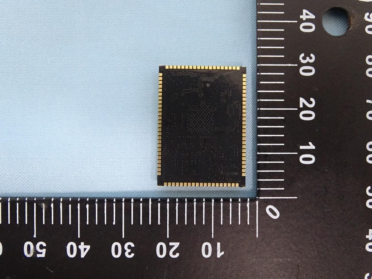
TX2-RTL8735BDM
Jan 11, 202411n RTL8735BDM combo module
Equipment Class
DTS - Digital Transmission System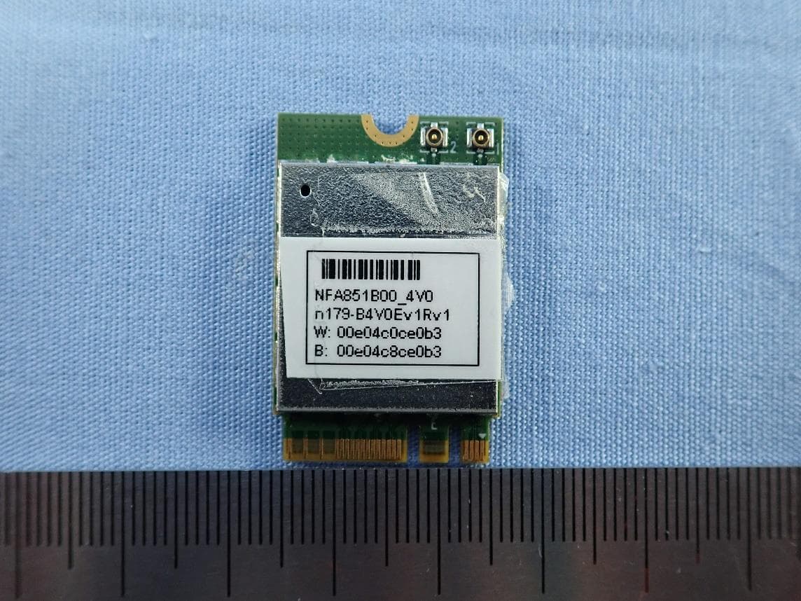
TX2-RTL8851BE
May 30, 202311ax RTL8851BE Combo module
Equipment Class
NII - Unlicensed National Information Infrastructure TX
TX2-RTL8852CE
Nov 20, 202211ax RTL8852CE Combo module
Equipment Class
DSS - Part 15 Spread Spectrum Transmitter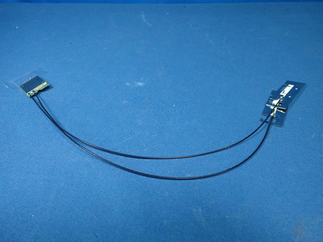
TX2-RTL8852AE
Oct 15, 202011ax RTL8852AE Combo module
Equipment Class
DSS - Part 15 Spread Spectrum Transmitter