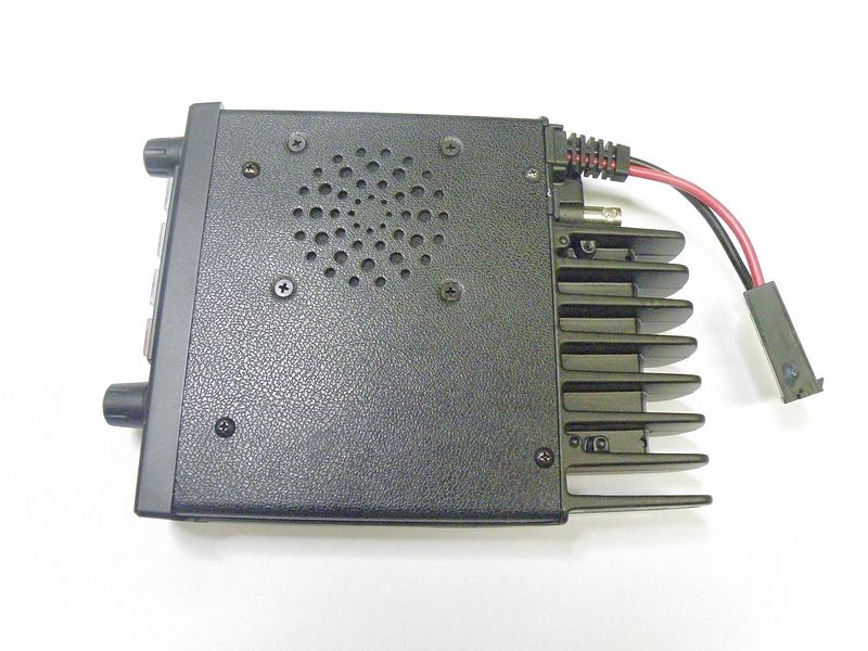
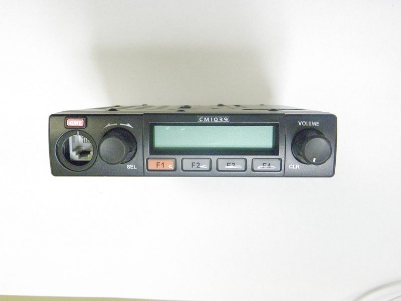
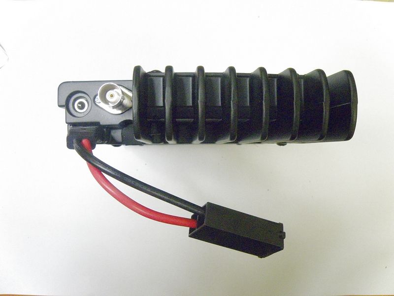
TXJCM1039URADIO TRANSCEIVER
Standard Communications Pty Ltd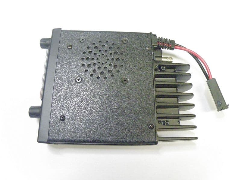
Click to zoom
Application Details
- Equipment Class
- TNB - Licensed Non-Broadcast Station Transmitter
- Date of Grant
- Apr 30, 2013
- Application Purpose
- Original Equipment
- Date of Application
- Apr 30, 2013
- Equipment Note
- RADIO TRANSCEIVER
- Frequency Range
- 450.00000000 - 512.00000000
- Country
- Australia
Documents & Files
Document Text
Text extracted from the exhibit documents filed with the FCC. Open a document above to read the original.
Users Manual
CM1039 PROFESSIONAL SERIES MOBILE RADIO INSTRUCTION MANUAL 2 Copyright Notice Standard Communications Pty Ltd reserves all rights to this document and the information contained herein. Reproduction, use or disclosure to third parties without the express permission is strictly prohibited. Copyright 2013 Standard Communications Pty Ltd Sydney, Australia RADIO FREQUENCY EXPOSURE HAZARD Attention This radio should be used only in an occupational (work related) environment where the user is aware of and able to exercise control over their exposure to RF energy. This radio is not authorized for use by the consumer or by the general population. To comply with the US FCC radio frequency guidelines and to ensure your safety please read the following information before installing and using the radio. • Use the radio only within the guidelines of this manual. • Use only with an approved antenna. • Do not remove the RF Exposure label from this radio. • Do not transit longer than the rated duty cycle of 50% talk‐50% listen. Radio Frequency Exposure Control This radio emits RF (Radio Frequency) energy or radio waves when transmitting. RF energy is one of many forms of electromagnetic energy including sunlight and electricity. The FCC Radio Frequency exposure guidelines include recommendations on the safe levels of exposure for workers and the general public with a significant margin of protection. To comply with FCC exposure limits the radio must be installed using an externally mounted antenna with a gain of either 2.15 dBi or 5.15 dBi. Transmit only when bystanders are at a minimum safe distance of 35 inches (0.9 m) from the antenna. For further information on RF energy exposure and how to control it, please visit the following website. www.fcc.gov/oet/rfsafety/rf‐faqs.html 3 Compliance with RF Energy Standards This radio is designed and tested to comply with a number of national and international standards and guidelines (listed below) regarding human exposure to RF electromagnetic energy. This radio complies with the IEEE and ICNIRP exposure limits for occupational/controlled RF exposure environment at duty cycles of up to 50% talk‐50% listen and should be used for occupational use only. In terms of measuring RF energy for compliance with the FCC exposure guidelines, your radio radiates measureable RF energy only when it is transmitting (during talking), not when it is receiving (listening) or in standby mode. This radio complies with the following RF energy exposure standards and guidelines: • United States Federal Communications Commission, Code of Federal Regulations; 47CFR part 2 sub‐part J • American National Standards Institute (ANSI)/Institute of Electrical and Electronic Engineers (IEEE) C95. 1‐1992 • Institute of Electrical and Electronic Engineers (IEEE) C95. 1‐1999 edition • International Commission on Non‐Ionizing Radiation Protection (ICNIRP) 1998 FCC COMPLIANCE This equipment has been tested and found to comply with the limits for a Class B digital device, pursuant to part 15 of the FCC Rules. These limits are designed to provide reasonable protection against harmful interference in a residential installation. This equipment generates uses and can radiate radio frequency energy and, if not installed and used in accordance with the instructions, may cause harmful interference to radio communications. However, there is no guarantee that interference will not occur in a particular installation. If this equipment does cause harmful interference to radio or television reception, which can be determined by turning the equipment off and on, the user is encouraged to try to correct the interference by one or more of the following measures: • Reorient or relocate the receiving antenna. • Increase the separation between the equipment and receiver. • Connect the equipment into an outlet on a circuit different from that to which the receiver is connected. Consult the dealer or an experienced radio/TV technician for help. 4 USING THE RADIO IN EXPLOSIVE ATMOSPHERES OR BLASTING AREAS Switch off your radio before entering any area where there may be inflammable gas, liquids or dust. An explosion could result in serious injury or death. Switch off your radio when approaching a blasting area. Blasting areas are usually sign posted with instructions to users to turn off two way radios. Strong radio transmissions could ignite blasting caps resulting in an unscheduled explosion resulting in serious injury or death. INSTALLATION GUIDELINES • Do not install the radio near an airbag or in an area where an airbag may deploy. If an airbag is obstructed by the radio, it may not deploy as expected. It could also propel the radio with enough force to cause serious injury. • Avoid touching the heat sink at the rear of the radio while the radio is in use. The heat sink can become hot during prolonged use. • Do not install the radio in front of a vehicle heater. The radio requires a cool airflow over the rear heat sink when transmitting to maintain efficiency. • Do not make unapproved modifications to the radio. Such modifications could void the warranty and cause the radio to operate outside its approved specifications. Interference with Vehicle Electronics Some of the electronics in your vehicle may be susceptible to RF energy when your radio is transmitting. Examples of electronic devices in your vehicle that could be affected are anti‐ lock/anti‐skid braking systems, cruise control systems and fuel injection systems. If your vehicle is fitted with any of these systems please consult your vehicle manufacturer to determine whether these systems are likely to be affected by your radio when it is transmitting. Careful selection of mounting locations and good installation techniques should generally minimize any interference to your vehicle electronics. 5 CONTENTS INTRODUCTION. . . . . . . . . . . . . . . . . . . . . . . . . . . . . . . . . . . . . . . . . . . . . . . . . . . . . . . . . . . 6 FEATURES. . . . . . . …
Text truncated - open the document above for the full version.
Cover Letter(s)
22 nd April 2013 Federal Communications Commission Authorization and Evaluation Division Subject: Part 90.203 (j) (5) Certification Statement – FCC ID: TXJCM1039U Standard Communications Pty. Ltd. certifies that it’s digital mobile transceiver FCC ID: TXJCM1039U, meets a spectrum efficiency standard of one voice channel per 6.25 kHz of channel bandwidth. Additionally, Standard Communications Pty. Ltd certifies the equipment is capable of supporting a minimum data rate of 4800 bits per second per 6.25 kHz of channel bandwidth. Sincerely, Kevan Wilson-Elswood ( Technical Compliance Manager)
Cover Letter(s)
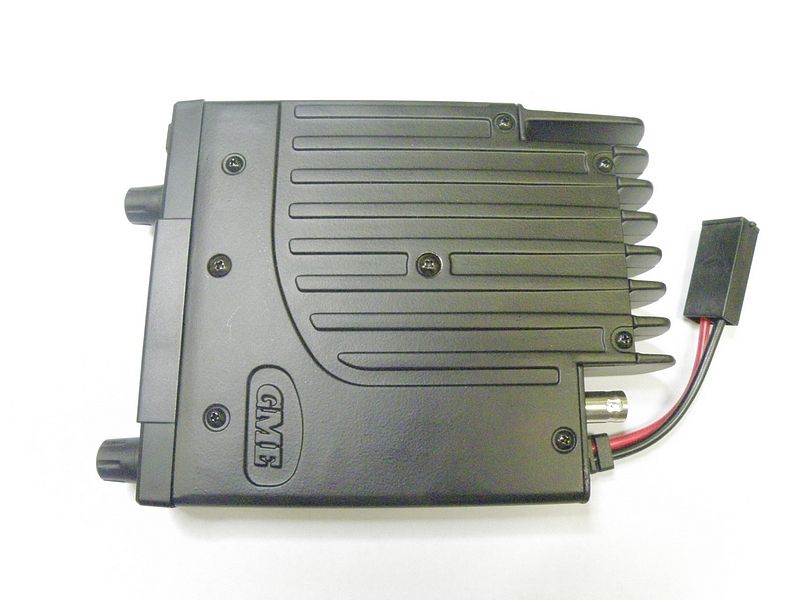
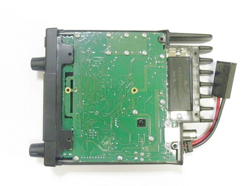
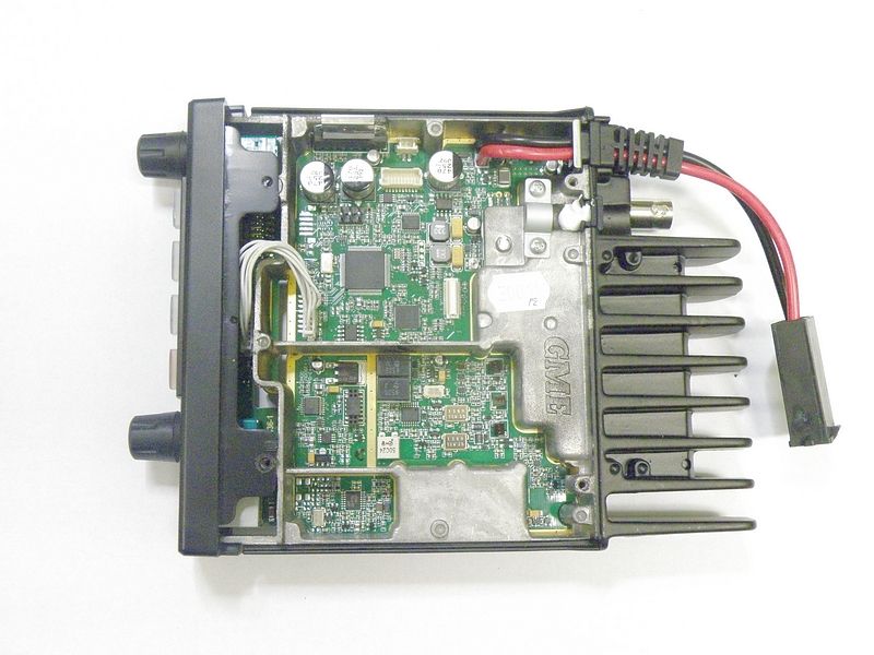
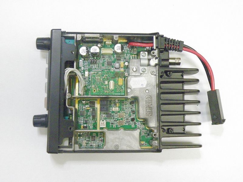
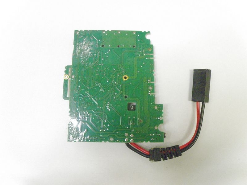
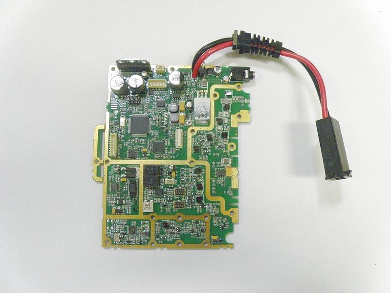
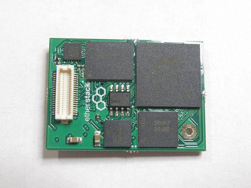
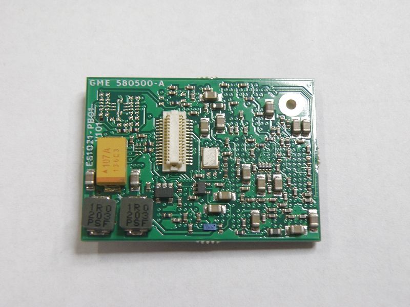
22 nd April 2013 Federal Communications Commission Authorization and Evaluation Division Confidentiality Request regarding application for certification of FCC ID: TXJCM1039U. Pursuant to Sections 0.457 and 0.459 of the Commission’s Rules, we hereby request confidential treatment of information accompanying this application as outlined below: Exhibit Type Block Diagram Schematic Schematic Schematic Circuit Description Tuning Procedure Parts List File Name CM1039U Block Diagram.pdf CM1039U Schematic Diagram.pdf CM1039U Front Panel Schematic.pdf CM1039 P25 Module schematic.pdf CM1039U Circuit Description.pdf CM1039U Tuning Procedure.pdf CM1039U Parts List.pdf The above materials contain trade secrets and proprietary information not customarily released to the public. The public disclosure of these materials may be harmful to the applicant and provide unjustified benefits to its competitors. The applicant understands that pursuant to Section 0.457 of the Rules, disclosure of this application and all accompanying documentation will not be made before the date of the Grant for this application. Pursuant to DA04-1705 June 15, 2004 of the Commission’s public notice, we also request temporary confidential treatment of information accompanying this application as outlined below: Exhibit Type Internal Photos Operating Manual File Name CM1039U Internal - Top Cover Removed.jpg CM1039U Internal Bottom (no module).JPG CM1039U Internal Bottom ( with module).jpg CM1039U PCB Bottom.jpg CM1039U PCB Top.jpg P25 Module Bottom.jpg P25 Module Top.jpg CM1039 USA Instruction Manual.pdf Sincerely, Kevan Wilson-Elswood ( Technical Compliance Manager)
RF Exposure Info
Page 1 of 3 RF Exposure Requirements General information : Device category: Fixed per Part 2.1091 Environment: Uncontrolled Exposure Fixed devices that operate under Part 90 of this chapter are subject to routine environmental evaluation for RF exposure prior to equipment authorization or use if they operate at frequencies of 1.5 GHz or below and their effective radiated power (ERP) is 1.5 watts or more. However, compliance with the power density limits of 1.1310 is not required. Antenna: The manufacturer does not specify an antenna. A typical mobile installation antenna has a gain of 5 dBi. This device has provisions for operation only as a mobile mounted device. Configuration Antenna p/n Type Max. Gain (dBi) mobile Any omni 5 Operating configuration and exposure conditions: The conducted output power is 25 Watts. In normal PTT operation the duty cycle is approximately 50%. The manufacturer also markets this device only for occupation use. But, typical installations may not control exposure. - Part 2.1091 states that devices are excluded from routine evaluation if the EIRP is less than 2.46Watt (or 1.5WERP). - A typical mobile installation consists of an antenna system with a coaxial cable of the type RG 213U which has a loss of 1.0 dB for a length of 30 feet at UHF frequencies. MPE Calculation : The minimum separation distance is calculated as follows: The limit for uncontrolled exposure environment above 300 MHz is f/1500 mW/cm 2 . Page 2 of 3 Frequency: 450-512 MHz The conducted power output is 25 Watt. The coax loss was taken as 1.0 dB. Antenna gain was taken as 5 dBi 50% Duty Factor Power Density = S= f/1500 mW/cm 2 Page 3 of 3 Conclusion: The device complies with the MPE requirements by providing a safe separation distance of 93cm 37 inches) between the antenna, including any radiating structure, and any persons when normally operated . The minimum safe operating distance between the public and the antenna should be at least 93 cm (37 inches) when used with a 3 dBi antenna.
Test Report
FCC PART 90 TEST REPORT APPLICANT STANDARD COMMUNICATIONS Pty.Ltd. Locked Bag 2086 Nth Ryde NSW 1670 AUSTRALIA FCC ID TXJCM1039U MODEL NUMBER CM1039U PRODUCT DESCRIPTION RADIO TRANSCEIVER DATE SAMPLE RECEIVED 2/25/2013 DATE TESTED 3/15/2013 TESTED BY Nam Nguyen APPROVED BY Mario de Aranzeta TIMCO REPORT NO. 351AUT13TestReport.doc TEST RESULTS PASS FAIL THE ATTACHED REPORT SHALL NOT BE REPRODUCED EXCEPT IN FULL WITHOUT THE WRITTEN APPROVAL OF TIMCO ENGINEERING, INC. TABLE OF CONTENTS 849 NW STATE ROAD 45 NEWBERRY, FL 32669 USA PH: 888.472.2424 OR 352.472.5500 FAX: 352.472.2030 EMAIL: [email protected] HTTP://WWW.TIMCOENGR.COM Certificate # 0955-01 Applicant: STANDARD COMMUNICATIONS Pty.Ltd. FCC ID: TXJCM1039U Report: s\STANDARD Comm Au\351AUT13\351AUT13TestReport.doc Page 2 of 29 TABLE OF CONTENTS GENERAL REMARKS ........................................................................................................3 GENERAL INFORMATION .................................................................................................4 TEST PROCEDURES ........................................................................................................5 RF POWER OUTPUT .........................................................................................................6 MODULATION CHARACTERISTICS ...................................................................................7 AUDIO FREQUENCY RESPONSE ......................................................................................8 AUDIO LOW PASS FILTER ................................................................................................9 AUDIO INPUT VERSUS MODULATION ............................................................................ 10 OCCUPIED BANDWIDTH ................................................................................................ 11 SPURIOUS EMISSIONS AT ANTENNA TERMINALS (CONDUCTED) ................................... 19 FIELD STRENGTH OF SPURIOUS EMISSIONS ................................................................ 22 FREQUENCY STABILITY ................................................................................................. 25 TRANSIENT FREQUENCY BEHAVIOR ............................................................................. 26 EMC EQUIPMENT LIST .................................................................................................. 29 Applicant: STANDARD COMMUNICATIONS Pty.Ltd. FCC ID: TXJCM1039U Report: s\STANDARD Comm Au\351AUT13\351AUT13TestReport.doc Page 3 of 29 GENERAL REMARKS The attached report shall not be reproduced except in full without the written permission of Timco Engineering Inc. The test results relate only to the items tested. Summary The device under test does: fulfill the general approval requirements as identified in this test report not fulfill the general approval requirements as identified in this test report Attestations This equipment has been tested in accordance with the standards identified in this test report. To the best of my knowledge and belief, these tests were performed using the measurement procedures described in this report. All instrumentation and accessories used to test products for compliance to the indicated standards are calibrated regularly in accordance with ISO 17025: 2005 requirements. Testing Certificate # 0955-01 I attest that the necessary measurements were made, under my supervision, at: Timco Engineering Inc. 849 NW State Road 45 Newberry, Fl 32669 Authorized Signatory Name: Nam Nguyen Project Manager/Testing Technician Mario de Aranzeta C.E.T. Compliance Engineer/ Lab. Supervisor Date: April 30, 2013 Applicant: STANDARD COMMUNICATIONS Pty.Ltd. FCC ID: TXJCM1039U Report: s\STANDARD Comm Au\351AUT13\351AUT13TestReport.doc Page 4 of 29 GENERAL INFORMATION DUT Specification DUT Description RADIO TRANSCEIVER FCC ID TXJCM1039U Model Number CM1039U Serial Number N/A Operating Frequency 450 – 512 MHz Test Frequencies 450.1, 481.1, and 511.9 MHz Type of Emission 11K0F3E, 7K60F1D, 7K60F1E 7K60F1W, 7K60FXE, 7K60FXD Modulation FM, 4FSK DUT Power Source 110–120Vac/50– 60Hz DC Power 12V Battery Operated Exclusively Test Item Prototype Pre-Production Production Type of Equipment Fixed Mobile Portable Test Conditions The temperature was 26ºC with a relative humidity of 50% . Modification to the DUT None Test Exercise The DUT was placed in continuous transmit mode. Applicable Standards ANSI/TIA 603-C:2004, FCC CFR 47 Part 90, IC RSS- 119, RSS-GEN Test Facility Timco Engineering Inc. at 849 NW State Road 45 Newberry, FL 32669 USA. Applicant: STANDARD COMMUNICATIONS Pty.Ltd. FCC ID: TXJCM1039U Report: s\STANDARD Comm Au\351AUT13\351AUT13TestReport.doc Page 5 of 29 TEST PROCEDURES Power Line Conducted Interference: The procedure used was ANSI/TIA 603-C:2004 using a 50uH LISN. Both lines were observed with the DUT transmitting. The bandwidth of the spectrum analyzer was 10 kHz with an appropriate sweep speed. Bandwidth 20 dB: The measurements were made with the spectrum analyzer's resolution bandwidth (RBW) = 1 MHz and the video bandwidth (VBW) = 3 MHz and the span set as shown on plot. Power Output: The RF power output was measured at the antenna feed point using a peak power meter. Antenna Conducted Emissions: The RBW = 100 kHz, VBW = 300 kHz and the span set to 10.0 MHz and the spectrum was scanned from 30 MHz to the 10 th harmonic of the fundamental. Above 1 GHz the resolution bandwidth was 1 MHz and the VBW = 3 MHz and the span to 50 MHz. Radiation Interference: The test procedure used was ANSI/TIA 603-C:2004 using an Agilent spectrum receiver with pre-selector. The bandwidth (RBW) of the spectrum receiver was 100 kHz up to 1 GHz and 1 MHz above 1 GHz with an appropriate sweep speed. The VBW above 1 GHz was 3 MHz. The analyzer was calibrated in dB above a micro volt at the output of the antenna. Applicant: STANDARD COMMUNICATIONS Pty.Ltd. FCC ID: TXJCM1039U Report: s\STANDARD Comm Au\351AUT13\351AUT13TestRepo…
Text truncated - open the document above for the full version.
Contact Information
Applicant
Filip Zalio(General Manager - Engineering)
Test Firm
Timco Engineering, Inc.Bruno Clavier
Technical Specifications
| # | Rule Parts | Frequency Range | Power Output | Emission | Tolerance |
|---|---|---|---|---|---|
| 12 | 9 | 450 MHz - 512 MHz | 1 W | 7K60FXD | 0.54 ppm |
Other Applications from Standard Communications Pty Ltd
TXJ-XRS660U
Jul 29, 2026XRS Connect Handheld UHF GMRS Radio
Equipment Class
TNF - Licensed Non-Broadcast Transmitter Held to Face
TXJ-GX510
Dec 10, 2025GMDSS Handheld VHF Radio
Equipment Class
TNF - Licensed Non-Broadcast Transmitter Held to Face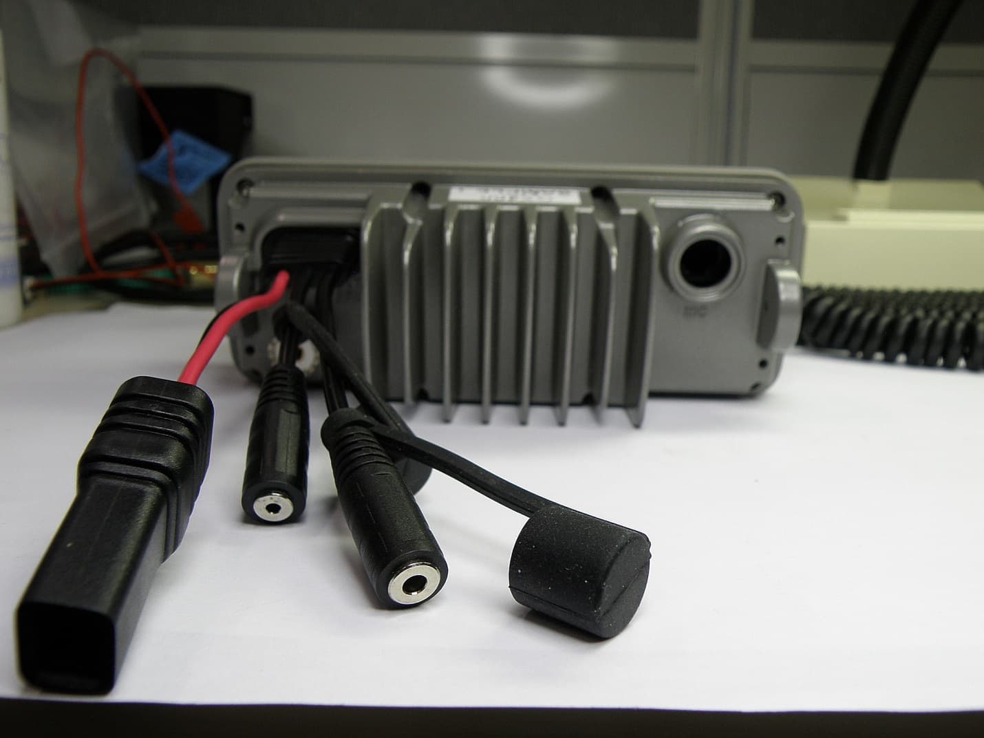
TXJGX400
Dec 28, 2014HF CB TRANSCEIVER
Equipment Class
TNB - Licensed Non-Broadcast Station Transmitter
TXJMT403-G
Apr 16, 2008MT403/403G/403FF/403FG Class2 406MHz EPIRB
Equipment Class
GEP - 406 MHz EPIRB
TXJMT410-G
Sep 05, 2007Class 2 Category 1 406MHz PLB
Equipment Class
PLB - Personal Locator Beacons