TXJGX400HF CB TRANSCEIVER
Standard Communications Pty Ltd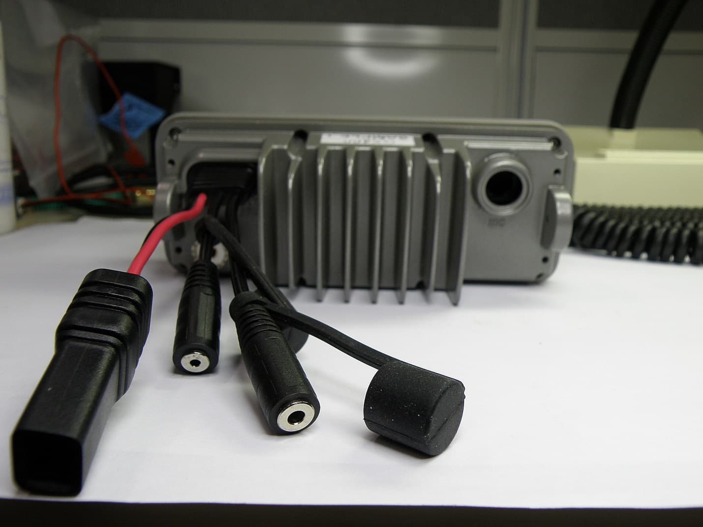
Click to zoom
Application Details
- Equipment Class
- TNB - Licensed Non-Broadcast Station Transmitter
- Date of Grant
- Dec 28, 2014
- Application Purpose
- Original Equipment
- Date of Application
- Dec 25, 2014
- Equipment Note
- HF CB TRANSCEIVER
- Frequency Range
- 26.96500000 - 27.40500000
- Country
- Australia
Documents & Files
Document Text
Text extracted from the exhibit documents filed with the FCC. Open a document above to read the original.
Users Manual
GX400 27 MHz MARINE RADIO INSTRUCTION MANUAL 2 InstructIon manual GX400 CONtENts WarnInG/saFEtY InFormatIon .....................................................................................................3 IntroDuctIon ................................................................................................................................3 InstallatIon GuIDElInEs ...............................................................................................................3 Interference with vehicle electronics ...........................................................................................3 FEaturEs ........................................................................................................................................4 sWItcHInG BanDs ..........................................................................................................................4 controls ........................................................................................................................................4 GEnEral opEratIon .......................................................................................................................6 Volume on/off ...........................................................................................................................6 squelch control .........................................................................................................................6 channel selection ......................................................................................................................6 Display brightness .....................................................................................................................6 transmitting ..............................................................................................................................6 noise limiter .............................................................................................................................6 scanning ...................................................................................................................................7 priority channels (pr1/pr2) ........................................................................................................8 Key lock function ......................................................................................................................8 opEratIon on tHE australIan marInE BanD .............................................................................8 Dual Watch (marine mode) ........................................................................................................8 triple Watch (marine mode).......................................................................................................9 triple Watch features ................................................................................................................9 marine Band procedures ..........................................................................................................10 Emergency procedures .............................................................................................................10 opEratIon on tHE cB BanD ........................................................................................................11 Dual Watch (cB mode) ............................................................................................................11 triple Watch (cB mode) ...........................................................................................................12 triple Watch features ..............................................................................................................12 InstallatIon ................................................................................................................................14 General ...................................................................................................................................14 Installing the unit ....................................................................................................................14 Dc connections .......................................................................................................................15 antenna installation ................................................................................................................16 Extension speaker ...................................................................................................................16 noise suppression ...................................................................................................................16 Disconnecting the microphone .................................................................................................17 spEcIFIcatIons .............................................................................................................................18 stanDarD communIcatIons WarrantY aGaInst DEFEcts ..........................................19 GX400 InstructIon manual 3 WARNING/sAFEtY INFORMAtION the GX400 is a radio transmitting device. • Do not transmit near electrical blasting equipment or in explosive atmospheres. • Do not allow children to operate a radio transmitter unsupervised. • the antenna used for this radio must be properly installed and maintained and must provide a separation distance of at least 34 cm (13.4 inches) from all persons and must not be collocated or operated in conjunction with any other antenna or transmitter. never transmit if any person is closer than the specified distance to the antenna. • changes or modifications to this product or use of accessories not expressly approved by GmE, or operation of this product in any way other than as provided in the GmE owner’s manual could void your authority to operate this product. INtRODUCtION congratulations. You have just purchased one of the most technically …
Text truncated - open the document above for the full version.
Users Manual
ADDENDUM FOR USERS IN THE UNITED STATES OF AMERICA Standard Communications Pty Ltd Hereby certifies that this unit has been designed, manufactured, FCC type accepted and certified in accordance with part 95 and Part 15, Subpart C of the current FCC rules and regulations as of the date of manufacture. Warning: Do not attempt to make any internal adjustments. Internal adjustments and/or modifications can lead to illegal operation as defined by the FCC rules and regulations, Part 95. They must be made only by qualified technical personnel. Illegal operation can lead to serious consequences. Be sure to read and understand Part 95, FCC Rules and Regulations, before operating your transmitter. Changes or modifications to this product or use of accessories not expressly approved by GME, or operation of this product in any way other than as provided in the GME Instruction Manual could void your authority to operate this product. The Citizens Band Radio Service is under the jurisdiction of the Federal Communications Commission (FCC). Any adjustments or alterations which would alter the performance of the transceiver's original FCC type acceptance, or which would change the frequency determining method, are strictly prohibited. Replacement or substitution of crystal, transistors, ICs, regulator diodes, or any other part of a unique nature, with parts other than those recommend by GME, may cause violations of the technical regulations in Part 95 of the FCC Rules or in violation of type acceptance requirements in Part 2 of the rules. All channels except Channel 9 may be used for normal communication. The FCC reserves Channel 9 for emergencies involving the immediate safety of individuals or protection of property. Use Channel 9 to render assistance to a motorist. This is an FCC rule and applies to all CB radio operators. SAFETY NOTICE The antenna used for this radio must be properly installed and maintained and must provide a separation distance of at least 20 cm (8 Inches) from all persons and must not be collocated or operated in conjunction with any other antenna or transmitter. Never transmit if any person is closer than the specified distance to the antenna. The above limit applies to any antenna with up to 3 dBi gain. WARRANTY – NORTH AMERICA Standard Communications Pty Ltd (herein, GME) warrants each new radio product manufactured or supplied by it to be free from defects in material and workmanship under normal use and service for a period listed below, provided that the user has complied with the requirements stated herein. The Warranty period begins on the date of purchase from an authorized GME Sales and Service Outlet. This warranty is offered to the original end user and is not assignable or transferable. GME is not responsible for any ancillary equipment attached to or used in conjunction with its products. GME offers to the original end user a One (1) Year Limited Warranty on the GX400 27 MHz Transceiver. During this period, if the product fails to function under normal use through manufacturing defect(s) or substandard workmanship, it should be returned to the authorized GME Sales and Service Outlet from which it was purchased. The Sales and Service Outlet will repair the product or return the product for repair to GME or its authorized Regional Repair Depot. The user is responsible for the payment of any charges or expenses incurred for the removal of the defective product from the vehicle or other location of its use; for the transportation of the product to the Sales and Service Outlet; for the return of the repaired / replacement product to the location of its use and for the reinstallation of the product. GME shall have no obligation to make repairs or to provide replacement product, which results from normal wear and tear or is necessitated in whole or in part by catastrophe, fault or negligence of the user, improper or unauthorized alterations or repairs to the product, incorrect wiring, use of the product in a manner for which it was not designed or by causes external to the product. This Warranty is void if the product serial number is altered, defaced or removed. GME’s sole obligation hereunder shall be to replace or repair the product covered in this warranty. Replacement, at GME’s discretion, may include a similar or higher-featured product. Repair may include the replacement of parts or boards with functionally equivalent reconditioned or new parts and/or boards. No repair undertaken or replacement product provided during the warranty period will renew or extend the warranty period past the period from the original date of purchase. All replaced parts, electronic components or boards become the property of GME. THE EXPRESS WARRANTIES CONTAINED HEREIN ARE IN LIEU OF ALL OTHER WARRANTIES, EITHER EXPRESSED OR IMPLIED OR STATUTORY, INCLUDING, WITHOUT LIMITATION, ANY WARRANTY OF MERCHANTABILITY OR FITNESS FOR A PARTICULAR PURPOSE. FOR ANY PRODUCT WHICH DOES NOT COMPLY WITH THE WARRANTY SPECIFIED, THE SOLE REMEDY WILL BE REPAIR OR REPLACEMENT. IN NO EVENT WILL GME BE LIABLE TO THE BUYER OR ITS CUSTOMERS FOR ANY DAMAGES, INCLUDING ANY SPECIAL, INCIDENTAL, INDIRECT OR CONSEQUENTIAL DAMAGES, OR FOR THE LOSS OF PROFIT, REVENUE OR DATA ARISING OUT OF THE USE OF OR THE INABILITY TO USE THE PRODUCT. This warranty is void for sales and deliveries outside of the U. S. A. and Canada. FCC RULES PART 95 Data is current as of August 4, 2014 Subpart D—Citizens Band (CB) Radio Service SOURCE: 48 FR 24894, June 3, 1983, unless otherwise noted. GENERAL PROVISIONS §95.401 (CB Rule 1) What are the Citizens Band Radio Services? The Citizens Band Radio Services are: (a) The Citizens Band (CB) Radio Service—a private, two-way, short-distance voice communications service for personal or business activities of the general public. The CB Radio Service may also be used for voice paging. (b) The Family Radio Service (FRS)—a private, two-way, very short-distance voice and data communications service for …
Text truncated - open the document above for the full version.
Cover Letter(s)
15 th October 2014 Federal Communications Commission Authorization and Evaluation Division Confidentiality Request regarding application for certification of FCC ID: TXJGX400 Pursuant to Sections 0.457 and 0.459 of the Commission’s Rules, we hereby request confidential treatment of information accompanying this application as outlined below: Exhibit Type Block Diagram Schematic PCB Overlay Circuit Description Tuning Procedure File Name TXJGX400 Block Diagram.pdf TXJGX400 Circuit.pdf TXJGX400 PCB Layout.pdf TXJGX400 Circuit Description.pdf TXJGX400 Tuning Procedure.pdf The above materials contain trade secrets and proprietary information not customarily released to the public. The public disclosure of these materials may be harmful to the applicant and provide unjustified benefits to its competitors. The applicant understands that pursuant to Section 0.457 of the Rules, disclosure of this application and all accompanying documentation will not be made before the date of the Grant for this application. Pursuant to DA04-1705 June 15, 2004 of the Commission’s public notice, we also request temporary confidential treatment of information accompanying this application as outlined below: Exhibit Type Internal Photos Operating Manual File Name TXJGX400 Front Panel PCB - front.JPG TXJGX400 Front Panel PCB - rear.JPG TXJGX400 RF PCB Bottom_No Shield.JPG TXJGX400 RF PCB Bottom_with shield.JPG TXJGX400 RF PCB Top_In chassis with shield.JPG TXJGX400 RF PCB Top_No shield.JPG TXJGX400 RF PCB Top_with shield.JPG TXJGX400_Instruction Manual_Rev_A.pdf TXJGX400 USA Addendum Rev_A.pdf Sincerely, Kevan Wilson-Elswood ( Technical Compliance Manager)
External Photos
APPLICANT: STANDARD COMMUNICATIONS PTY. LTD. FCC ID: TXJGX400 EXTERNAL PHOTOS
ID Label/Location Info
Standard Communications Pty Ltd. 17 Gibbon Road, Winston Hills, NSW 2153, Australia www.gme.net.au FCC ID: TXJGX400 FCC ID: TXJGX400 GX400 Compliance Label 1 of 1 1 : 1 mm AT 401301 7/08/2014 46759 1 IL 46759-1_GX400_CompLabel.indd GX400 Compliance Label 10.00 mm 10.00 mm 10.00 mm 32.00 mm 32.00 mm 32.00 mm Artwork and Knife Artwork Only Knife Only Model GX400 Model GX400 Designed in Australia by: Standard Communications Pty Ltd Designed in Australia by: Standard Communications Pty Ltd Made in China Made in China Serial No. Serial No. ARTWORK APPROVED Graphics Date Sales Engineering Description: Sheet: Scale: Units: Drawn by: Part Number: Date: Drawing Number: Issue No: Engineer: File Name:
ID Label/Location Info
GX400 Label Locations
Internal Photos
APPLICANT: STANDARD COMMUNICATIONS PTY. LTD. FCC ID: TXJGX400 INTERNAL PHOTOS
RF Exposure Info
RF Exposure Evaluation Report APPLICANT STANDARD COMMUNICATIONS PTY.LTD. PO BOX 96 WINSTON HILLS NSW 2153 AUSTRALIA FCC ID TXJGX400 MODEL NUMBER GX400 PRODUCT DESCRIPTION MARINE CB TRANSCEIVER STANDARD APPLIED CFR 47 Part 2.1091 PREPARED BY Cory Leverett We, TIMCO ENGINEERING, INC. would like to declare that the device has been evaluated in accordance with 47 CFR Part 2.1091 and meets the requirements. The attached report shall not be reproduced except in full without the written approval of TIMCO ENGINEERING, INC. 849 NW STATE ROAD 45 NEWBERRY, FL 32669 USA PH: 888.472.2424 OR 352.472.5500 FAX: 352.472.2030 EMAIL: [email protected] HTTP://WWW.TIMCOENGR.COM Applicant: STANDARD COMMUNICATIONS PTY.LTD. FCC ID: TXJGX400 Report: s\STANDARD Comm Au\1842AUT14\1842AUT14TestReport.docxt Page 2 of 4 GENERAL REMARKS Attestations This equipment has been evaluated in accordance with the standards identified in this report. To the best of my knowledge and belief, these evaluations were performed using the procedures described in this report. I attest that the necessary evaluations were made, under my supervision, at: Timco Engineering Inc. 849 NW State Road 45 Newberry, Fl 32669 Authorized Signatory Name: Cory Leverett Engineering Project Manager Date: 12/26/2014 Applicant: STANDARD COMMUNICATIONS PTY.LTD. FCC ID: TXJGX400 Report: s\STANDARD Comm Au\1842AUT14\1842AUT14TestReport.docxt Page 3 of 4 RF Exposure Requirements General information Device type: Part 95 CB Transceiver. Antenna The manufacturer does not specify an antenna, but a typical antenna has a gain of 0 dBi. Configuration Antenna p/n Type Max. Gain (dBi) Fixed mounted Any omni 0 Operating configuration and exposure conditions: The conducted output power is shown in the table below. Typical use qualifies for a maximum duty cycle factor of 100%. Operation: A typical installation consists of an antenna system with a 10 meter coaxial cable of the type RG 213/ U type which has a loss as follows; Nom. Attenuation for RG 213/U: Frequency MHz Attenuation per 100ft. dB 1 .27 10 .55 50 1.3 100 1.9 200 2.7 400 4.1 700 6.5 900 7.6 1000 8.0 4000 21.5 MPE Calculation: The minimum separation distance is calculated as follows: Applicant: STANDARD COMMUNICATIONS PTY.LTD. FCC ID: TXJGX400 Report: s\STANDARD Comm Au\1842AUT14\1842AUT14TestReport.docx The limit for general uncontrolled exposure environment is shown in FCC rule Part 1.11310, Table 1. Max Power 4 Wequals Max Power 4000 mW Duty Cycle 50% equalsDuty Factor 0.5numeric Antenna Gain0 dBiequalsGain numeric1 numeric Coax Loss 0.55dB Gain - Coax Los0.881049numeric Power Density 0.24 mW/cm 2 Frequency27.405 MHz Frequency rangPower denEnter this value MHz mW/cm 2 mW/cm 2 0.3-1.34100 100 1.34-30 180/f 2 0.2 30-3000.2 0.2 300-1,500f/15000.0 1,500-100,00011 f = frequency in MHz Minimum Separation Distance 24cm0.24m Minimum Seperation in Inches9.509087 Inches Minimum Separation Distance for Mobile or Fixed Devices General Population/Uncontrolled Exposure Insert values in yellow highlighted boxes to determine Minimum Separation Distance Enter power Density from the chart to the rightRule Part 1.1310, Table 1
Test Report
FCC PART 95 SUBPART D TEST REPORT FOR CB TRANSCEIVERS APPLICANT STANDARD COMMUNICATIONS PTY.LTD. PO BOX 96 WINSTON HILLS NSW 2153 AUSTRALIA FCC ID TXJGX400 MODEL NUMBER GX400 PRODUCT DESCRIPTION MARINE CB TRANSCEIVER DATE SAMPLE RECEIVED 10/13/2014 DATE TESTED 12/17/2014 TESTED BY Cory Leverett APPROVED BY Sid Sanders TIMCO REPORT NO. 1842AUT14TestReportRev1.docx TEST RESULTS PASS FAIL THE ATTACHED REPORT SHALL NOT BE REPRODUCED EXCEPT IN FULL WITHOUT THE WRITTEN APPROVAL OF TIMCO ENGINEERING, INC. 849 NW STATE ROAD 45 NEWBERRY, FL 32669 USA PH: 888.472.2424 OR 352.472.5500 FAX: 352.472.2030 EMAIL: [email protected] HTTP://WWW.TIMCOENGR.COM Table of Contents Contents GENERAL REMARKS .................................................................................................... 3 GENERAL INFORMATION ............................................................................................. 4 TEST ENVIRONMENT ................................................................................................... 5 TEST SETUP SUMMARY ............................................................................................... 5 TEST PROCEDURES ..................................................................................................... 6 RF POWER OUTPUT ..................................................................................................... 7 MODULATION CHARACTERISTICS .............................................................................. 8 AUDIO FREQUENCY RESPONSE .................................................................................. 8 AUDIO LOW PASS FILTER RESPONSE ......................................................................... 9 AUDIO INPUT VS MODULATION ................................................................................ 10 OCCUPIED BANDWIDTH ........................................................................................... 11 SPURIOUS EMISSIONS AT ANTENNA TERMINALS (CONDUCTED) ........................... 13 Test Data: Table of Emissions ........................................... 13 RADIATED SPURIOUS EMISSIONS ........................................................................... 14 RADIATED SPURIOUS EMISSIONS ........................................................................... 15 Test Data: Table of Emissions ........................................... 15 Results Meet Requirements ...................................................................................... 15 FREQUENCY STABILITY ............................................................................................. 16 EQUIPMENT LIST....................................................................................................... 17 APPLICANT: STANDARD COMMUNICATIONS PTY.LTD. FCC ID: TXJGX400 REPORT #: s\STANDARD Comm Au\1842IC14\184AUT14TestReportRev1 .docx Page 2 of 17 GENERAL REMARKS The attached report shall not be reproduced except in full without the written permission of Timco Engineering Inc. The test results relate only to the items tested. Summary The device under test does: fulfill the general approval requirements as identified in this test report not fulfill the general approval requirements as identified in this test report Attestations This equipment has been tested in accordance with the standards identified in this test report. To the best of my knowledge and belief, these tests were performed using the measurement procedures described in this report. All instrumentation and accessories used to test products for compliance to the indicated standards are calibrated regularly in accordance with ISO 17025 requirements. I attest that the necessary measurements were made, under my supervision, at: Timco Engineering Inc. 849 NW State Road 45 Newberry, Fl 32669 Authorized Signatory Name: Cory Leverett Engineering Project Manager Date: 12/17/2014 Table of Contents APPLICANT: STANDARD COMMUNICATIONS PTY.LTD. FCC ID: TXJGX400 REPORT #: s\STANDARD Comm Au\1842IC14\184AUT14TestReportRev1 .docx Page 3 of 17 GENERAL INFORMATION EUT Specification EUT Description MARINE CB TRANSCEIVER FCC ID TXJGX400 Model Number GX400 Serial Number N/A Operating Frequency 26.965-27.405 MHz TEST FREQUENCY Ch 21 27.215 MHz Ch 20 27.205 MHz No. of Channels 40 Type of Emission 6KOOA3E Bn = 2M M = 3000 Bn = 6000 Modulation AM EUT Power Source 110–120Vac/50– 60Hz DC Power Battery Operated Exclusively Test Item Prototype Pre-Production Production Type of Equipment Fixed Mobile Portable Table of Contents APPLICANT: STANDARD COMMUNICATIONS PTY.LTD. FCC ID: TXJGX400 REPORT #: s\STANDARD Comm Au\1842IC14\184AUT14TestReportRev1 .docx Page 4 of 17 TEST ENVIRONMENT Test Facility Timco Engineering, Inc. 849 NW State Road 45 Newberry, FL 32669 USA. Test Condition in the laboratory Temperature: 26ºC Relative humidity: 50% TEST SETUP SUMMARY Test Setup Diagram/ Description The EUT was placed on the turntable per setup per ANSI C63.4: 2003. A test set up photo is provided for clarification. Deviation from the standard/procedure No deviation Modification of EUT No modification Applicable Standards EIA/TIA-382-A, FCC CFR 47 PART 95 Table of Contents APPLICANT: STANDARD COMMUNICATIONS PTY.LTD. FCC ID: TXJGX400 REPORT #: s\STANDARD Comm Au\1842IC14\184AUT14TestReportRev1 .docx Page 5 of 17 TEST PROCEDURES Power Line Conducted Interference: The procedure used was EIA/TIA-382-A using a 50uH LISN. Both lines were observed with the UUT transmitting. The bandwidth of the spectrum analyzer was 10 kHz with an appropriate sweep speed. Bandwidth 20 dB: The measurements were made with the spectrum analyzer's resolution bandwidth (RBW) = 1 MHz and the video bandwidth (VBW) = 3 MHz and the span set as shown on plot. Power Output: The RF power output was measured at the antenna feed point using a peak power meter. Antenna Conducted Emissions: The RBW = 100 kHz, VBW = 300 kHz and the span set to 10.0 MHz and the spectrum was scanned from 30 MHz to the 10 th Harmonic of the funda…
Text truncated - open the document above for the full version.
Test Setup Photos
APPLICANT: STANDARD COMMUNICATIONS PTY. LTD. FCC ID: TXJGX400 TEST SET UP PHOTOS
Contact Information
Applicant
Filip Zalio(General Manager - Engineering)
Technical Contact
Timco Engineering, Inc.Cory Leverett
[email protected]888-472-2424
849 NW State Road 45 · Newberry, Florida · United States
Non-Technical Contact
Timco Engineering, Inc.Sharon Hoffman
[email protected]888-472-2424
Test Firm
Timco Engineering, Inc.Bruno Clavier
Technical Specifications
| # | Rule Parts | Frequency Range | Power Output | Emission | Tolerance |
|---|---|---|---|---|---|
| 1 | 95D | 26.965 MHz - 27.405 MHz | 4 W | 6K00A3E | 3.9400000000 ppm |
Other Applications from Standard Communications Pty Ltd
TXJ-XRS660U
Jul 29, 2026XRS Connect Handheld UHF GMRS Radio
Equipment Class
TNF - Licensed Non-Broadcast Transmitter Held to Face
TXJ-GX510
Dec 10, 2025GMDSS Handheld VHF Radio
Equipment Class
TNF - Licensed Non-Broadcast Transmitter Held to Face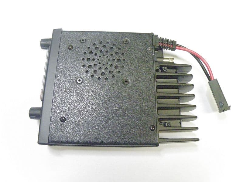
TXJCM1039U
Apr 30, 2013RADIO TRANSCEIVER
Equipment Class
TNB - Licensed Non-Broadcast Station Transmitter
TXJMT403-G
Apr 16, 2008MT403/403G/403FF/403FG Class2 406MHz EPIRB
Equipment Class
GEP - 406 MHz EPIRB
TXJMT410-G
Sep 05, 2007Class 2 Category 1 406MHz PLB
Equipment Class
PLB - Personal Locator Beacons