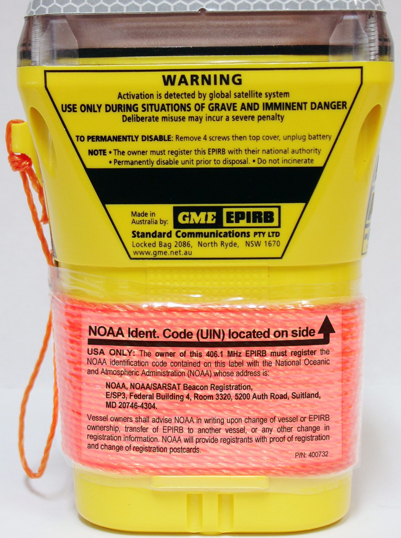
TXJMT401-FFMT401/401FF Class2 406MHz EPIRB
Standard Communications Pty Ltd
Click to zoom
Application Details
- Equipment Class
- GEP - 406 MHz EPIRB
- Date of Grant
- May 24, 2006
- Application Purpose
- Original Equipment
- Date of Application
- Feb 05, 2006
- Equipment Note
- MT401/401FF Class2 406MHz EPIRB
- Frequency Range
- 406.02800000 - 406.02800000
- Country
- Australia
Documents & Files
Document Text
Text extracted from the exhibit documents filed with the FCC. Open a document above to read the original.
Users Manual
INSTRUCTION MANUAL OWNER DETAILS Name: Address: Phone: Beacon UIN/15-HEX ID: Congratulations on purchasing your new MT400 series EPIRB. The GME MT400 and MT401 are the most advanced 406 MHz digital satellite beacons available today. Using new digital frequency generation technology, GME have developed and approved world wide, a new family of affordable high performance 406 MHz beacons. A CAUTIONARY NOTE: The satellite EPIRB is the most signifi cant advance in search and rescue technology in many years. It is not a substitute for a marine radio – mariners should not be over-reliant on any single system. Wise, safe mariners plan carefully, ensure that shore contacts know their sail plan, carry a marine radio and the right range of other safety equipment and operate their craft sensibly to suit conditions at sea. GENERAL DESCRIPTION The GME MT400 and MT401 digital Emergency Position Indicating Radio Beacons (EPIRB) are designed for use when the safety of your craft and crew is endangered and you have no other means of communication. The EPIRB can save your life and the lives of others on board by leading an air/sea rescue to your precise location. In the past, extensive and lengthy searches have been carried out for missing craft, sometimes to no avail. Your GME EPIRB is a self contained 406 MHz radio transmitter that emits an internationally-recognized distress signal on a frequency monitored by the COSPAS-SARSAT satellite system. The MT400 and MT401 contain a unique identity code which can be cross referenced to a database of registered 406 MHz beacons, allowing the beacon’s owner or vessel to be immediately identifi ed in the event of an emergency. Both models can be manually activated by the operator in an emergency situation. The MT401 will also automatically activate out of the mounting bracket if it is fl oated in water. Additionally each includes a ultra high performance solid state strobe and 121.5 MHz VHF homing beacon to assist in leading rescuers to your precise location. ABOUT THE COSPAS-SARSAT SYSTEM The COSPAS-SARSAT system is a complete global search and rescue service using geostationary and polar orbiting satellites. Many countries provide ground facilities known as Local User Terminals (LUTs). Polar orbiting satellites provide complete, although non-continuous, coverage of the earth (due to fact that these satellites can only view a portion of the earth at any given time) and can accurately resolve an active beacons’ location. Additionally, geostationary satellites can give an immediate alerting function in many regions of the world. The basic COSPAS-SARSAT concept is illustrated in the fi gure above. ABOUT 406 MHZ BEACONS 406 MHz beacons provide more accurate and reliable alert data to search and rescue agencies than the older 121.5/243 MHz systems presently being phased out. The older 121.5 MHz analogue system required that the satellite be within view of both the beacon and the LUT before it could transmit the beacons’ position. This limited the coverage to an area immediately surrounding the LUT. However, the digital nature of the 406 MHz system means that the satellites are able to store the beacons’ position and digital message, no matter where in the world it is received. These details are then relayed to the next LUT that comes into range, giving the 406 MHz system true global coverage. REGISTRATION AND TRANSFER OF OWNERSHIP Registration of your 406 MHz satellite EPIRB with the Registration Section of your National Authority is important because of the global alerting nature of the COSPAS-SARSAT system. Owner Registration Forms for registering your beacon may be supplied within the packaging, otherwise, your National Authority will be able to provide the correct forms. Up to date forms are often available online. The information provided in the registration is used only for search and rescue purposes. Promptly fi ll in the owner registration form upon completion of the sales transaction, then mail, fax or email it to your National Authority. If the beacon is to enter service immediately, complete the registration form and fax or email the information. Should the beacon be transferred to a new owner, as the previous owner you are to inform your National Authority by email, fax, letter or telephone of the name and address of the new owner. The new owner of the beacon is required to provide their National Authority with the information as shown on the registration form. This obligation transfers to all subsequent owners. NOTE: Your MT400/401 has been programmed with a unique identifying code which will be transmitted by the beacon in an emergency. Registering your beacon provides the authorities with immediate access to your details when the beacon is detected. This means they will know who you are, who your emergency contacts are and what type of vessel or craft you are in. In situations of accidental activation they can also immediately eliminate your beacon as an emergency situation by contacting you when activation is detected. PREVENTING ACCIDENTAL ACTIVATION The signal from an EPIRB is regarded by authorities as an indication of distress and is given an appropriate response. It is the responsibility of every owner of an EPIRB to ensure that it is not activated unintentionally or in situations that do not justify its use. Most cases of accidental transmission result from poor or inappropriate storage or failure to totally disable an old model EPIRB before disposal. The need to treat EPIRBs responsibly cannot be too highly emphasized. The MT400/401 will not commence transmitting until approximately 60 seconds after activation, providing a safety period of audible and visual warning. If you hear the beacon beeping while it is being carried or stowed, you may still be able to deactivate it during this time period without actually transmitting a distress signal. If in doubt, report the incident to your local authorities just in case. To minimize the possibility of a…
Text truncated - open the document above for the full version.
Cover Letter(s)
z Page 1 15 th February, 2006 Federal Communications Commision Office of Engineering and Technology Our Ref: ED060215-02 Your Ref: 30417 (EA939819 / TXJMT401/401FF) RE: Intended Application of FCC ID to Equipment To whom it may concern, In response to e-mail advice received from Ms Linda Elliott dated 15/02/2006 I have posted a new exhibit type ‘ID Label/Location Info’ for consideration as part of our application. This new file ( ‘MT401-401FF FCC_ID Placement(Version2).pdf’ ) nows show the complete FCC ID information and its intended location on the equipment. Further I wish to confirm that all outstanding filing fees have been payed in full (Remittance ID:874536, Authorisation Number R16735) Yours faithfully Craig Duncan Project Engineering Manager Standard Communications Pty Ltd
Cover Letter(s)
z Page 1 8 th March, 2006 Ms. Linda Elliott FCC Application Processing Branch Office of Engineering and Technology Federal Communications Commision Our Ref: ED060308-07 Your Ref: 30450 RE: Application of FCC ID to Equipment & Advice of Amended FCC ID Dear Linda, In response to e-mail advice we have taken corrective action and now forwarded a diagram (‘MT401-401FF FCC_ID Placement(Version3).pdf’ ) showing a valid character format FCC ID and its placement on our 406MHz EPIRB product Further please accept our advice that we wish to amend the previously requested ID which contained the illegal character ‘/’ to: FCC ID: TXJMT401-FF Yours faithfully Craig Duncan Project Engineering Manager Standard Communications Pty Ltd
External Photos
MT401 & MT401FF 406MHz EPIRB [External Photos for FCC Submission] Figure 1 - MT401 perspective 1 (front) Figure 2 - MT401 perspective 2 (rear) Figure 3 - MT401 front view Figure 4 - MT401 rear view Figure 5 - MT401 left view Figure 6 - MT401 - right view (existing) NOTE: Top left text frame to be modified to incorporate FCC ID information. Please refer to submission document relating to FCC ID marking. Figure 7 - MT401 in manual release bracket (No.1) Figure 8 - MT401 in manual release bracket (No.2) Figure 9 - MT401FF, complete (MT401 fitted in auto-release housing) NOTE: Black plastic adapter plate is fitted to the base of the MT401 when used in this configuration. Figure 10 - MT401FF Auto release housing (base) Figure 11 - MT401FF Auto-release housing, misc views
ID Label/Location Info
MT401/401FF 406MHz EPIRB Inclusion of FCC ID It is intended to include the FCC ID with other similar information on the left hand side of the beacon. It will either be laser engraved into the black to show text in relief as yellow (as shown), or printed as black text directly onto the yellow substrate. The content ‘XXXXXX’ will be amended to include the information as advised by the FCC. Approximate intended location
ID Label/Location Info
MT401/401FF 406MHz EPIRB Inclusion of FCC ID (Rev. 2) It is intended to include the FCC ID with other similar information on the left hand side of the beacon. It will either be laser engraved into the black to show text in relief as yellow (as shown), or printed as black text directly onto the yellow substrate. Figure 1 - Close View Figure 2 - Location on Equipment
ID Label/Location Info
MT401/401FF 406MHz EPIRB Inclusion of FCC ID (Rev. 3) It is intended to include the FCC ID with other similar information on the left hand side of the beacon. It will either be laser engraved into the black to show text in relief as yellow (as shown), or printed as black text directly onto the yellow substrate. Figure 1 - Close View Figure 2 - Location on Equipment
ID Label/Location Info
MT401/401FF 406MHz EPIRB Inclusion of FCC ID (Rev. 3) It is intended to include the FCC ID with other similar information on the left hand side of the beacon. It will either be laser engraved into the black to show text in relief as yellow (as shown), or printed as black text directly onto the yellow substrate. Figure 1 - Close View Figure 2 - Location on Equipment
ID Label/Location Info
z Page 1 8 th March, 2006 Ms. Linda Elliott FCC Application Processing Branch Office of Engineering and Technology Federal Communications Commision Our Ref: ED060308-07 Your Ref: 30450 RE: Application of FCC ID to Equipment & Advice of Amended FCC ID Dear Linda, In response to e-mail advice we have taken corrective action and now forwarded a diagram (‘MT401-401FF FCC_ID Placement(Version3).pdf’ ) showing a valid character format FCC ID and its placement on our 406MHz EPIRB product Further please accept our advice that we wish to amend the previously requested ID which contained the illegal character ‘/’ to: FCC ID: TXJMT401-FF Yours faithfully Craig Duncan Project Engineering Manager Standard Communications Pty Ltd
Internal Photos
MT401 & MT401FF 406MHz EPIRB [Internal Photos for FCC Submission] Figure 1 - Exploded assembly view Figure 2 - Cap assembly view (front & rear) Figure 3 - PCB, top view (panel of 4 in biscuit) Figure 4 - PCB bottom view (panel of 4 in biscuit) Figure 5 - Battery pack
Parts List/Tune Up Info
Document: 060118-03 Revision: 1 STANDARD COMMUNICATIONS PTY LTD Status: Released Engineering Department Issue Date: 18-01-2006 Commercial-in-Confidence ED060118- 03.Doc Page 1 of 8 MT400, MT401 & MT401FF 406MHz EPIRB Series Sub-Assembly Control & Bill of Material (BOM) This document is current as at 18 th January, 2006 1. PRODUCT DOCUMENTATION & SUB-ASSEMBLY CONTROL TABLE DESCRIPTION ECN OP PART NO DOCUMENT Product Level MT400 Series EPIRB/PLB - Configuration Coding 4669 -- -- 41776-3 MT400 Technical Description 4296 -- -- 41708-1 MT400 Block Diagram 4296 -- -- 41679-1 MT400 firmware Note1 -- -- OS0010 MT400 Series EPIRB, Technical Service Manual Create -- -- 42772-1 Component Level MT400 Circuit Diagram 4464 -- -- 10200-4 MT400 PCB (single) 4464 -- 580274 580274-3 MT400 PCB (panel of 4) 4464 -- 580274 580274-3x4 MT400 Top Overlay (SMD) 4464 SMD -- 42215-2 MT400 Circuit Specification by Reference 4605 SMD 97MT400PCB Rev 07 MT401 Circuit Specification by Reference Create SMD 97MT401PCB Rev 01 MT400 TopLoad Overlay 4464 MAY -- 42216-2 MT400 BottomLoad Overlay 4464 MAY -- 42217-2 MT400 Circuit Specification by Reference 4482 MAY 97MT400PCB Rev 03 MT401 Circuit Specification by Reference 4482 MAY 97MT401PCB Rev 02 Production - Assembly MT400 General Assembly 4470 -- config dependant 10201-5 MT400 Uncoded Chassis Assembly 4258 -- 97MT400COM 41950-2 MT401 Uncoded Chassis Assembly 4258 -- 97MT401COM 41950-2 MT400 Cover Reflector Assembly 4259 -- 97MT400RCR 41788-2 MT400 Battery Pack Assembly 4657 -- 97MT400BAT 41787-4 MT401 Chassis, Water Contact Assembly 4692 -- 97MT401RVT 42104-2 MT400 Chassis Winding Assembly 4692 -- 97MT400WND 41786-3 MT401 Chassis Winding Assembly 4692 -- 97MT401WND 41786-3 Mounting Bracket Collar Assy - MT401 Create -- 97MT401MTG 42208-1 FF Release Base - MT401/G Create -- 97BSE401FF 42864-1 Document: 060118-03 Revision: 1 STANDARD COMMUNICATIONS PTY LTD Status: Released Engineering Department Issue Date: 18-01-2006 Commercial-in-Confidence ED060118- 03.Doc Page 2 of 8 DESCRIPTION ECN OP PART NO DOCUMENT FF Release Cover - MT401/G Create -- 97CVR401FF 42865-1 Production - Test, General MT400 Test, Calibration and Information Management System 4296 -- -- 41858-1 ATE1 (BON) Test Set-up and Procedure 4482 BON -- 42174-2 ATE2 (CAL) Test Set-up and Procedure 4296 CAL -- 42175-1 ATE3 (LASER) Test Set-up and Procedure 4296 LSR -- 42176-1 ATE4 (FINAL) Test Set-up and Procedure 4534 TST -- 42177-2 ATE5 (FAULT) Test Set-up and Procedure 4296 -- -- 42178-1 LEAK-TEST Test Set-up and Procedure 4296 MAY -- 42179-1 Production - Test, Software ATE System Program Note 1 var -- TS0065 Production - Test, Station Scripts ATE1 (BON) Script for MT400 series Note 1 BON -- TS0066 ATE2 (CAL) Script for MT400 series Note 1 CAL -- TS0067 ATE3 (LASER) Script for MT400 series Note 1 LSR -- TS0068 ATE4 (FINAL) Script for MT400 series Note 1 TST -- TS0069 MT400 Series Model Definition Note 1 LSR -- ESMT400T NOTES: 1. Current Software Status must be obtained from latest revision of Software Master Register 40719 2. SCHEDULE OF PART USAGE BY MODEL Product No. Part Code Name / Description Quantity Usage MT400 MT400G MT401 MT401G MT401FF MT401FG 015773 MT401FFsvc Float Free housing service kit kit services 1 z z 015772 MT401con Float Free MT401 conversion kit kit services 1 z z 015771 MT400bat MT400 series battery service kit kit services 1 z z z z z z 015770 MT400extsw MT400 external switch service kit kit services 1 z z 015768 MT401extsw MT401 external switch refurbishment kit kit services 1 z z z z 015769 MT400intsw MT400/401internal switch refurbishment kit kit services 1 z z z z z z 015767 MT400ant MT400 series antenna service kit kit services 1 z z z z z z Document: 060118-03 Revision: 1 STANDARD COMMUNICATIONS PTY LTD Status: Released Engineering Department Issue Date: 18-01-2006 Commercial-in-Confidence ED060118- 03.Doc Page 3 of 8 Product No. Part Code Name / Description Quantity Usage MT400 MT400G MT401 MT401G MT401FF MT401FG 013358 61A0356 MT400 - mounting bracket collar 1 z z 014617 97MT401MTG MT401 - mounting bracket collar (c/w magnets for defeat mechanism) 1 z z 013357 61A0355 Mounting bracket common base 1 z z z z 015466 97CVR401FF Replacement Float Free Housing cover assembly (use with existing base) 1 z z 013365 97MT400PCB MT400 Electronic Circuit Module 1 z z 014125 97MT401PCB MT401 Electronic Circuit Module 1 z z z z --- MT400exPCB # MT400 Exchange Circuit Module services 1 z * --- MT400exPCB # MT401 Exchange Circuit Module services 1 z * z * 015766 MT401FFblt HRU bolt c/w SS nuts kit services 1 z z 002106 74A4G16PEM Screws - cap retention 1 z z z z z z 013654 74A6G25PEM Screws - battery retention 1 z z z z z z 014011 74A4G10CEM Screws - switch ext switch assy 1 z z z z z z 009768 74A2G10PEM Screws - leak test hole 1 z z z z z z 015173 61A0504 FF Adapter Plate (only) 1 z z 013366 97MT400WND MT400 lower chassis c/w lanyard 1 z z 014126 97MT401WND MT401 lower chassis c/w lanyard 1 z z z z 013333 280018 Lanyard Retention heat shrink tubing mult of 75mm z z z z z z 014289 61A0399 MT400/401 Cap (only) with reflective tape 1 z z z tba tba MT400G/401G Cap (only) with reflective tape 1 z z z 013337 400563 Security Label 1 z z z z z z 013739 46A0441 Ballast Weight 1 z z z z z z 014610 310221 Instruction manual 400/401 1 z z z z 015472 310337 Instruction manual 401FG/FGG 1 z z 014135 310209 Placard 400/401 1 z z z z 015442 310336 Placard 401FF/FG 1 z z NOTES: * Details to be advised. PCB Issue and firmware revision constraints apply. # These items not presently available, please contact Standard Communications Pty Ltd. Document: 060118-03 Revision: 1 STANDARD COMMUNICATIONS PTY LTD Status: Released Engineering Department Issue Date: 18-01-2006 Commercial-in-Confidence ED060118- 03.Doc Page 4 of 8 3. BILL OF MATERIALS- 97MT400PCB, 97MT401PCB Part Quantity Designator Description Footprint Number Used 013342, 013343, 013356 1 J4 ANTENNA MOUNTING BRACKET, CUSTOM MT400-Ant 14798 1 L15 inductor smd 080…
Text truncated - open the document above for the full version.
Test Report
ANNEX E CHANGE NOTICE FORM The Manufacturer of the Cospas-Sarsat Type Approved 406 MHz Distress Beacons: Manufacturer: _____ _____________________________________________ (name and address) _____ _____________________________________________ __________________________________________________ 406 MHz Beacon Model Numbers: _____ _____________________________________________ Cospas-Sarsat Type Approval Certificate Numbers: __________________________________________ Proposed New Model Numbers of Beacon: _________________________________________________ hereby informs Cospas-Sarsat of the following changes to production beacons planned date of change _______________ Oscillator type: _____ Battery: _____ (specify): ________________________________ Antenna type: _____ Homing transmitter: _____ Strobe light: _____ Size or shape of beacon package: _____ Significant change to circuit design: _____ Internal navigation device: _____ (specify): _________________________________ Other _____ (specify): _________________________________ and substantiates these changes with the attached technical documentation and beacon test results (if applicable). I hereby confirm that with these changes the above 406 MHz beacon models are technically equivalent to the type approved beacon and continue to meet the Cospas-Sarsat requirements. Dated: ........................................ Signed: .......................................................................... (for manufacturer) ANNEX J BEACON QUALITY ASSURANCE PLAN We, manufacturer of Cospas-Sarsat 406 MHz beacons (Manufacturer name and address) ___________________________________________ ___________________________________________ confirm that ALL PRODUCTION UNITS of the following beacon model(s), (model, part number) designed by us will be subjected to following tests at ambient temperature: - Digital message - Bit rate - Rise and fall times of the modulation waveform - Modulation Index (positive/negative) - Output power - Frequency stability (short, medium)* Note*: Beacon manufacturer shall provide technical data on the beacon frequency generation to demonstrate that the frequency stability tests at ambient temperature are sufficient for ensuring that each production beacon will exhibit frequency stability performance similar to the beacon submitted for type approval over the complete operating temperature range. If such assurance of adequate performance over the complete operating temperature range cannot be deduced from the technical data provided and the frequency stability test results at ambient temperature, a thermal gradient test shall be performed on all production units. - Other tests: _____________________________________________________________________ _____________________________________________________________________ _____________________________________________________________________ _____________________________________________________________________ _____________________________________________________________________ We confirm that the above tests will be performed as appropriate to ensure that the complete beacon satisfies Cospas-Sarsat requirements, as demonstrated by the test unit submitted for type approval. We agree to keep the test result sheet of every production beacon for inspection by Cospas- Sarsat, if required, for a minimum of 10 years. We confirm that Cospas-Sarsat representative(s) have the right to visit our premises to witness the production and testing process of the above-mentioned beacons. We understand that the cost related to the visit is to be borne by Cospas-Sarsat. We also accept that, upon official notification of Cospas-Sarsat, we may be required to re- submit a unit of the above beacon model selected by Cospas-Sarsat for the testing of parameters chosen at Cospas-Sarsat discretion at a Cospas-Sarsat accepted test facility selected by the Cospas-Sarsat. We understand that the cost of the testing shall be borne by Cospas-Sarsat. We understand that the Cospas-Sarsat Type Approval Certificate is subject to revocation should the beacon type for which it was issued, or its modifications, cease to meet the Cospas-Sarsat specifications, or Cospas-Sarsat has determined that this quality assurance plan is not implemented in a satisfactory manner. Date Name, Position and Signature of beacon Manufacturer Representative MT401FF Coding & Sample Messages Page 1 of 6 PROTOCOL: SERIAL USER A) PROGRAMMING SOFTWARE UNIT INFORMATION Date & Time: 19/09/2005 11:33:11 AM Model: EPIRB MT401 (C/S Class2 Water Activation) S/N (Year + Month + Serial): YMM07163 Firmware Version: OS0010.4.04 PCB Version: 3 Transmission Frequency: 406.028 MHz MESSAGE INFORMATION Message Format[25]: 0 (Short) Protocol Flag[26]: 1 Country Code[27-36]: 503 (Australia) User Protocol Type[37-39]: 3 (Serial user protocol) Beacon Type[40-42]: 2 (Float free EPIRB with serial number) TAC Flag[43]: 0 User Defined Serial Number[44-63]: 7163 National Use Field 1[64-73]: Not used, all 0s National Use Field 2[74-83]: Not used, all 0s Auxiliary Radio-Locating Device[84-85]: 1 (121.5 MHz) Activation Mode[108]: 1 (Auto And Manual) 15-HEX ID/UIN[26-85]: BEED006FEC00001 Full Message[25-112]: 5F768037F600000E9B6490 B) COSPAS/SARSAT WEB BASED DECODE SOFTWARE MT401FF Coding & Sample Messages Page 2 of 6 C) ACTUAL DECODE OF PROGRAMMED BEACON SELF TEST **** SARTECH ARG5410 BEACON TESTER **** ***** 12:43:47 19 Sep 2005 **** MESSAGE No.23 RECEIVED AT: 11:35:09 19 Sep 2005 FRAMING/STATUS: S'TEST OK FREQUENCY: 406.0285 MHz PASS COUNTRY: 503 AUSTRAL 30 HEX ID: 5F768037F600000E9B649000000000 15 HEX ID: BEED006FEC00001 PROTOCOL: SERIALISED BEACON TYPE: EPIRB AUTOMATIC IDENTITY: #7163 HOMING: 121.5MHz OTHER INFO: 406MHz Power 262 121.5MHz Power 30 NORMAL **** SARTECH ARG5410 BEACON TESTER **** ***** 12:44:17 19 Sep 2005 **** MESSAGE No.24 RECEIVED AT: 11:36:19 19 Sep 2005 FRAMING/STATUS: NORMAL OK FREQUENCY: 406.0286 MHz PASS COUNTRY: 503 AUSTRAL 30 HEX ID: 5F768037F600000E9B6490000…
Text truncated - open the document above for the full version.
Test Report
STANDARD COMMUNICATIONS PTY LTD Document: 041115-01 Engineering DepartmentRevision: 1 Status: Release Commercial-in-Confidence Issue Date:15-11-2004 TEST REPORT ON THE MT400/401 PREPARED FOR COSPAS/SARSAT Prepared: Craig DUNCAN Position: Project Engineering Manager Date: 19 th October, 2004 Endorsement: 1. BACKGROUND AND PURPOSE The MT400, Class 2 Manually Activated 406MHz EPIRB fitted with strobe and homing transmitter has been issued with TAC139 by COSPAS/SARSAT. Water Activated Product Variant 1.1 1.2 In a proposed future configuration, the current manual activation circuitry will be supplemented with a water sensor switch. The additional componentry required to implement this function is minimal and separate from that of the existing design. As such it can be considered as a very minor modification to the current product. The fitting of the water sensor is optional within the design. Models with the circuitry fitted will be uniquely distinguished by the Model number MT401 and a yellow chassis colour. Manually activated units will continue to be predominantly orange and identified as a MT400. So as to avoid the likely levels of false alerts generated by water activated EPIRB being transported out of their mounting brackets, some National Administrations have indicate a strong preference for the continued availability of Manual only type beacons into the growing 406 recreational market. For this reason Standard Communications proposes to produce the MT400 in its base form, and also as the MT401 water activated version. Improved Energy Efficiency and Associated Battery Life Improvements in tuning of the 121.5MHz homing transmitter RF power amplifier have realised considerable gains in operating efficiency. Without change to the homing signals output level, or other characteristics the battery power consumption has decreased when compared to the original MT400 test model. This excess energy capacity now allows the MT400/401 beacon to be rated with a greater battery change interval than in the past. Commercial-in-Confidence Page 1 of 3 STANDARD COMMUNICATIONS PTY LTD Document: 041115-01 Engineering DepartmentRevision: 1 Status: Release Commercial-in-Confidence Issue Date:15-11-2004 2.DATA AND SUPPORTING INFORMATION UUT2.1 2.2 2.2.1 2.2.2 2.3 All tests within this report were carried out on a single MT401 beacon, S/N 157. This unit was randomly selected from a pilot run of 16 units and has not been specially prepared in any way for the purposes of this report. S/N157 was built to normal production standards and assembled using normal production processes within Standard Communications’ manufacturing facility at North Ryde NSW, Australia. The MT400, and water activated variant MT401, share common production fixtures and Automated Test Facilities (ATE). Test Requirements Water Activation In reference to prior correspondence with COSPAS/SARSAT’s Sergey Mikhailov (27/11/2003), and Wayne Carney( 13/7/2004) the following manufacturer’s test have been carried out and included within this report: y7. 406MHz VSWR Check, y10. Operating Lifetime at Minimum Temperature, and y11. Temperature Gradient. Furthermore the following test information is also provided: y2. Digital Message, and y16. Beacon Coding Software. Battery Life The application for extension of rated battery life is supported by the following: yED041012-06 Rev 1 MT400/401 Qualification Testing, Low Temperature Operating Life - Battery Preconditioning (& Annexes), and y10. Operating Lifetime at Minimum Temperature (in common with re-testing for Water Activation). Testing All testing has been carried out by appropriately qualified and experienced Professionals. Commercial-in-Confidence Page 2 of 3 STANDARD COMMUNICATIONS PTY LTD Document: 041115-01 Engineering Department Revision: 1 Status: Release Commercial-in-Confidence Issue Date: 15-11-2004 Commercial-in-Confidence Page 3 of 3 2.4Test Equipment The following commercially available major test equipment items were used to support the measurements carried out for this report. ItemDescription ManufacturerModelS/N 1High Resolution Programmable Timer/Counter Analyser FlukePM6681786931 2Rubidium Frequency Standard Stanford Research Systems FS72565238 39kHz - 1.2GHz Signal Generator Marconi Inst. 2023112240/015 4406MHz Beacon Tester ARG/SARTECH ARG5410 MkII 058 51 Gs/s Digital Storage Oscilloscope TektronixTDS2014C031958 6.9kHz...3GHz Spectrum Analyser Rohde & Schwarz 1093.4495.03100303 2.5Other Information The following information is also provided: yPicture of the MT401, yChassis artwork unique to MT401 model (all other as per MT400), and yElectronic copy of Instruction Manual. 3. CONCLUSION Frequency stability and other performance requirements, including data modulation, are unaffected by the inclusion of water activation circuitry. Sample messages have been provided to illustrate the correct operation of beacon coding software when used with a MT401. Furthermore, energy efficiency improvements, through improved factory tuning of the 121.5MHz homer transmitter, now support the increase in stated battery life of the MT400/401 from 5 years to 7.5 years. This is achieved whilst simultaneously also realising an increase in reserve (excess) capacity at the end of the extended shelf life. GME MT401 - 406 MHz BEACON TEST RESULTS PARAMETERS TO BE MEASURED DURING TESTS RANGE OF SPECIFICATION UNITS TEST RESULTS CO MMENTS T min. ( -20 ° C) T amb. ( +22.5 ° C) T max. ( +55 ° C) 1. POWER OUTPUT • transmitter power output • power output rise time • power output 1 ms before burst 35 - 39 <5 must be < -10 dBm dBmms √ * 2. DIGITAL MESSAGE Bits number • bit sync 1-15 • frame sync 16-24 • format flag 25 • protocol flag 26 • identification/position data 27-85 • BCH code 86-106 • emerg. code/nat. use/s upplem. data 107-112 • additional data/BCH (if applicable) 113-144 • position error (if applicable) 15 bits "1"9 bits (000101111)1 bit1 bit59 bits21 bits6 bits32 bits < 5 √√ data bit data bit √√ data bits √ km …
Text truncated - open the document above for the full version.
Test Report
Click For a Printer Friendly Version Organization Name: Intespace Address: 18 Avenue Edouard Belin BP 4356 31029 Toulouse Cedex 4 , France Telephone Number: +33 561 28 1111 Fax Number: +33 561 28 1122 E-mail: Name: MM. A. Serdane 161.011 Comments: Qualified to conduct RTCM Appendix A tests for USCG and RTCM Appendix B tests for COSPAS/SARSAT Marine Safety Center Office of Design and Engineering Standards Page 1 of 1USCG Approved Equipment Listing 10/01/2006http://cgmix.uscg.mil/EQLabs/Search/OrganizationDetails.aspx?LabID=22&SubPart=161....
Contact Information
Applicant
Filip Zalio(General Manager - Engineering)
Technical Contact
Standard Communications Pty LtdCraig John Duncan
[email protected]61298446666
Project Engineering Manager · Northe Ryde, NSW · Australia
Non-Technical Contact
Standard Communications PtySean Griffin
[email protected]61298446666
Technical Specifications
| # | Rule Parts | Frequency Range | Power Output | Emission | Tolerance |
|---|---|---|---|---|---|
| 1 | 80.1101(c)(5) | 406.028 MHz - 406.028 MHz | 5 W | 16K0G1D | 1000.0000000000 Hz |
Other Applications from Standard Communications Pty Ltd
TXJ-XRS660U
Jul 29, 2026XRS Connect Handheld UHF GMRS Radio
Equipment Class
TNF - Licensed Non-Broadcast Transmitter Held to Face
TXJ-GX510
Dec 10, 2025GMDSS Handheld VHF Radio
Equipment Class
TNF - Licensed Non-Broadcast Transmitter Held to Face
TXJGX400
Dec 28, 2014HF CB TRANSCEIVER
Equipment Class
TNB - Licensed Non-Broadcast Station Transmitter
TXJCM1039U
Apr 30, 2013RADIO TRANSCEIVER
Equipment Class
TNB - Licensed Non-Broadcast Station Transmitter
TXJMT403-G
Apr 16, 2008MT403/403G/403FF/403FG Class2 406MHz EPIRB
Equipment Class
GEP - 406 MHz EPIRB