TXRFPT0714Wireless Grill Thermometer
Yangzhou Fupond Electronic Technology Corp., Ltd.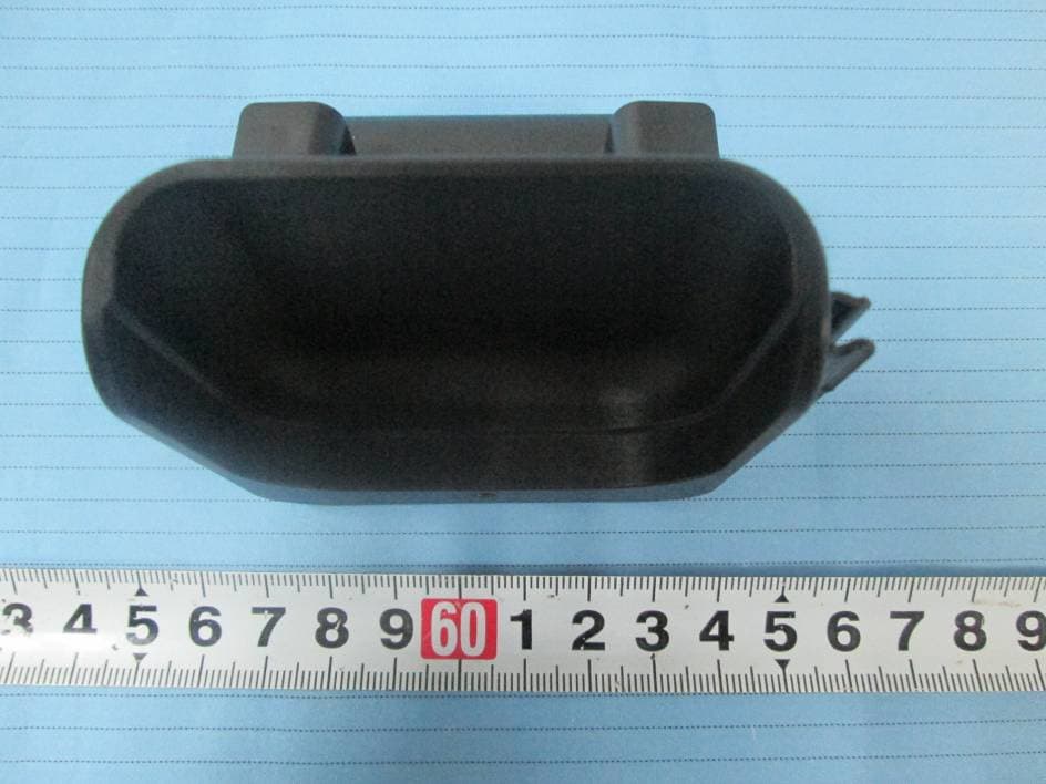
Click to zoom
Application Details
- Equipment Class
- DSC - Part 15 Security/Remote Control Transmitter
- Date of Grant
- Aug 28, 2014
- Application Purpose
- Original Equipment
- Date of Application
- Aug 28, 2014
- Equipment Note
- Wireless Grill Thermometer
- Frequency Range
- 433.92000000 - 433.92000000
- Country
- China
Documents & Files
Document Text
Text extracted from the exhibit documents filed with the FCC. Open a document above to read the original.
Users Manual
USER MANUAL LED INDICATOR LIGHT The indicator light in the center of the transmitter base flashes BLUE to indicate that a temperature reading is being transmitted. FEATURES: WIRELESS GRILL THERMOMETER Wireless Thermometer Backlit LCD Screen Transmitter Base Stainless Steel Meat Probe Heat Resistant Probe Wire Probe Holder Pocket Clip Audible Alarm Cooking Timer Wireless Thermometer Transmitter Base Heat Resistant Probe Wire Stainless Steel Meat Probe Probe Connector Plug Probe Socket OPERATING INSTRUCTIONS: 1. CONNECTING THE PROBE Locate the probe socket on the right side of the transmitter base. Insert the probe connector-plug into the socket (1A). 2. PROBE INSERTION Insert probe tip into the center of the thickest part of the meat, taking care not to pierce through it (2A). Do not expose any part of the probe to open flames. 3. POWERING ON Locate the power switch on the bottom of the trans- mitter base (3A). Move switch to the ON position. A LED indicator light will flash BLUE to indicate a signal is being transmitted. Locate the power switch on the side of the wireless thermometer. Move switch to the ON position (3B). Connection will establish automatically. Turn OFF power to transmitter base and wireless thermometer when not in use. BATTERY INSTALLATION WIRELESS THERMOMETER 1. Remove the battery cover on the back of the wireless thermometer. 2. Insert 2 AAA 1.5V batteries as indicated by the polarity symbols (+and-). Replace the battery cover. TRANSMITTER BASE 1. Remove the battery cover on the bottom of the transmitter base. 2. Insert 2 AAA 1.5V batteries as indicated by the polarity symbols (+and-). Replace the battery cover. 4. SELECT MEAT TYPE Press “MEAT” button to navigate and select the desired meat types (4A). Each press will change the display in the following sequence (4B): 5. SELECT TASTE LEVEL Press “TASTE” button to select the doneness level Rare, Medium Rare, Medium, Medium Well or Well Done (5A). The target temperature appears on the LCD screen. Begin cooking. The cooking alerts will sound when the meat has reached the target temperature. Hamburger, Turkey, Chicken, and Fish have only doneness level of Well. 2 1 3B 3A 5A 4A 6. MANUALLY SET TARGET TEMPERATURE Press and hold down “MODE” button for 5 seconds to manually set the temperature (6A). Press “MIN ” and/or “SEC ” button(s) to select your desired temperature. Press “MODE” button to confirm your setting. Your target temperature will appear on the LCD screen. Begin cooking. The cooking alerts will sound when the meat has reached the target temperature. 4B PORK TURKEYCHICKEN FISHBEEF LAMB VEAL HAMBURGER Wireless Grill Thermometer is NOT weather resistant. Store indoors. CAUTION: Stainless steel meat probe and probe wire will become extremely hot during use. Remove probe from meat using an oven mitt and allow to cool. Remove probe prior to slicing into meat. SAFETY INFORMATION Please read and understand this entire manual before attempting to assemble, operate or install the product. If you have any questions regarding the product, please call customer service at 1-800-254-0111. 7. °C/°F TEMPERATURE DISPLAY Locate °C/°F switch on the back of the Wireless Thermometer. Slide switch to select Fahrenheit or Celsius temperature scale. 8. BACKLIGHT Press any button while powered ON to illuminate the backlight. 9. COUNT-UP/COUNT-DOWN TIMER Press “MODE” to select timer function. To set a count-down time, press “MIN” and/or “SEC” button(s). Press “START” button to start count-down. If no count-down time is set, press “START” button to count-up. To clear timer, press “STOP” button to pause count-down or count-up. Once paused, press “MIN” and “SEC” buttons at the same time to reset to zero. Once a count-down has finished, the unit will beep. To silence the alert press any button. TROUBLESHOOTING NOTE: The timer will count up to or down from 99:59. PROBLEM Current temperature does not appear on LCD upon powering ON. POSSIBLE CAUSE Interference CORRECTIVE ACTION Place wireless thermometer close to transmitter base. Turn both units ON and OFF until a connection is established. If problem persists check batteries. PROBLEM Current temperature does not appear on LCD during use. POSSIBLE CAUSE Out of range CORRECTIVE ACTION Move wireless transmitter close to transmitter base to reestablish a connection. If a connection does not establish automatically, turn both units ON and OFF until a connection is established. PROBLEM Meat over/under cooked PROBLEM "H” is displayed instead of current temperature. POSSIBLE CAUSE Probe not centered in the thickest part of meat. POSSIBLE CAUSE Probe temperature sensor has exceeded 299°F. CORRECTIVE ACTION For best results, make certain the probe is positioned properly. CORRECTIVE ACTION Remove probe from heat immediately and allow to cool. Turn transmitter base off and unplug the probe wire. Reconnect probe and test by powering on and establishing a connection. If the LCD still displays “H" then the probe sensor has been damaged. Please call customer service to replace. CARE AND MAINTENANCE Unplug stainless steel meat probe from transmitter base. Hand wash stainless steel meat probe ONLY using mild soap and hot water. Rinse thoroughly. Dry completely with a soft cloth. Transmitter requires 2 “AAA” 1.5V batteries (not included). Wireless receiver requires 2 “AAA” 1.5V batteries (not included). 1A WARNING: The meat probe is designed to measure internal meat temperature and has an operational range between 32°F and 299°F (0°C and 148°C). Exposing the probe tip to temperatures above 299°F could cause damage to the temperature sensor. WARNING: DO NOT mix old and new batteries. DO NOT mix alkaline, standard (carbon-zinc) or rechargeable (nickel-cadmium) batteries. DO NOT dispose of batteries in fire. Batteries may explode or leak. Please dispose of batteries properly. Remove the batteries when not in use for an extended period of time. Batteries could leak causing corrosion. 2A Probe Holder MEAT BUTTON 6A MO…
Text truncated - open the document above for the full version.
Block Diagram
1 2 3 4 AB C D 4 3 2 1 D C B A Title N umber Revision Size POWER SWITCH 3V BATTERY MODULATO R & AMPLIFIE R MCU ANTENNA N TC TEMPERATURE SENSO R 433MHzCRYSTAL
External Photos
EXHIBIT B - EUT EXTERNAL PHOTOGRAPHS EUT – Front View EUT – Rear View EUT – Top View EUT – Bottom View EUT – Left View EUT – Right View
ID Label/Location Info
EXHIBIT A - FCC ID LABELING AND LOCATION FCC ID Label Proposed FCC ID Label Location The label shown shall be permanently affixed at a conspicuous location on the device and be readily visible to the user at the time purchase (Labeling requirements per 2.925) Label here
Internal Photos
EXHIBIT C - EUT INTERNAL PHOTOGRAPHS EUT - Battery off View EUT - Cover off View EUT - Main Board Top View EUT - Main Board Bottom View Antenna
Operational Description
CIRCUIT DESCRIPTION OF TX The MCU can get the actual temperature by measuring the NTC temperature sensor’s resistence. Then the result can be modulated at 433.92 MHz and the signal will be sent by the antenna. CIRCUIT DESCRIPTION OF RX The 433.92 MHz signal can be demodulated and the MCU will identify the correct data. The final result will be displayed on the LCD screen.
Schematics
1 2 3 4 A B C D 4 3 2 1 D C B A Title Revision :4 C2100nF C30.1uF C110nF R1100K C520pFC620pF Y132768Hz COM1 20 COM2 19 COM3 18 COM4 17 SEG1 16 SEG2 15 SEG3 14 SEG4 13 SEG5 12 SEG6 11 SEG7 10 SEG8 9 SEG9 8 SEG10 7 SEG11 6 SEG12 5 SEG13 4 SEG14 3 SEG15 2 SEG16 1 SEG17/P7.0 64 SEG18/P7.1 63 SEG19/P7.2 62 SEG20/P7.3 61 SEG21/P7.4 60 SEG22/P7.5 59 SEG23/P7.6 58 SEG24/P7.7 57 SEG25/P8.0 56 SEG26/P8.1 55 SEG27/P8.2 54 SEG28/P8.3 53 SEG29/P8.4 52 SEG30/P8.5 51 SEG31/P8.6 50 SEG32/P8.7 46 N C 47 N C 48 N C 49 VB 21 VA 22 VLCD2 23 VLCD3 24 /RESET 25 GND 26 R_OSCI 27 OSCO 28 VDD 29 XI 30 XOUT 31 P5.4/INT0 32 P5.5/INT1 33 P5.6/TCC 34 N C 35 N C 36 P5.7/IROUT 37 P6.0 38 P61 39 P62 40 P63 41 P64 42 P65 43 P66 44 P67 45 U1EM78P468 12 J1 POWE R VDD C4 1uF R2100KNTC R310K 1% R533K VDD R810K VDD C7100nF L133nH L233nH Q1R25Q38050 Q28050 C85pF R710K C95pF VDD 1 2 3 J5CON3 P54P55P56 R410 R610 J4 433MHz RF RF E1ANTENNA
Test Report
Note: This test report is prepared for the customer shown above and for the equipment described herein. It may not be duplicated or used in part without prior written consent from Bay Area Compliance Laboratories Corp. FCC PART 15.231 TEST REPORT For Yangzhou Fupond Electronic Technology Co., Ltd. Hangji Industrial Park, Yangzhou, Jiangsu Province, China FCC ID: TXRFPT0714 Report Type: Original Report Product Type: Wireless Grill Thermometer Test Engineer: August He Report Number: RSZ140701001-00 Report Date: 2014-07-28 Reviewed By: Jimmy Xiao RF Engineer Prepared By: Bay Area Compliance Laboratories Corp. (Shenzhen) 6/F, the 3rd Phase of WanLi Industrial Building, ShiHua Road, FuTian Free Trade Zone Shenzhen, Guangdong, China Tel: +86-755-33320018 Fax: +86-755-33320008 www.baclcorp.com.cn Bay Area Compliance Laboratories Corp. (Shenzhen) Report No.: RSZ140701001-00 FCC Part 15.231 Page 2 of 18 TABLE OF CONTENTS GENERAL INFORMATION ....................................................................................................................................... 3 PRODUCT DESCRIPTION FOR EQUIPMENT UNDER TEST (EUT) ..................................................................................... 3 OBJECTIVE ................................................................................................................................................................... 3 RELATED SUBMITTAL(S)/GRANT(S) ............................................................................................................................. 3 TEST METHODOLOGY .................................................................................................................................................. 3 TEST FACILITY ............................................................................................................................................................. 3 SYSTEM TEST CONFIGURATION .......................................................................................................................... 4 JUSTIFICATION ............................................................................................................................................................. 4 SPECIAL ACCESSORIES ................................................................................................................................................. 4 EQUIPMENT MODIFICATIONS ....................................................................................................................................... 4 BLOCK DIAGRAM OF TEST SETUP ................................................................................................................................ 4 SUMMARY OF TEST RESULTS ............................................................................................................................... 5 FCC §15.203 - ANTENNA REQUIREMENT ............................................................................................................. 6 APPLICABLE STANDARD .............................................................................................................................................. 6 ANTENNA CONNECTOR CONSTRUCTION ...................................................................................................................... 6 FCC §15.205, §15.209, §15.231 (E) - RADIATED EMISSIONS ............................................................................... 7 APPLICABLE STANDARD .............................................................................................................................................. 7 MEASUREMENT UNCERTAINTY .................................................................................................................................... 7 EUT SETUP .................................................................................................................................................................. 8 EMI TEST RECEIVER SETUP ......................................................................................................................................... 8 TEST PROCEDURE ........................................................................................................................................................ 9 TEST EQUIPMENT LIST AND DETAILS ........................................................................................................................... 9 CORRECTED AMPLITUDE & MARGIN CALCULATION ................................................................................................... 9 TEST RESULTS SUMMARY ............................................................................................................................................ 9 TEST DATA ................................................................................................................................................................ 10 FCC §15.231(C) – 20 DB EMISSION BANDWIDTH TESTING ........................................................................... 14 APPLICABLE STANDARD ............................................................................................................................................ 14 TEST PROCEDURE ...................................................................................................................................................... 14 TEST EQUIPMENT LIST AND DETAILS ......................................................................................................................... 14 TEST DATA ................................................................................................................................................................ 14 FCC §15.231(E) – TRANSMISSION AND SILENT PERIOD TESTING ............................................................. 16 APPLICABLE STANDARD .................................................................................................................................…
Text truncated - open the document above for the full version.
Test Setup Photos
EXHIBIT D - TEST SETUP PHOTOGRAPHS Radiated Emission View (Below 1 GHz) Radiated Emission View (Above 1 GHz)
Contact Information
Applicant
Robert Wong(manager)
Test Firm
Bay Area Compliance Laboratory Corp. (Shenzhen)John Chan
Technical Specifications
| # | Rule Parts | Frequency Range | Power Output |
|---|---|---|---|
| 1 | 15.231(e) | 433.92 MHz - 433.92 MHz | - |
Other Applications from Yangzhou Fupond Electronic Technology Corp., Ltd.
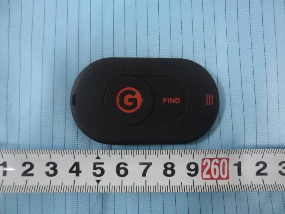
TXRFPT0614
Jul 07, 2014Wireless Key Finder
Equipment Class
DSC - Part 15 Security/Remote Control Transmitter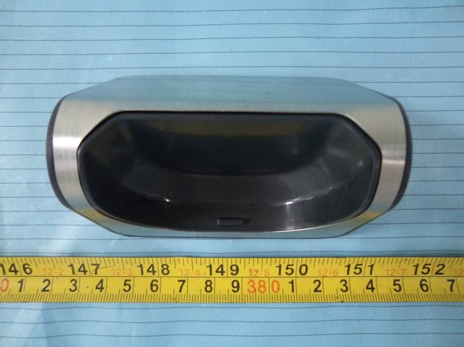
TXRFPT1305
Oct 23, 2013Remote Grill Thermometer (Transmitter)
Equipment Class
DSC - Part 15 Security/Remote Control Transmitter
TXRFKF-1006
Aug 21, 2010Remote Key Finder
Equipment Class
DSC - Part 15 Security/Remote Control Transmitter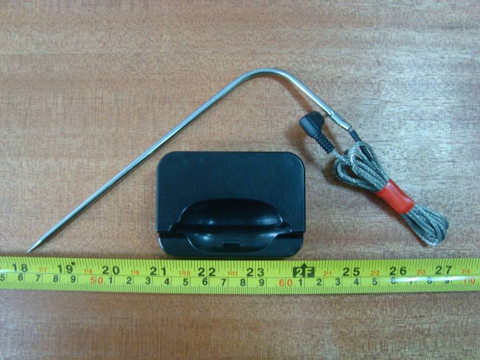
TXRFPT0912
Jan 04, 2010Remote Grill Thermometer
Equipment Class
DSC - Part 15 Security/Remote Control Transmitter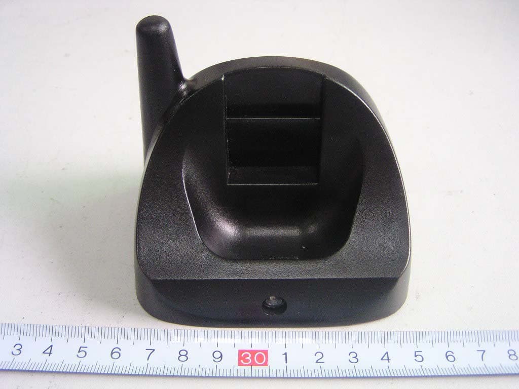
TXRFPT0601
Apr 02, 2006Remote Grill Thermometer
Equipment Class
DSR - Part 15 Remote Control/Security Device Transceiver