TXRFPT1305Remote Grill Thermometer (Transmitter)
Yangzhou Fupond Electronic Technology Corp., Ltd.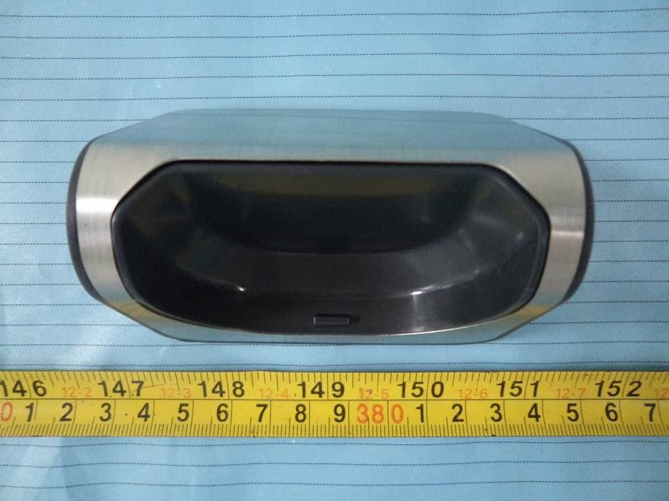
Click to zoom
Application Details
- Equipment Class
- DSC - Part 15 Security/Remote Control Transmitter
- Date of Grant
- Oct 23, 2013
- Application Purpose
- Original Equipment
- Date of Application
- Oct 23, 2013
- Equipment Note
- Remote Grill Thermometer (Transmitter)
- Frequency Range
- 433.92000000 - 433.92000000
- Country
- China
Documents & Files
Document Text
Text extracted from the exhibit documents filed with the FCC. Open a document above to read the original.
Users Manual
ITEM/ARTICLE/ARTÍCULO #0507287 MODEL/MODÈLE/MODELO #SBQ-5760-CU WIRELESS THERMOMETER THERMOMÈTRE SANS FIL TERMÓMETRO INALÁMBRICO WIRELESS THERMOMETER THERMOMÈTRE SANS FIL TERMÓMETRO INALÁMBRICO TRANSMITTER BASE BASE À ÉMETTEUR BASE DEL TRANSMISOR BELT CLIP PINCE À CEINTURE SUJETADOR PARA CINTURÓN PROBE CONNECTOR PLUG CONNECTEUR DE SONDE ENCHUFE CONECTOR DEL MEDIDOR MEAT PROBE SONDE THERMIQUE MEDIDOR PARA CARNE PROBE WIRE FIL DE SONDE CONDUCTOR DEL MEDIDOR PROBE PORT PRISE DE SONDE PUERTO DEL MEDIDOR Current temperature does not appear on LCD upon powering ON. La température ne s’affiche pas à l’écran ACL lorsque l’appareil est mis en marche. La temperatura actual no aparece en la pantalla LCD al encender la unidad. Current temperature does not appear on LCD during use. La température ne s’affiche pas à l’écran ACL lors de l’utilisation. La temperatura actual no aparece en la pantalla durante el uso. POSSIBLE CAUSE CAUSE POSSIBLE CAUSA POSIBLE CORRECTIVE ACTION MESURE CORRECTIVE ACCIÓN CORRECTIVA Interference L’appareil subit des interférences. Interferencia. Out of range. Le thermomètre est hors du rayon d’action de la base à émetteur. Fuera de rango. Place wireless thermometer close to transmitter base. Turn both units ON and OFF until a connection is established. If problem persists, check batteries. Rapprochez le thermomètre sans fil de la base à émetteur. Allumez et éteignez les deux appareils jusqu’à ce qu’une connexion soit établie. Si le problème persiste, vérifiez les piles. Coloque el termómetro inalámbrico cerca de la base del transmisor. Encienda y apague ambas unidades hasta que se establezca una conexión. Si el problema persiste, revise las baterías. Move wireless thermometer close to transmitter base to reestablish a connection. If a connection does not establish automatically, turn both units ON and Off until a connection is established. If problem persists, check batteries. Rapprochez le thermomètre sans fil de la base à émetteur pour rétablir la connexion. Si la connexion ne s’établit pas automatiquement, allumez et éteignez les deux appareils jusqu’à ce qu’elle s’établisse. Si le problème persiste, vérifiez les piles. Coloque el termómetro inalámbrico cerca de la base del transmisor para restablecer la conexión. Si no se establece la conexión automáticamente, encienda y apague ambas conexiones hasta que se establezca la conexión. Si el problema persiste, revise las baterías. . Meat over/under cooked. Les viandes sont insuffisamment ou excessivement cuites. Carne demasiado/poco cocida. Probe not centered in the thickest part of meat. La sonde n’est pas centrée dans la partie la plus épaisse des viandes. El medidor no está centrado en la parte más gruesa de la carne. For best results, make certain the probe is positioned properly. Pour obtenir des résultats optimaux, assurez-vous de placer la sonde correctement. Para obtener mejores resultados, asegúrese de que el medidor está ubicado de forma correcta. BACK COVER 9. COUNT-UP/COUNT-DOWN TIMER MINUTERIE À COMPTE POSITIF/À REBOURS TEMPORIZADOR DE CUENTA PROGRESIVA/REGRESIVA Remove the battery cover on the back of the wireless thermometer. Locate the Fahrenheit or Celsius temperature scale switch below the battery compartment. Move switch to the desired temperature scale. Retirez le couvercle du compartiment à piles situé à l’arrière du thermomètre sans fil. Repérez l’interrupteur d’affichage de la température en degrés Celsius ou Fahrenheit situé sous le compartiment à piles. Réglez l’interrupteur à l’unité désirée. Retire la cubierta de las baterías en la parte posterior del termómetro inalámbrico. Busque el interruptor de escala de temperatura en Fahrenheit o Celsius debajo del compartimiento de las baterías. Coloque el interruptor en la escala de temperatura deseada. 7. °C/°F TEMPERATURE DISPLAY /AFFICHAGE DE LA TEMPÉRATURE EN DEGRÉS CELSIUS/FAHRENHEIT /PANTALLA DE TEMPERATURA EN °C/°F PROBLEM PROBLÈME PROBLEMA Tenez enfoncé le bouton « MODE » pendant 3 secondes pour régler la température manuellement. Appuyez sur les boutons MIN et SEC pour sélectionner la température désirée. Appuyez sur le bouton MODE pour confirmer la sélection. La température ciblée apparaîtra à l’écran ACL. Commencez la cuisson. Des signaux sonores se feront entendre et l’écran ACL deviendra rouge et clignotera lorsque la viande atteindra la température ciblée. Mantenga presionado el botón "MODE” (Modo) durante 3 segundos para fijar manualmente la temperatura. Presione los botones “MIN” (Minuto) o “SEC” (Segundo) para seleccionar la temperatura deseada. Presione el botón "MODE” para confirmar el ajuste. La temperatura objetivo aparecerá en la pantalla LCD. Empiece con la cocción. Las alarmas de cocción sonarán y la pantalla LCD destellará una luz roja cuando la carne alcance la temperatura objetivo. Press “MODE” button to switch from thermometer to timer. To set a count-down time, press “MIN” and/or “SEC” button(s). Press “TASTE/START” button to start count-down. If no count-down time is set, press “TASTE/START” to count-up. To clear timer, press “MEAT/STOP” to pause count-down or count-up. Once paused, press “MIN” and “SEC” button at the same time to reset to zero. Once a countdown has finished, the unit will beep. To silence the alert press any button. NOTE: The timer will count up to or down from 99:59. Press “MODE” again to switch back to thermometer. Appuyez sur le bouton MODE pour passer du mode thermomètre au mode minuterie. Pour régler un compte à rebours, appuyez sur les boutons MIN ou SEC. Appuyez sur le bouton TASTE/START (cuisson/démarrer) pour lancer le compte à rebours. Si aucun compte à rebours n’est réglé, appuyez sur le bouton TASTE/START (cuisson/démarrer) pour lancer un compte positif. Pour ramener la minuterie à zéro, appuyez d’abord sur le bouton MEAT/STOP (viande/arrêter) pour interrompre le compte à rebours ou le compte positif. Une fois le compte interrompu, appuyez sur les boutons MIN et SEC en même temps pour remettre la m…
Text truncated - open the document above for the full version.
External Photos
EXHIBIT B - EUT EXTERNAL PHOTOGRAPHS EUT – All View EUT – Top View EUT – Bottom View EUT – Front View EUT – Rear View EUT – Left Side View EUT – Right Side View
ID Label/Location Info
EXHIBIT A - FCC ID LABELING AND LOCATION FCC ID Label FCC ID Label Location The label shown shall be permanently affixed at a conspicuous location on the device and be readily visible to the user at the time purchase (Labeling requirements per 2.925) Label here
Internal Photos
EXHIBIT C - EUT INTERNAL PHOTOGRAPHS EUT – Battery off View EUT – Cover off View EUT – Main Board Top View EUT – Main Board Bottom View Antenna
Test Report
Note: This test report is prepared for the customer shown above and for the equipment described herein. It may not be duplicated or used in part without prior written consent from Bay Area Compliance Laboratories Corp. FCC PART 15.231 TEST REPORT For Yangzhou Fupond Electronic Technology Corp., Ltd. HangJi Industrial Park, Yangzhou, Jiangsu Province, China FCC ID: TXRFPT1305 Report Type: Original Report Product Type: Remote Grill Thermometer (Transmitter) Test Engineer: Gardon Zhang Report Number: RSZ130925001-00 Report Date: 2013-10-18 Reviewed By: Alvin Huang RF Leader Prepared By: Bay Area Compliance Laboratories Corp. (Shenzhen) 6/F, the 3rd Phase of WanLi Industrial Building, ShiHua Road, FuTian Free Trade Zone Shenzhen, Guangdong, China Tel: +86-755-33320018 Fax: +86-755-33320008 www.baclcorp.com.cn Bay Area Compliance Laboratories Corp. (Shenzhen) Report No.: RSZ130925001-00 FCC Part 15.231 Page 2 of 18 TABLE OF CONTENTS GENERAL INFORMATION.......................................................................................................................................3 PRODUCT DESCRIPTION FOR EQUIPMENT UNDER TEST (EUT) .....................................................................................3 OBJECTIVE...................................................................................................................................................................3 RELATED SUBMITTAL(S)/GRANT(S).............................................................................................................................3 TEST METHODOLOGY..................................................................................................................................................3 TEST FACILITY.............................................................................................................................................................3 SYSTEM TEST CONFIGURATION ..........................................................................................................................4 JUSTIFICATION.............................................................................................................................................................4 SPECIAL ACCESSORIES.................................................................................................................................................4 EQUIPMENT MODIFICATIONS.......................................................................................................................................4 BLOCK DIAGRAM OF TEST SETUP................................................................................................................................4 SUMMARY OF TEST RESULTS...............................................................................................................................5 FCC §15.203 - ANTENNA REQUIREMENT.............................................................................................................6 APPLICABLE STANDARD..............................................................................................................................................6 ANTENNA CONNECTOR CONSTRUCTION......................................................................................................................6 FCC §15.205, §15.209, §15.231 (E) - RADIATED EMISSIONS ...............................................................................7 APPLICABLE STANDARD..............................................................................................................................................7 MEASUREMENT UNCERTAINTY....................................................................................................................................7 EUT SETUP..................................................................................................................................................................8 EMI TEST RECEIVER SETUP.........................................................................................................................................9 TEST PROCEDURE........................................................................................................................................................9 TEST EQUIPMENT LIST AND DETAILS...........................................................................................................................9 CORRECTED AMPLITUDE & MARGIN CALCULATION...................................................................................................9 TEST RESULTS SUMMARY..........................................................................................................................................10 TEST DATA................................................................................................................................................................10 FCC §15.231(C) – 20 DB EMISSION BANDWIDTH TESTING ...........................................................................14 APPLICABLE STANDARD............................................................................................................................................14 TEST EQUIPMENT LIST AND DETAILS.........................................................................................................................14 TEST PROCEDURE......................................................................................................................................................14 TEST DATA................................................................................................................................................................14 FCC §15.231(E) – TRANSMISSION AND SILENT PERIOD TESTING.............................................................16 APPLICABLE STANDARD............................................................................................................................................16 TEST PROCEDURE................…
Text truncated - open the document above for the full version.
Test Setup Photos
EXHIBIT D - TEST SETUP PHOTOGRAPHS Radiated Emission View (Below 1 GHz) Radiated Emission View (Above 1 GHz)
Contact Information
Applicant
Robert Wong(manager)
Test Firm
Bay Area Compliance Laboratory Corp. (Shenzhen)John Chan
Technical Specifications
| # | Rule Parts | Frequency Range | Power Output |
|---|---|---|---|
| 1 | 15.231(e) | 433.92 MHz - 433.92 MHz | - |
Other Applications from Yangzhou Fupond Electronic Technology Corp., Ltd.
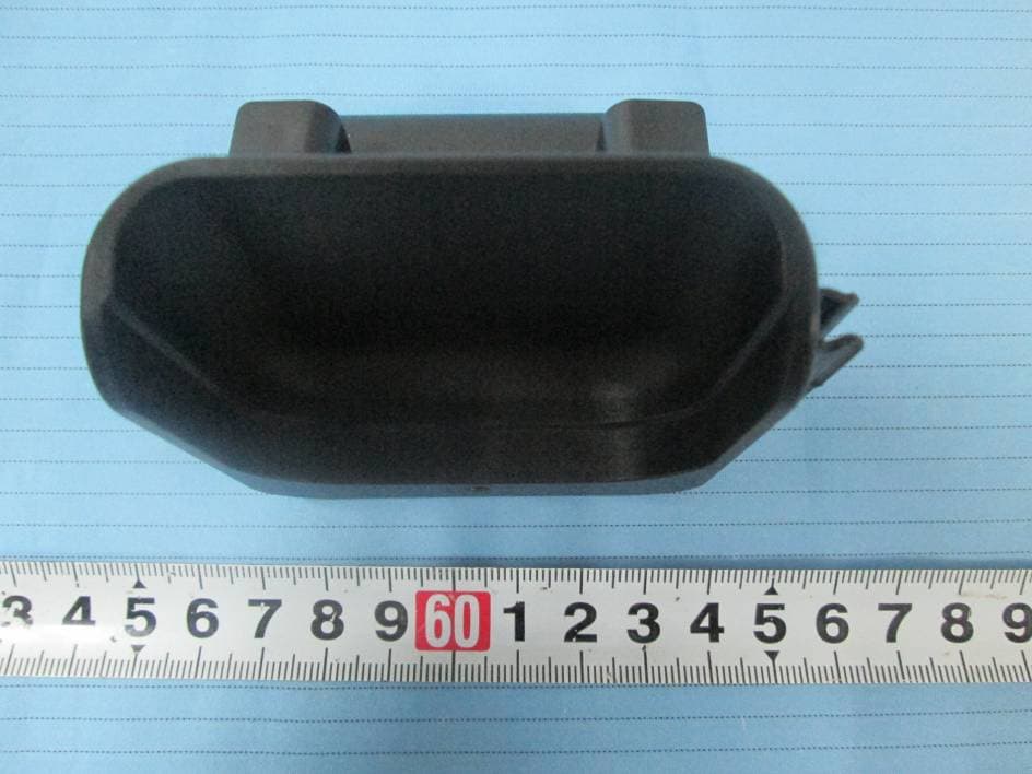
TXRFPT0714
Aug 28, 2014Wireless Grill Thermometer
Equipment Class
DSC - Part 15 Security/Remote Control Transmitter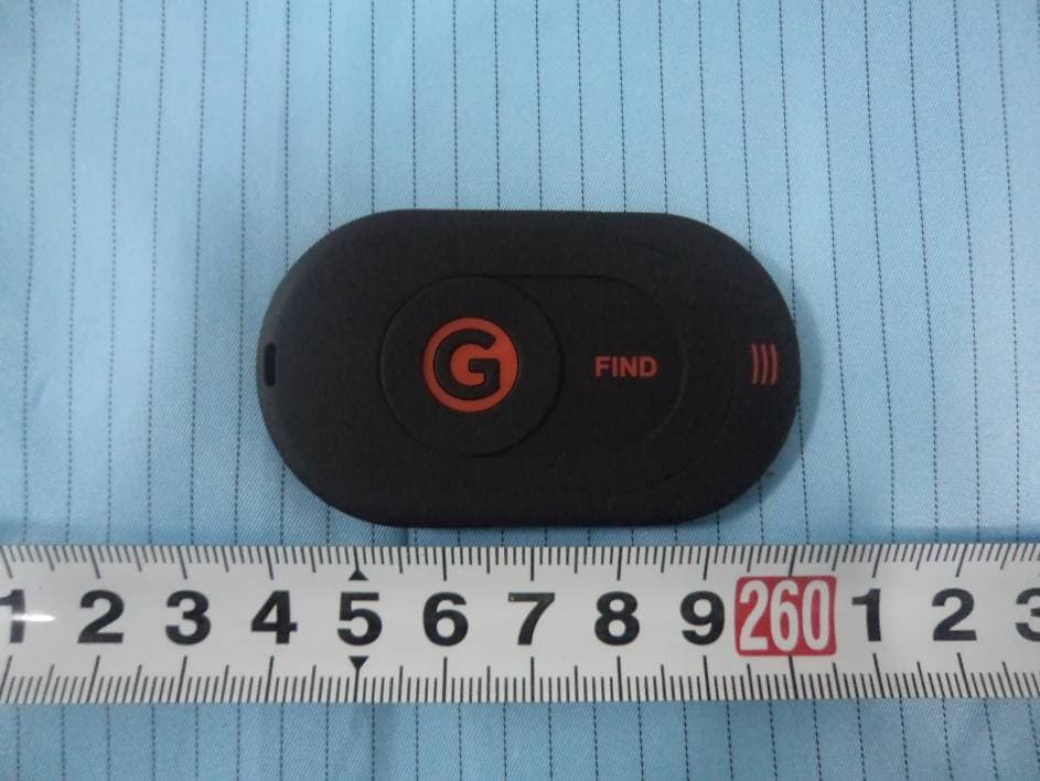
TXRFPT0614
Jul 07, 2014Wireless Key Finder
Equipment Class
DSC - Part 15 Security/Remote Control Transmitter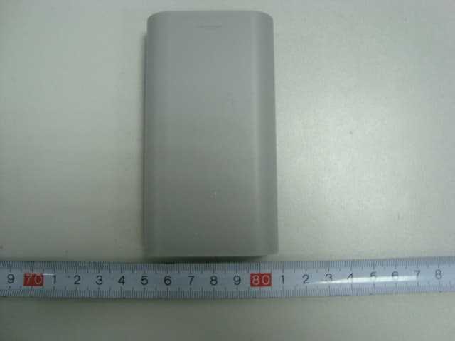
TXRFKF-1006
Aug 21, 2010Remote Key Finder
Equipment Class
DSC - Part 15 Security/Remote Control Transmitter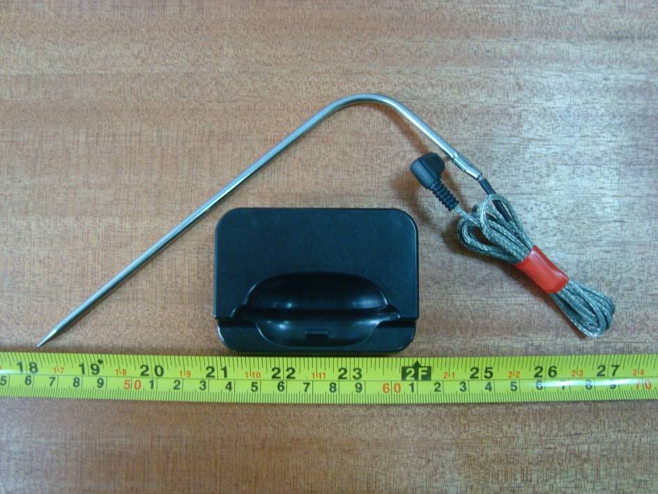
TXRFPT0912
Jan 04, 2010Remote Grill Thermometer
Equipment Class
DSC - Part 15 Security/Remote Control Transmitter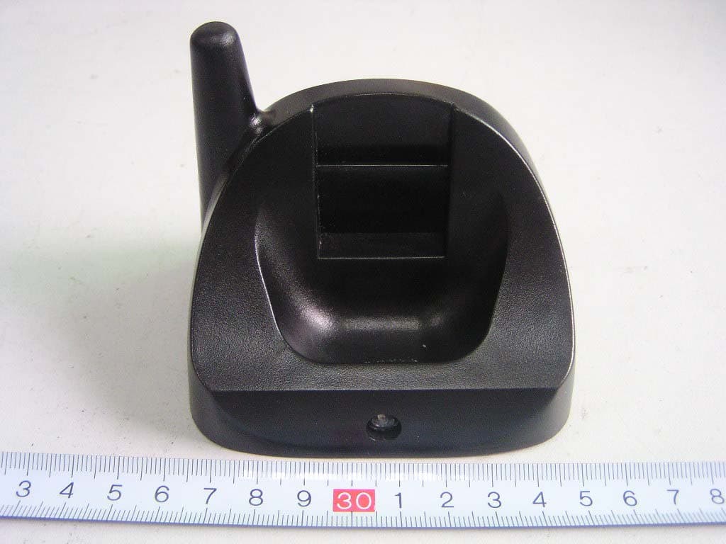
TXRFPT0601
Apr 02, 2006Remote Grill Thermometer
Equipment Class
DSR - Part 15 Remote Control/Security Device Transceiver